1
EXTRA - FLUGZEUGBAU GmbH
SERVICE MANUAL EXTRA 300
Chapter 05
Time Limits/Maintenance Checks
PAGE DATE: 31. January 1995
CHAPTER 05
PAGE
1
EXTRA - FLUGZEUGBAU GmbH
SERVICE MANUAL EXTRA 300
Table of Contents
Chapter
Title
05-00-00
GENERAL
................................................................................................................
05-10-00
05-10-01
05-10-02
05-10-03
TIME LIMIT COMPONENTS
General
Overhaul Schedule
Recommended Replacement Times
05-20-00
05-20-01
05-20-02
05-20-03
05-20-04
05-20-05
SCHEDULED MAINTENANCE CHECKS
General
25 Hour Inspection - Engine
25 Hour Inspection - Aircraft
Maintenance Checks Schedule
Significant Items Inspection
05-50-00
05-50-01
05-50-02
05-50-03
05-50-04
05-50-05
UNSCHEDULED MAINTENANCE CHECKS
Violent Stopping of the Engine (Propeller Strike)
Hard Landing
Engine Fire
Lightning Strike
Flightline Inspections
PAGE DATE: 31. January 1995
.........................................................
............................................................................................................................
...............................................................................................
....................................................
3
4
4
4
5
6
6
6
6
11
24
.......................
............................................................................................................................
......................................................................
....................................................................
..............................................................
...................................................................
..........
.............
........................................................................................................
..............................................................................................................
..................................................................................................
....................................................................................
32
32
32
34
34
35
CHAPTER 05
PAGE
2
EXTRA - FLUGZEUGBAU GmbH
SERVICE MANUAL EXTRA 300
05-00-00
GENERAL
This chapter contains charts for time limits, scheduled
maintenance and unscheduled maintenance, and enables
licensed personnel to carry out correct inspections on the
EXTRA 300. The periodic inspections and checks described and their recommended time intervals are minimum
requirements for maintaining the aircraft in an airworthy
condition. Further information will be given by the information service (Service Bulletins, Service Letters, etc.).
If operation of aircraft requires more frequent servicing, the
check intervals may be shortened. However the check
intervals must not be exceeded without explicit permission
from the regulatory authority. Additional checks as well as
changes must also be agreed by the regulatory authority.
In general this Manual does not give any information about
vendor equipment. Such information can be taken from the
vendor equipment maintenance instructions (refer to Chapter 01). However for practicability reason most of the
applicable vendor equipment inspections are incorporated
in the following checklists. But it has to be noted that the
latest editions of inspections given by the vendors remain
decisive. So, before beginning an inspection, the inspections of vendor equipment presented here must be compared with the originals referenced under the respective
headlines of the checklists, and, in case of doubt (e.g. if
originals have changed before changes could be transferred
to this Manual by the Revision Service), contact EXTRAFLUGZEUGBAU GmbH for advice. The maintenance
instructions referenced in the checklists are also valid if
further inspection of vendor equipment is necessary.
NOTE
For working with checklists refer to Chapter 02-20-03.
DANGER
Do not rotate the propeller nor allow any person to stay
in the propeller operating area when performing an inspection or check with the master switch "ON" and the
battery connected. The engine may be started unintentionally and may cause serious injuries or death.
PAGE DATE: 31.
1. June
January
19961995
CHAPTER 05
PAGE
3
EXTRA - FLUGZEUGBAU GmbH
SERVICE MANUAL EXTRA 300
05-10-00
TIME LIMIT COMPONENTS
05-10-01
General
All components not listed herein should be inspected as
detailed in Chapter 05-20 Maintenance Checks and repaired, overhauled as required. It is recommended that
overhaul or replacement of components should be accomplished not later than the specified period of operation for
that component or in accordance with the manufactures
service data or airworthiness directives.
05-10-02
Overhaul Schedule
Items shown here must be overhauled at the times indicated.
Item
* refer to latest issue of
Manufacturer´s Service Bulletin
Engine
(Textron Lycoming)
Engine accessories
Magneto
(Slick)
Double magnetos
(Bendix)
Propeller
(MT-Propeller)
Governer
(Woodward)
All other components
January
PAGE DATE: 31.
1. June
19961995
Overhaul
*
together with
engine
*
*
*
*
on Condition
CHAPTER 05
PAGE
4
EXTRA - FLUGZEUGBAU GmbH
SERVICE MANUAL EXTRA 300
05-10-03
TIME LIMIT COMPONENTS
Recommended Replacement Times
It is recommended to replace the items shown in the
following schedule at the times indicated. The times may be
modificated by the respective national authorities.
** on the recommendation
of the manufacturer
Item
Battery
(Sonnenschein)
2 years **
Wheels
(Cleveland, Parker)
on Condition
Fuel, oil & brake hoses
(Aeroquip)
after first 7 years,
then 5 years
Brake and Brake Assembly
(Cleveland, Parker)
on Condition
Rudder control cable
on Condition
Fairleads
on Condition
Batteries of the ELT
(Pointer)
Tires
Seat belts
(Hooker)
*** if not stated otherwise
PAGE DATE: 31.
1. June
19971995
January
Replace
Shock mounts
(Lord
Kinematics, Barry Controls)
Bolts and Nuts
2 years **
on Condition
6 years **
on Condition
on Condition ***
CHAPTER 05
PAGE
5
EXTRA - FLUGZEUGBAU GmbH
SERVICE MANUAL EXTRA 300
05-20-00
SCHEDULED MAINTENANCE CHECKS
05-20-01
General
Scheduled maintenance checks or tasks must be carried out
at 25, 50, 100, 200, 300, 400, 500 and 1000 hour intervals.
In addition an annual inspection equal to the 100 hour
inspection has to be performed.
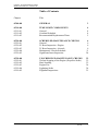
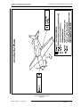
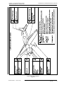
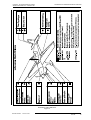
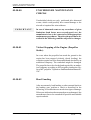
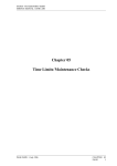
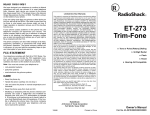
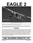
The following pages show a drain hole chart (Figure 1) and
lubrication charts (Figures 2 - 4) which can be used in
connection with the checklists.
05-20-02
25 Hour Inspection - Engine
A 25 hour inspection is necessary for the engine, because
the engine is not equipped with an external oil filter.
Therefore the engine oil has to be changed and the oil screen
cleaned after every 25 hours. Refer to Figure 2 "Lubrication
Chart 25 hours".
05-20-03
25 Hour Inspection - Aircraft
After the first 25 hours, a check equal to the 100-hour
maintenance check has to be performed. Refer to Chapter
05-20-04.
31.June
January
PAGE DATE: 1.
19961995
CHAPTER 05
PAGE
6
SCHEDULED MAINTENANCE CHECKS
EXTRA - FLUGZEUGBAU GmbH
SERVICE MANUAL EXTRA 300
1.
2.
3.
4.
5.
6.
7.
8.
9.
Root Rib Aileron
Root Elevator
Root Horizontal Stabilizer
TrimTab (3 Holes)
Stall Warn Transducer
Lower Root Rudder Fin
Lower Root Rudder Horn
Wheel Fairing
Nose Ribs Aileron (Hinge Gaps)
Drain and Vent Holes
Figure 1
PAGE DATE: 31. January 1995
CHAPTER 05
PAGE
7
EXTRA - FLUGZEUGBAU GmbH
SERVICE MANUAL EXTRA 300
SCHEDULED MAINTENANCE CHECKS
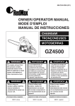
Lubrication Chart 25 hours
Figure 2
31.June
January
PAGE DATE: 1.
19961995
CHAPTER 05
PAGE
8
EXTRA - FLUGZEUGBAU GmbH
SERVICE MANUAL EXTRA 300
SCHEDULED MAINTENANCE CHECKS
Lubrication Chart 50 hours
Figure 3
PAGE DATE: 1.
31.June
January
19961995
CHAPTER 05
PAGE
9
EXTRA - FLUGZEUGBAU GmbH
SERVICE MANUAL EXTRA 300
SCHEDULED MAINTENANCE CHECKS
Lubrication Chart 100 hours
Figure 4
31.June
January
PAGE DATE: 1.
19961995
CHAPTER 05
PAGE
10
EXTRA - FLUGZEUGBAU GmbH
SERVICE MANUAL EXTRA 300
05-20-04
SCHEDULED MAINTENANCE CHECKS
Maintenance Checks Schedule
The maintenance checks described in this Chapter include
all the scheduled checks which must be performed. Use the
following schedule and the lubrication charts (Figures 2-4).
Date:
rs
s
d our hou
e
h 0
Serial No.:
ifi
ec 50 10
p
h
h
s
c
as ea eac
Inspector:
Inspections
Mechanic:
Operational Checks
O O
1 Start engine (in accordance with the Pilot`s Operating Handbook)
O O
3 Check oil pressure and temperature.
O O
O O
O O
O O
O O
O O
O O
2 Check the fuel quantity indication.
4 Check generator output.
5 Check magneto RPM-drop at 1800 RPM. (Allowed drop is
175 RPM and no greater diff. between L + R from 50 RPM)
6 Check ignition OFF function at 1000 RPM for a short
moment.
7 Check response of the engine by power setting changes.
8 Check the Propeller response at 1800 RPM when changing
pitch.
9 Check idle speed is between 650 and 750 RPM.
O O 10 Check the fuel flow and manifold pressure indicator.
O O 11 Check the EGT and CHT indicator.
O O 12 Check mixer function per CHT/EGT indication.
O O 13 Check idle mixture.
O O 14 Check the function of the fuel selector valve.
O O 15 Check the radio and the other electronic equipment.
O O 16 Shut down engine using mixture lever. Check the alternator
warning light or ammeter.
PAGE DATE:
January
DATE: 31.
1. June
19961995
CHAPTER 05
PAGE
11
EXTRA - FLUGZEUGBAU GmbH
SERVICE MANUAL EXTRA 300
SCHEDULED MAINTENANCE CHECKS
Maintenance Checks Schedule
Date:
rs
rs
d hou hou
e
0
Serial No.:
ifi 0
ec h 5 10
p
c
h
s
a
as e eac
Inspector:
Inspections
Mechanic:
O O 17 Check the optional electronic g-meter for the maximum gloading. If extreme value exceeds ±10 G, contact EXTRAFlugzeugbau GmbH. Correct date and time of the g-meter
(refer to DSA-12 Manual).
O O 18 Ignition OFF, main switch OFF, remove ignition key.
O O 19 Check if ignition key is removable in OFF-position only, and
if key functions in accordance with the requirements of the
Teledyne Continental Service Bulletin No. 636.
Propeller
(refer to latest edition of MT-Propeller Operation and Installation Manual E-124 and Service Bulletins)
DANGER
O
O O
O O
O
O
O O
O O
O
O O
Ground magneto primary circuit before
working on propeller
1 Remove spinner and check for cracks.
2 Check blade shake, max. 3 mm or 1/8 inch.
3 Check blade angle play, max. 2°.
4 Inspect outside condition of the hub and parts for cracks,
corrosion, deterioration.
5 Inspect check nut for high pitch stop for tightness.
6 Check all safety means to be intact.
7 Check flange bolts or stopnuts for tightness.
8 Check front and rear spinnerplate for cracks and fixing.
9 Inspect bladeroot and hub for oil- and grease leaks.
O 10 Check position and condition of counterweights.
O1
O O 11 Check blades for cracks in the fibreglass-cover and blade
erosion sheet. No cracks allowed. Refer to MT-Propeller SB
No. 8
12 Overhaul propeller or perform a tear-down inspection.
1 refer to MT-Propeller Service Bulletin No. 1
PAGE DATE:
DATE: 1.
31.June
January
PAGE
19961995
CHAPTER 05
PAGE
12
EXTRA - FLUGZEUGBAU GmbH
SERVICE MANUAL EXTRA 300
SCHEDULED MAINTENANCE CHECKS
Maintenance Checks Schedule
rs
Date:
s
d our hou
e
h 0
Serial No.:
ifi
ec h 50 h 10
p
s
c
c
as ea ea
Inspector:
Inspections
Mechanic:
Engine compartment
(Refer to latest edition of Textron Lycoming Operator´s
Manual and SB's, of Christen Product Manual 801 Series and
SB's, of Slick Magneto Maintenance and Overhaul Manual
and SB's and of TCM/Bendix Service Support Manual,
included in Form X40000 Master Service Manual and SB's)
DANGER
Ground magneto primary circuit before
working on engine
O O
1 Remove engine cowling.
O O
3 After this inspection clean cowling.
O O
O O
O1 O O
O1 O O
O1 O O
O1 O O
2 Inspect cowling and air inlet screen for damage, cracks,
distortion, overheated areas and loose or missing blindnuts
and secure attachment of oil level access plate.
4 Check fire protection according to EXTRA Service Bulletin
300-6-94. If necessary repaint the fire protection paint
("WIEDOFLUGAT" Brandschutzfarbe N 56582 / T508).
5 Drain oil sump in accordance with Chapter 12-10-04 Engine Oil Replenishing
6 Clean and inspect oil screen filter
7 Clean suction oil strainer at oil change (check strainer for
foreign particles).
8 Clean pressure oil strainer (check for foreign particles)
O2 O O 8a Change full flow (cartridge type, AEIO-540-L1B5/D engine) oil filter element (check element for foreign particles).
O
9 Inspect oil temperature sensor unit for leaks and security.
O O 10 Inspect flexible oil lines, oil return lines and fittings for leaks,
security, chafing, dents, and cracks (ref: FAA AC 43.13-1A).
Replace flexible oil lines at engine TBO per Lyc. SB 240.
Check fire protection according to EXTRA SB 300-6-94.
O3
O 11 Clean and inspect oil radiators and attachment.
12 Remove and flush oil radiators.
1 at 10 and 25 hours and then each 25 hours
2 at 10 and 25 hours
3 each 500 hours
15. January
December
1999
PAGE DATE: 31.
1995
CHAPTER 05
PAGE
13
EXTRA - FLUGZEUGBAU GmbH
SERVICE MANUAL EXTRA 300
Date:
rs
s
d our hou
e
i
f 0h 0
Serial No.:
0
ci
pe h 5 h 1
s
c
as ea eac
O O
O1
SCHEDULED MAINTENANCE CHECKS
Maintenance Checks Schedule
Inspector:
Inspections
Mechanic:
Inspect Christen Inverted Oil System for general condition,
leaks, secure mounting and tight connections.
13 Clean and flush the Inverted Oil System with a suitable
petroleum solvent, such as varsol according to Lycoming
Operators Manual.
O2 O O 14 Service engine with recommended lubricating oil in accordance with Chapter 12-10-04.
O O 15 Inspect condition of spark plugs (Clean and adjust gap as
required, adjust per Lycoming Service Instruction 1042). If
fouling of spark plugs has been apparent, rotate buttom plugs
to upper plugs and vice versa.
O O 16 Inspect spark plug cable leads and ceramics for corrosion and
deposits.
O O 17 Perform a hot engine differential compression check in
accordance with FAA AC 43.13-1A.
O 18 Inspect cylinders for cracked or broken fins.
O O 19 Check cylinders for evidence of excessive heat which is
indicated by discoloration.
O 20 Check fuel injector nozzles for loseness. Tighten to 60 inch
pounds torque. Check fuel lines for fuel stains which are
indicative for fuel leaks.
O3
O O 21 Inspect rocker box covers for evidence of oil leaks. If found,
replace gasket; torque cover screws 50 Inch-pounds.
22 Remove rocker box covers and check for freedom of valve
rockers when valves are closed. Look for evidence of abnormal wear or broken parts in the area of valve tips, valve
keeper, springs and spring seats.
O 23 Inspect ignition harness for general condition, free from
fraying or chafing and insulators for high tension leakage and
continuity.
1 each 300 hours
2 each 25 hours
3 each 400 hours
PAGE DATE: 1.
31.June
January
19961995
CHAPTER 05
PAGE
14
EXTRA - FLUGZEUGBAU GmbH
SERVICE MANUAL EXTRA 300
Date:
rs
s
d our hou
e
i
f 0h 0
Serial No.:
0
ci
pe h 5 h 1
s
c
as ea eac
SCHEDULED MAINTENANCE CHECKS
Maintenance Checks Schedule
Inspector:
Inspections
Mechanic:
TCM/Bendix magnetos
O 24 Check magneto-to-engine timing.
O 25 Remove all ignition harness spark plug terminals from spark
plugs, clean and inspect following the respective sections of
the applicable Support Manual.
O1
O1
O2
O 26 Inspect magnetos with riveted impulse coupling for wear as
specified in the latest revision of TCM/Bendix SB 599D.
27 Inspect magnetos equipped with snap-ring impulse coupling
for wear as outlined in the PERIODIC MAINTENANCE
Section of the applicable Support Manual, Paragraph 6.2.2.
28 Inspect magnetos as outlined in the PERIODIC MAINTENANCE Section of the applicable Support Manual, Paragraph 6.2.3. Clean and inspect all ignition harness outlet
plates, covers or cap assemblies and grommets following the
respective sections of the Manual mentioned above.
29 Overhaul or replace magnetos acc. to TCM/Bendix SB 643.
Slick magnetos
O 24 Adjust magneto to engine timing, refer to Slick Magneto
Maintenance and Overhaul Manual
O1
O1
O3
O1
O4
1
2
3
4
O 25 Inspect wiring connections, vent holes and P-lead
attachment, refer to Slick Magneto Maintenance and Overhaul Manual.
26 Clean magnetos.
27 Inspect ball bearing assembly, impulse coupling, coil, contact points, condenser and carbon brush.
28 Replace ball bearings.
29 Lubricate magnetos.
30 Overhaul or replace magnetos.
each 500 hours
at engine overhaul and at the expiration of 4 years
each 1000 hours
together with engine
January
PAGE DATE: 31.
1. June
19961995
CHAPTER 05
PAGE
15
EXTRA - FLUGZEUGBAU GmbH
SERVICE MANUAL EXTRA 300
Date:
rs
s
d our hou
e
i
f 0h 0
Serial No.:
0
ci
pe h 5 h 1
s
c
as ea eac
SCHEDULED MAINTENANCE CHECKS
Maintenance Checks Schedule
Inspector:
Inspections
Mechanic:
O 31 Check fuel injector for general condition, clean fuel inlet
screen.
O O 32 Inspect intake seals and O-rings for leaks and clamps for
tightness.
O O 33 Inspect flexible fuel lines, fuel injection lines and fittings for
leaks, security, chafing, dents, and cracks (refer to Lycoming
SB 342 each 100h; replace or overhaul as required or at
engine overhaul). Check fire protection according to EXTRA
SB 300-6-94.
O O 34 Check fuel system for leaks.
O1 O O 35 Remove, clean and inspect gascolator screen and fuel filter
bowl.
O O 36 Inspect throttle, mixture, and propeller governor controls for
security, travel, and operating conditions.
O O 37 Inspect exhaust stacks, connections and gaskets (replace
gaskets as required).
O O 38 Inspect exhaust slipjoints for general condition.
O O 39 Inspect exhaust system attachment.
O 40 Inspect crankcase for cracks, leaks, and security of seam
bolts.
O O 41 Check engine mounted accessories such as pumps, temperature and pressure sensing units for leaks, secure mounting
and tight connections.
O O 42 Inspect engine mount for cracks and loose mountings.
O O 43 Inspect engine baffles free from cracks and fraying.
O 44 Inspect all wiring connected to the engine or accessories
O O 45 Inspect engine shock mounts for deterioration (replace as
required).
O 46 Inspect firewall seals (see EXTRA SB 300-6-94).
O 47 Inspect alternator, cable connections and accessories.
1 clean at least every 90 days
31.June
January
PAGE DATE: 1.
19961995
CHAPTER 05
PAGE
16
EXTRA - FLUGZEUGBAU GmbH
SERVICE MANUAL EXTRA 300
rs
Date:
rs ou
u
d
h
o
e
i
f 0 h 00
Serial No.:
ci
1
pe h 5 ch
s
c
as ea ea
Inspector:
Inspections
Mechanic:
O 48 Inspect condition and tension of alternator drive belt
O 49 Inspect security of alternator mounting
O 50 Inspect starter and starter drive
O O 51 Check brake fluid level (fill as required).
O O 52 Clean engine if necessary.
O1
O2
O O 53 Lubricate all controls per lubrication chart.
54 Overhaul or replace propeller governor as required.
55 Complete overhaul of engine or replace with factory rebuilt
O O 56 Reinstall engine cowling.
O O
O
O O
O O
O O
O
O O
O O
Fuselage
1 Remove tail fairing, tail side skins, tank covering sheet, turtle
deck and landing gear cuffs per Chapter 51.
2 Remove bottom covering window and sheets including exhaust area covering sheet per Chapter 51.
3 Inspect tank covering sheet, turtle deck, bottom covering
window and sheets including exhaust area covering sheet,
tail fairing, tail side skins and landing gear cuffs for general
condition, dents, cracks and loose screws and rivets.
4 Check installed parts for general condition and security of
attachment.
5 Inspect fuselage for foreign matters.
6 Inspect steel tube construction for general condition, corrosion and cracks, above all in areas of load stress (e.g. wing,
stabilizer, engine and seat attachments).
7 Visually inspect steel tube construction in the area of horizontal stabilizer attach brackets for cracks. In case of doubt
remove horizontal stabilizer and use a dye check penetrant.
In case of cracks are found contact EXTRA-FLUGZEUGBAU
GmbH for repair advise.
8 Inspect fabric cover for general condition.
1 refer to Woodward Service Bulletin No. 33580
2 refer to Lycoming Service Instruction No. 1009
31.June
January
PAGE DATE: 1.
19961995
CHAPTER 05
PAGE
17
EXTRA - FLUGZEUGBAU GmbH
SERVICE MANUAL EXTRA 300
Date:
rs
s
d our hou
e
i
f 0h 0
Serial No.:
0
ci
pe h 5 h 1
s
c
as ea eac
O
SCHEDULED MAINTENANCE CHECKS
Maintenance Checks Schedule
Inspector:
Inspections
Mechanic:
9 Inspect wooden longerons for damage.
O 10 Clean and lubricate canopy hinge and latching mechanism.
O O 11 Inspect seats and seat belts for security, attachment, proper
operation, and condition. Control the time limit of the seat
belts. Refer to Chapter 05-10-02 "Overhaul Schedule".
O 12 Inspect breather line for obstructions and security.
O 13 Inspect main and auxiliary wing spar connector for general
condition.
O O
O O
O O
O O
O O
O O
O O
O O
Fuel system
1 Inspect the fuel lines for leaks, security, chafing, dents and
cracks. Replace fuel lines as required.
2 Inspect fuel selector valve for operation and proper pointer
indication
3 Drain fuel system
4 Check acro- and center tank attachment
5 Check acro-, center- and both wingtanks for leaks
6 Check boost pump
7 Check fuel filler caps for security and proper operation
8 Check proper seat and condition of sealing lip (from S.No 59)
Flight controls
O O
1 Remove wing access panels.
O O
3 Inspect elevator trim system for proper operation and rigging.
O O
O O
O O
O1 O O
2 Inspect control surfaces for security of attachment, free
movement, dents, delaminations and cracks.
4 Inspect hinges for condition, cracks and security; hinge bolts,
hinge bearings, selflocking nuts.
5 Check free play in control system: torque tube, control
surfaces, control sticks, rod end bearing, deflector limiter.
6 Lubricate rear torque tube bearing.
1 each 25 hours
31.June
January
PAGE DATE: 1.
19961995
CHAPTER 05
PAGE
18
EXTRA - FLUGZEUGBAU GmbH
SERVICE MANUAL EXTRA 300
Date:
rs
s
d our hou
e
i
f 0h 0
Serial No.:
0
ci
pe h 5 h 1
s
c
as ea eac
O O
O
O O
SCHEDULED MAINTENANCE CHECKS
Maintenance Checks Schedule
Inspector:
Inspections
Mechanic:
7 Lubricate aileron rodend bearings, trim flap hinges and trim
lever bolt.
8 Lubricate adjustment tube of electrical pedal adjustment.
9 Check rudder cable system including sleeves, fairleads,
pulleys and cable retracting springs per FAA-AC 43.13-1A.
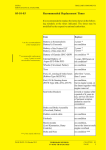
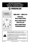
O 10 Check for minimum 3.5 mm (1/8") clearance of rudder pedal
versus safety stop when fully deflected for rudder cables
having 50 h flight time minimum. On newly installed rudder
cables the minimum spacing is 6 mm (1/4"). Refer to Figure 5.
This check is to be performed with zero loading on the rudder
pedals.
O 11 Rough check of safety stop clearance. With a force of approx.
90 kg (200 lbs) acting on the fully deflected rudder pedal the
safety stop shall not be reached. If the stop is reached the
control system indicates a too high flexibility which needs to
be traced. In this case contact EXTRA for advice.
O O 12 Inspect all flight control ventilation holes for obstruction.
O 13 Inspect elevator balance weight for looseness and condition.
O 14 Inspect push rods.
Landing gear
O O
1 Check landing gear for general condition.
O O
3 Inspect landing gear spring mounting clamps and bolts for
security.
O O
O
O
2 Check landing gear spring for dents and cracks.
4 Lubricate landing gear center bolt and landing gear bearings.
5 Check wheel rake (10° ± 0.5°) and toe-in (1.5° ± 0.5°) per
Chapter 32.
Fairings:
O O
1 Disassemble fairings.
O O
3 Check fairing ventilation hole for obstruction.
O O
2 Check fairings for dents and cracks.
31.June
January
PAGE DATE: 1.
19961995
CHAPTER 05
PAGE
19
EXTRA - FLUGZEUGBAU GmbH
SERVICE MANUAL EXTRA 300
Date:
rs
s
d our hou
e
i
f 0h 0
Serial No.:
0
ci
pe h 5 h 1
s
c
as ea eac
Wheels
O O
O O
O O
O
O
O
O
SCHEDULED MAINTENANCE CHECKS
Maintenance Checks Schedule
Inspector:
Inspections
Mechanic:
(refer to on-aircraft inspections presented in the latest edition
of Cleveland Wheels & Brakes Maintenance Manual and
Service Bulletins for wheel, tire and break inspections)
1 Visually inspect the wheels for corrosion, cracks, or other
visible damage.
2 Check wheel nuts to be sure they are properly installed and
have not worked loose. Bolt threads should be flush to 1-1/2
threads extending beyond the nut. Nuts should be on the side
of wheel opposite the brake disc (outboard side of wheel).
3 Inspect the brake disc for rust, excessive grooves, large
cracks, coning or other visible damage. Check if disc thickness is more than 0.325in/8.255mm. Coning of disc in excess
of 0.015 in /0.381 mm is cause for replacement (see Fig. 6).
4 Remove wheels and wheel bearings. Inspect wheel bearing
grease for contamination and solidification.
5 Inspect snap rings and grease seals for distortion or wear.
Replace grease seal felts if they are hard or contaminated.
Lightly saturate grease seals should be replaced if cracked,
dried out, or distorted.
6 Inspect wheel bearings for excessive wear or damage. Replace on condition.
7 Repack bearings with AEROSHELL 22C (per MIL-G-81322),
or equivalent. Reinstall wheels and safety.
O O
8 Check wheel bearing clearance and wheels for free rotation.
O O
1 Visually inspect tires for cuts, flat spots, and tread or sidewall
damage. If changing of tires is necessary follow the instructions, including off-aircraft inspection of wheels, presented
in the Cleveland Wheels & Brakes Component Maintenance
Manual.
O O
Tires
2 Check inflation pressure (3.4 bar /49.3 psi). Proper inflation
will provide maximum tire and wheel life.
January
PAGE DATE: 31.
1. June
19961995
CHAPTER 05
PAGE
20
EXTRA - FLUGZEUGBAU GmbH
SERVICE MANUAL EXTRA 300
Date:
rs
s
d our hou
e
i
f 0h 0
Serial No.:
0
ci
pe h 5 h 1
s
c
as ea eac
O O
O O
O
O
O O
O O
O O
O O
O O
Brake system
SCHEDULED MAINTENANCE CHECKS
Maintenance Checks Schedule
Inspector:
Inspections
Mechanic:
1 Inspect brake assemblies for general condition.
2 Inspect master cylinders for leaks.
3 Inspect brake system plumbing for leaks and hoses for bulges
and deterioration.
4 Lubricate brake guide pins using Silicone-base lubricant.
5 Visually inspect the brakes for corrosion, cracks, or other
visible damage. Check inlet fitting bosses and anchor bolt
lugs for cracks. Check inlet flares on aircraft side of rigid
hydraulic tubing for fatigue cracks.
6 Check back plate attachment bolts to insure they are properly
torqued and have not worked loose. Gaps between the back
plate and cylinder would be evidence of this.
7 Check fit of brake cylinder anchor bolts in torque plate
bushings for sloppiness. This can be accomplished by grasping the cylinder and moving it; slight movement is normal.
Excessive movement is cause for removal and detailed
inspection.
8 Linings should be visually checked for extreme chipping on
the edges. Lining worn to a minimum thickness of 0.100 inch
(2.54 mm) must be replaced.
9 Visually check torque plate for corrosion, cracks, loose
anchor bolt bushings, or other visible damage. Anchor bolt
bushings must be flat against torque plate surface.
O O 10 Check for any brake fluid leaks.
O O 11 Check brake fluid level.
Tail-wheel landing gear
O O
1 Check tail-wheel landing gear for general condition.
O O
3 Check tail-wheel rubber tire condition.
O O
2 Check tail-wheel landing gear spring for dents, cracks, and
delaminations.
31.June
January
PAGE DATE: 1.
19961995
CHAPTER 05
PAGE
21
EXTRA - FLUGZEUGBAU GmbH
SERVICE MANUAL EXTRA 300
Date:
rs
s
d our hou
e
i
f 0h 0
Serial No.:
0
ci
pe h 5 h 1
s
c
as ea eac
O O
O O
O O
O
O O
O O
O O
O O
O O
O O
O O
O
O
O
O
O
O O
SCHEDULED MAINTENANCE CHECKS
Maintenance Checks Schedule
Inspector:
Inspections
Mechanic:
4 Inspect tail-wheel spring and swivel arm mounting bolts for
security.
a) Standard: Full-swivel tailwheel
1 Check swivel arm for dents and cracks.
2 Check tail wheel for free rotation and swivel feature.
3 Check swivel arm and wheel bearing clearance, service.
b) Optional: Steerable tailwheel
1 Check for general condition and function. Pay attention to
the free movement of the rudder.
2 Check the connector springs for light precompression.
3 Check the wheelfork for free rotation and steering function,
damage, dents, cracks and corrosion.
4 Inspect wheelfork for damage, dents, cracks and corrosion.
5 Inspect the axle bolt and nut for fretting, wear, damage, and
stretch.
6 Lubricate tail wheel steering.
Wing
1 Check wing for dents, cracks, and delaminations.
2 Inspect wing spar main bolts for looseness and security.
3 Check the safety wire and the safety screw of the wing main
spar bolt.
4 Inspect wing spar main sleeves for looseness and bearing
load.
5 Inspect wing auxiliary spar attachment.
6 Inspect wing ventilation holes for obstruction.
7 Check inside wing structure in the area of access panels.
January
PAGE DATE: 31.
1. June
19961995
CHAPTER 05
PAGE
22
EXTRA - FLUGZEUGBAU GmbH
SERVICE MANUAL EXTRA 300
Date:
rs
s
d our hou
e
i
f 0h 0
Serial No.:
0
ci
pe h 5 h 1
s
c
as ea eac
O O
O O
O O
O
Inspector:
Inspections
Mechanic:
1 Check stabilizer for dents, cracks; stone nicks and
delaminations.
2 Inspect stabilizer spars main bolts for looseness and security.
3 Inspect stabilizer auxiliary spars attachment.
4 Inspect stabilizer ventilation holes for obstruction.
Instruments
O
1 Inspect panel mounting for security and safety.
O
3 Check automatic circuit breaker mounting and wiring for
condition and safety.
O
O
O O
O O
O1
Stabilizer
SCHEDULED MAINTENANCE CHECKS
Maintenance Checks Schedule
O
O O
O O
O
O
O O
2 Check operation, mounting, and wiring of switches for
condition and safety.
4 Inspect stall warner system for condition and security of
installation, perform operational check.
5 Check wingtip position /strobe lights for security and operation.
6 Inspect compass and compass deviation card for proper
indication and compensation.
7 Magnetic compass compensation.
8 Check pitot /static air pressure lines for condition and leaks,
perform operational check.
Electrical system
1 Check engine bonding
2 Check tank bonding (wing- and center tank)
3 Check system wiring free from fraying or cracks
4 Inspect battery and attachment
5 Charge battery
1 Annual, each twelve calendar month
PAGE DATE: 31.
1. June
January
19961995
CHAPTER 05
PAGE
23
EXTRA - FLUGZEUGBAU GmbH
SERVICE MANUAL EXTRA 300
05-20-05
SCHEDULED MAINTENANCE CHECKS
Significant Items Inspection
Every 1000 flight hours the "Significant Items Inspection"
must be performed in addition to the 100-hour inspection.
Date:
s
ur
ho Serial No.:
00
10
Wing
O
O
Inspector:
Inspections EXTRA 300
Mechanic:
Leading edge
1 Detailed visual inspection on the surface for erosion, scratches, stone
nicks and impact damages.
2 Detailed visual inspection on the bonding top/bottom for dents,
cracks and delaminations.
O
3 Inspect grounding rivets visually.
O
4 Check bonding skin/spar for delaminations by coin tapping (Refer to
Chapter 20-10-05).
O
Main spar section
5 Detailed visual inspection on the sparweb for dents, cracks and
delaminations by visual inspection through wing access holes using
a boroscope.
Auxiliary spar section
O
6 Check bonding skin/spar for delamination by coin tapping .
O
8 Inspect attachment fitting for damage, corrosion and link bolts
security.
O
O
7 Detailed visual inspection on the aux. spar web for dents, cracks and
delaminations. Pay particular attention to the cutout for aileron
cantilever.
Spar carry-through
9 Remove spar cap paint by a solvent. Perform visual inspection for
dents and cracks. Check for delaminations by coin tapping. Restore
finish in accordance with Chapter 51-70-05.
O 10 Remove spar web paint by a solvent. Perform visual inspection for
dents and cracks. Check for delaminations by coin tapping. Restore
finish in accordance with Chapter 51-70-05.
PAGE DATE: 31.
1995
15. January
December
1999
CHAPTER 05
PAGE
24
EXTRA - FLUGZEUGBAU GmbH
SERVICE MANUAL EXTRA 300
Date:
s
ur
ho Serial No.:
00
10
SCHEDULED MAINTENANCE CHECKS
Significant Items Inspection
Inspector:
Inspections
Mechanic:
O 11 Check main bolt sleeves for secure bonding to the spar.
Wing trailing edge
O 12 Check bonding top/bottom for cracks and delaminations by coin
tapping (Refer to Chapter 20-10-05).
Root and Tip
O 13 Check root rib for cracks, delaminations and secure bonding to skin
and spars by coin tapping (Refer to Chapter 20-10-05).
O 14 Inspect tip rib visually for general condition.
O 15 Check metall fittings (power supply support) for secure bonding to
the carbon laminate
Aileron
O
1 Check root and tip rib bonding to the skin laminate by coin tapping.
O
3 Checkbonding top/bottom for cracks and delaminations by coin
tapping (Refer to Chapter 20-10-05).
O
O
O
2 Check bonding skin/spar for delaminations by coin tapping.
4 Check hinge points (mounting brackets) and actuator for damages and
cracks. Ensure proper attachment.
5 Inspect spades visually for general condition. Check spade support
for corrosion, cracks and deformations. Ensure proper attachment to
aileron.
O
6 Inspect ventilation holes for obstruction.
O
1 Check painting visually for general condition (blisters etc.).
O
O
O
O
Surface general
2 Check laminate for erosion, scratches and nicks.
Control system
1 Inspect bell cranks for damage, corrosion, security of mounting and
link bolts through wing access holes.
2 Inspect control rods for corrosion.
3 Check Rod end bearing for free movement and cleanliness.
PAGE DATE: 31. January 1995
CHAPTER 05
PAGE
25
EXTRA - FLUGZEUGBAU GmbH
SERVICE MANUAL EXTRA 300
Date:
s
ur
ho Serial No.:
00
10
Vertical Stabilizer
O
SCHEDULED MAINTENANCE CHECKS
Significant Items Inspection
Inspector:
Inspections
Mechanic:
Leading edge
1 Check surface for erosion, scratches, stone nicks and impact damages.
O
2 Check bonding left/right for dents, cracks and delamination.
O
3 Check bonding skin/spar for delamination by coin tapping (Refer to
Chapter 20-10-05).
O
Front spar section
4 Detailed visual sheet metal attachment fitting for damage, corrosion
and link bolts security.
Rear spar section
O
5 Check bonding skin/spar for delamination by coin tapping .
O
7 Check steel sleeve for secure bonding to the spar.
O
O
O
6 Detailed visual rear spar web for dents, cracks and delamination. Pay
particular attention to the cut out for rudder cantilever.
8 Replace attachment bolts and stop nuts. Check for proper torque in
accordance with Chapter 20-10-02.
Root and Tip
9 Check root rib for cracks, delamination and secure bonding to skin
and spars by coin tapping.
O 10 Inspect tip rib visually for general condition.
Rudder
O
1 Check tip rib bonding to the skin laminate by coin tapping.
O
3 Check bonding trailing edge for cracks and delaminations by coin
tapping.
O
O
O
O
2 Check bonding skin/spar for delamination by coin tapping.
4 Detailed visual of mounting brackets for damages and cracks. Ensure
proper attachment. Replace bolts and stop nuts for new ones in any
case. Check for proper torque in accordance with Chapter 20-10-02.
5 Check actuator lever for damage, cracks and proper attachment.
6 Inspect ventilation holes visually for obstruction. Refer to Chapter
05-20-01, Figure 2 "Drain and Vent Holes".
PAGE DATE: 31. January 1995
CHAPTER 05
PAGE
26
EXTRA - FLUGZEUGBAU GmbH
SERVICE MANUAL EXTRA 300
O
O
O
O
Date:
s
ur
ho Serial No.:
00
10
SCHEDULED MAINTENANCE CHECKS
Significant Items Inspection
Inspector:
Inspections
Mechanic:
7 Check painting visually for general condition (blisters etc.).
8 Check laminate for erosion, scratches and stone nicks.
Horizontal Stabilizer
Leading edge
1 Check surface for erosion, scratches, stone nicks and impact damage.
2 Check bonding top/bottom for dents, cracks and delamination.
Front spar section
O
3 Check bonding skin/spar for delamination by coin tapping.
O
4 Check bonding skin/spar for delamination by coin tapping.
O
5 Remove spar cap paint by a solvent. Perform visual inspection for
dents and cracks. Check for delamination by coin tapping. Restore
finish in accordance with Chapter 51-70-05.
O
O
Rear spar section
Spar carry-through
6 Remove Spar web paint by a solvent. Perform visual inspection for
dents and cracks. Check for delaminations by coin tapping. Restore
finish in accordance with Chapter 51-70-05.
7 Replace attachment bolts and stop nuts. Check for proper torque in
accordance with Chapter 20-10-02.
O
8 Check steel sleeves for secure bonding to the spar.
O
9 Check root rib for cracks, delamination and secure bonding to skin
and spars by coin tapping.
Root and Tip
O 10 Inspect tip rib visually for general condition.
Elevator
O
1 Check tip rib bonding to the skin laminate by coin tapping.
O
3 Check bonding trailing edge for cracks and delamination by coin
tapping.
O
O
2 Check bonding skin/spar for delaminations by coin tapping.
4 Detailed visual inspection of mounting brackets for damage, cracks
and proper attachment. Replace bolts and stop nuts. Check for proper
torque in accordance with Chapter 20-10-02.
15. January
December
1999
PAGE DATE: 31.
1995
CHAPTER 05
PAGE
27
EXTRA - FLUGZEUGBAU GmbH
SERVICE MANUAL EXTRA 300
O
O
O
O
O
Date:
s
ur
ho Serial No.:
00
10
SCHEDULED MAINTENANCE CHECKS
Significant Items Inspection
Inspector:
Inspections
Mechanic:
5 Check center section for delamination by coin tapping.
6 Detailed visual of actuator lever for damage, cracks and proper
attachment.
7 Detailed visual of mass balance attachment and mounting boom for
deformation, corrosion and cracks.
8 Detailed visual of trim tab hinges, actuator lever for damage, cracks,
excessive wear and proper bonding to the laminate. Detailed visual
for delamination.
9 Inspect ventilation holes for obstruction.
Surface general
O 10 Check painting for general condition (blisters etc.).
O 11 Check laminate for erosion, scratches, stone nicks and impact damages.
O
O
O
O
Fuselage
1 Inspect tubular steel frame visually for corrosion, scratches and
damages.
2 Check wing main spar attachment for damage and corrosion. Inspect
for dents and cracks.
3 Detailed visual of the sheet metal of the wing auxiliary spar attachment for damage, corrosion. Inspect the sheet metal supports using a
fluorescent dye penetrant to insure no cracks are evident.
4 Detailed visual of cockpit frame visually for dents, cracks and
delaminations.
O
5 Inspect main fuselage cover visually for dents, cracks and delamination.
O
1 Detailed visual of torque tube for damages, cracks, free-play and stop
adjustments.
O
O
O
Flight controls
2 Detailed visual of bell cranks for damage, cracks, corrosion, security
of mounting and link bolts.
3 Inspect control rods for loose or popped rivets and general condition.
4 Inspect sticks (rear & front) for full travel, proper rigging, free-play,
security of mounting and direction of control surface movement with
relation to stick movement.
PAGE DATE: 31. January 1995
CHAPTER 05
PAGE
28
EXTRA - FLUGZEUGBAU GmbH
SERVICE MANUAL EXTRA 300
O
O
O
O
O
O
O
O
Date:
s
ur
ho Serial No.:
00
10
SCHEDULED MAINTENANCE CHECKS
Significant Items Inspection
Inspector:
Inspections
Mechanic:
5 Check rod end bearings for free movement and cleanliness.
6 Detailed visual of trim actuator lever for damages and cracks. Ensure
proper attachment and condition of friction.
Main landing gear
1 Inspect landing gear spring visually for dents, cracks and delaminations,
especally at the axle attachment and the center bushing for wear and
looseness.
2 Check mounting clamp for damage and corrosion. Inspect for dents
and cracks.
3 Inspect mounting clamp bolts and nuts for fretting, wear, damage,
stretch and proper torque (refer to Chapter 20-10-03).
4 Check brakes discs for warping and wear. Inspect wheel brake
cylinder mounting brucket for wear.
5 Inspect brake lines for leakage, dents, cracks, chaffing, kinks and
security of anchorage.
6 Inspect axle attachment bolts and nuts for fretting, wear, damage, and
stretch.
O
7 Check tires for general condition.
O
1 Inspect glass fibre spring visually for dents, cracks and delaminations.
O
Tail-wheel landing gear
2 Inspect mounting bolts and nuts for fretting, wear, damage, stretch
and proper torque.
Standard: Full-swivel tail-wheel
O
1 Check tail-wheel for free rotation and general condition.
O
3 Inspect axle bolt and nut for fretting, wear, damage, and stretch.
O
O
O
2 Inspect swivel arm visually for damage, dents, cracks and corrosion.
Check for swivel feature.
4 Check rubber tire for general condition.
Optional: Steerable tail-wheel
1 Check tail-wheel for general condition and function. Pay attention to
the free movement of the rudder.
PAGE DATE: 31. January 1995
CHAPTER 05
PAGE
29
EXTRA - FLUGZEUGBAU GmbH
SERVICE MANUAL EXTRA 300
O
O
O
O
O
O
O
Date:
s
ur
ho Serial No.:
00
10
SCHEDULED MAINTENANCE CHECKS
Significant Items Inspection
Inspector:
Inspections
2 Check connector springs for light precompression.
3 Inspect wheelfork visually for damage, dents, cracks and corrosion.
4 Inspect axle bolt and nut for fretting, wear, damage, and stretch.
5 Check rubber tire for general condition.
Engine compartment
1 Check firewall for dents, cracks and deformation.Visual inspection of
PRC-812 seals for porosity and general condition.
2 Inspect tubular engine mount for dents, cracks and corrosion. Check
all bolts for security and condition.
3 Visual inspection of rubber mounts (shock mounts) for porosity and
general condition.
O
4 Inspect flexible hose for damage and leakage.
O
6 Check electric wiring for proper connection.
O
O
O
O
Mechanic:
5 Visual inspection of fire sleeves for chaffing and general condition.
7 Check grounding straps for proper connection.
8 Visual inspection of inverted oil system for general condition according to CHRISTEN 801instruction. Refer to CHRISTEN Product
Manual P/N: 70047-001 or to TEXTRON LYCOMING Operator`s
Manual P/N: 60297-21.
9 Carry out general engine check as instructed by TEXTRON
LYCOMING Operator`s Manual P/N: 60297-21.
O 10 Visual inspection of cowling for dents,cracks,delamination and smoke
marks.
O
O
O
O
Hardware
1 Magnaflux or fluorescent dye-check of the wing main spar bolts by
authorized personnel is required. (Remove only one bolt at a time).
Inspect for security of the spar bolts and safety-screws.
2 Check harness attachment fittings for cracks, deformations and
corrosion.
3 Check bolts and nuts in critical areas for fretting, wear, damage,
stretch, proper torque and safety.
4 Visual inspection of center tank fastening straps for cracks, damage
and corrosion.
PAGE DATE: 31.
January
1. June
19951995
CHAPTER 05
PAGE
30
EXTRA - FLUGZEUGBAU GmbH
SERVICE MANUAL EXTRA 300
O
O
O
O
Date:
s
ur
ho Serial No.:
00
10
SCHEDULED MAINTENANCE CHECKS
Significant Items Inspection
Inspector:
Inspections
Mechanic:
5 Visual inspection of battery fastening straps for cracks, damage and
corrosion.
6 Check the "quick pins" of the seat adjustment for cracks, deformations and corrosion. Inspect wear and proper function.
7 Visual inspection of rudder pedal mounting to the attachment fittings.
Check bolts for security.
Surface general
Visual check of painting for deteriorated paint.
PAGE DATE: 31. January 1995
CHAPTER 05
PAGE
31
EXTRA - FLUGZEUGBAU GmbH
SERVICE MANUAL EXTRA 300
05-50-00
UNSCHEDULED MAINTENANCE
CHECKS
Unscheduled checks are only performed after abnormal
events, which could possibly have caused damage to the
aircraft or impaired the airworthiness.
IMPORTANT
05-50-01
In case of abnormal events or any exceedance of given
limitations (load factor, never exceed speed, etc.) the
manufacturer has to be contacted to find appropriate
maintenance procedures. Therefore the procedures described in the following could be subjected to changes.
Violent Stopping of the Engine (Propeller
Strike)
In a case where the propeller has struck the ground or the
engine has been stopped violently (shock loading), the
complete engine has to be disassembled and checked by an
authorized company. The crankshaft might be damaged.
The propeller has to be checked and repaired by an authorized company according to MT-propeller instruction. Refer to MT-propeller "Operation- and Installation Manual E124".
05-50-02
Hard Landing
After an extremely hard landing or other unusual loads on
the landing gear, perform a check as described in the
following, even when there are no obvious signs of damage:
If there are indications that structural parts are damaged, the
manufacturer has to be consulted for possible and suitable
repair methods.
PAGE DATE: 31. January 1995
CHAPTER 05
PAGE
32
EXTRA - FLUGZEUGBAU GmbH
SERVICE MANUAL EXTRA 300
UNSCHEDULED MAINTENANCE CHECKS
Hard Landing
Inspector:
Date:
Serial No.:
O
O
O
O
O
O
O
O
O
Landing gear
Inspections
Mechanic:
1 Examine landing gear mounting clamps for defects (e.g. cracks and
deformed areas)
2 Check clamp bolts of the landing gear for cracks, replace when
necessary
3 Examine wheel track and check if measurement correspond to the
value given in Chapter 06-10-01.
4 Remove and check the fairings for delamination, deformations and
cracks
5 Check the landing gear spring for delamination, deformations and
cracks, especially in the area of the axle attachment
6 Check fuselage structure in the area of landing gear attachment for
deformation and cracks
7 Examine wheel base and check if measurement correspond to the
value given in Chapter 06-10-01.
8 Check tires for cuts in the side wall
9 Check wheel halves and brake discs for impacts, cracks and distortion
according to CLEVELAND instruction.
O 10 Check tail wheel for deformation and cracks, especially in the area of
the axle attachment
O 11 Check fuselage structure in the area of the tail wheel for deformation
and cracks
Control surfaces
O 12 Check control surfaces for proper operation
O 13 Check control surface hinges for cracks, security and free movement
O 14 Check the balance weights of the elevator for security of attachment
O 15 Check the spades for security of attachment
O
Engine
1 Check engine mount
PAGE DATE: 31. January 1995
CHAPTER 05
PAGE
33
EXTRA - FLUGZEUGBAU GmbH
SERVICE MANUAL EXTRA 300
05-50-03
UNSCHEDULED MAINTENANCE CHECKS
Engine Fire
After an engine fire, perform a check as described in the
following:
For damage evaluation consult the manufacturer, before the
aircraft is put back into service.
Inspector:
Date:
Serial No.:
Inspections
Mechanic:
O
1 Check all cables and hoses, replace when necessary
O
3 Check fire wall and engine cowling for damage by high temperatures
(e.g. signs of blister on the protective paint) If necessary repaint the
fire protection paint ("WIEDOFLUGAT" Brandschutzfarbe N 56582
/ T508) .
O
2 Check engine according to the Lycoming Manual
05-50-04
Lightning Strike
In the event of a lightning strike in flight or on ground check
the following:
Inspector:
Date:
Serial No.:
Inspections
Mechanic:
O
1 Check engine according to Lycoming Service Bulletin 401.
O
3 Inspect bolts and fasteneners for burns and melting .
O
O
O
O
2 Check the skin of the strike area for burns and melting
4 Check the electrical system, with running engine, for correct operation.
5 Check the avionic and antenna for correct operation.
6 Check the magnetic compass for correct readings.
PAGE DATE: 31.
January
1. June
19961995
CHAPTER 05
PAGE
34
EXTRA - FLUGZEUGBAU GmbH
SERVICE MANUAL EXTRA 300
05-50-05
UNSCHEDULED MAINTENANCE CHECKS
Flightline Inspections
These checks include pre-flight and postflight checks, as
they are described in Sections 3 and 4 ("EMERGENCY
PROCEDURES" and "NORMAL PROCEDURES") of the
PILOT´S OPERATING HANDBOOK. When the aircraft
is in operation, perform these checks daily.
PAGE DATE: 31. January 1995
CHAPTER 05
PAGE
35
EXTRA - FLUGZEUGBAU GmbH
SERVICE MANUAL EXTRA 300
SCHEDULED MAINTENANCE CHECKS
Maintenance Checks Schedule
s
Date:
rs our
u
d
o
e
h
i
h
f 0
Serial No.:
00
ci
pe h 5 h 1
s
c
as ea eac
O2 O O
O2 O O
O2 O O
O2 O O
O2 O O
O2 O O
O2 O O
O2 O O
Inspector:
Mechanic:
Inspections
General
1 Perform checks given for special equipment installed (refer
to Chapter 95).
2 Reinstall access panels per Ch. 51.
3 Aircraft conforms to Specifications of respective Authority
4 All required airworthiness directives complied with.
5 All EXTRA mandatory Service Bulletins complied with.
6 All vendor Service Bulletins and Service Letters complied
with.
7 Check for proper flight manual.
8 Aircraft papers in proper order.
Min 3,5mm (1/8")
(Min 6,0mm (1/4")
with newly installed
rudder cables)
Rudder Pedal
Safety Wire Hole
Safety Stop
Minimum Clearance Check
Figure 5
Coning Check
Figure 6
2 as required
January
PAGE DATE: 31.
1. June
19961995
CHAPTER 05
PAGE
23A
36