1
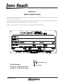
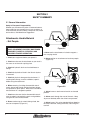
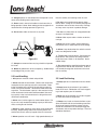
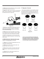
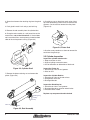
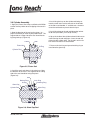
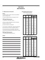
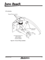
MAINTENANCE AND
SERVICE MANUAL
PHA
45-046, REV. 3/08
1
TABLE OF CONTENTS
SECTION
PAGE
SECTION PAGE
1
MODEL IDENTIFICATION ..............3
3
SERVICE PROCEDURE
2
SAFETY SUMMARY
2.1
2.2
2.3
2.4
GENERAL INFORMATION....................... 4
LOAD HANDLING................................... 5
LOAD POSITIONING............................... 5
OPERATION CONTROLS.........................6
3.1
3.2
3.3
3.4
3.5
3.6
ATTACHMENT REMOVAL........................7
CYLINDER REMOVAL............................. 7
CYLINDER INSTALLATION.......................7
CYLINDER DISASSEMBLY....................... 7
CYLINDER INSPECTION..........................8
CYLINDER ASSEMBLY............................ 9
4
MAINTENANCE
4.1
4.2
4.3
MAINTENANCE SCHEDULE.....................10
TORQUE SPECIFICATIONS.....................10
LUBRICATION...........................................11
2
45-046, REV. 3/08
SECTION 1
MODEL IDENTIFICATION
Each clamp is identified by a model number and a serial number located on the attachment nameplate which is attached to the
top of the unit prior to shipment.
Before ordering replacement parts for any unit, be sure to use the correct parts list for your model number. Both model number
and serial number must be given to ensure that the correct parts are ordered.
NOTE: The serial number is also metal stamped onto the plate under the identification plate.
PH A
Class II Mounting
Date Received:
-
45-046, REV. 3/08
-
Perry Hook
3
SECTION 2
SAFETY SUMMARY
2.1 General Information
Safety is Everyone’s Responsibility
Whether you are new on the job or a seasoned veteran,
these safety tips may prevent injury to you, to others, or
to the materials you are handling. Always be alert, watch
out for others, and follow these suggestions:
Attachments Handle Material
- Not People.
Safety starts with common sense.
GOOD JUDGEMENT, PROPERLY MAINTAINED
EQUIPMENT, CAREFUL OPERATION, AND
PROPERLY TRAINED OPERATORS.
1. Check your equipment before you operate it.
2. Check to make sure the attachment on your truck is
the same as on the truck capacity plate.
3. Check for hydraulic leaks and cracked hoses or
fittings.
Figure 2-1
9. Never use the attachment or its load to support a
man carrying device.
10. Never position an attachment or load over people.
(Figure 2-2)
4. Check the hydraulic oil level in the lift truck hydraulic reservoir.
5. Check for physical damage to the attachment. If
anything looks wrong, unusual or different, report it
before using the attachment.
6. When removing / installing dismountable attachments always keep hands and feet free from dangerous positions or pinch points. Never leave a dismounted attachment in a dangerous position.
7. Check to make sure that the dismountable attachment is properly secured to the truck carriage before
using the lift truck and attachment.
8. Never stand on top of material being raised, lowered, or transported. (Figure 2-1)
4
Figure 2-2
11. Never leave an attachment or load in an elevated
position.
12. Never reach through the mast of the truck. Keep
all parts of the body within the driver’s compartment.
13. Never leave a lift truck unattended without lowering
the load to the floor, setting the brake, and turning the
truck off.
45-046, REV. 3/08
14. Always operate an attachment from the operator’s seat,
never while standing next to the lift truck.
15. Never stand in front of or beside an attachment that is
being operated. Never allow another person to approach an
attachment that is being operated. (Figure 2-3)
16. Do not allow riders on the truck at any time.
fects the stability and steering of the lift truck.
6. Do not use an attachment to open or close
boxcar doors. Doing so can severely damage the
attachment and cause loss of warranty. Damage
to clamp arms may result in product damage.
7. Do not carry loose items or unsupported loads
on top of a clamped load.
8. Never allow anyone under a load or under the
carriage.
9. Never use chains, cables, or other devices in
conjunction with an attachment for load handling.
10. Never clamp loads other than what the attachment was designed to handle.
Figure 2-3
17. Always use reverse when carrying a load that impedes
full vision.
18. Watch for pedestrians when transporting. Sudden stops
can dislodge all or part of a load.
11. Travel slowly around corners. Sound horn on
blind corners. Be careful of tail swing and overhead clearances. Watch in all directions. Avoid
sudden stops.
12. Do not exceed the specified maximum operating pressure or flow for the attachment. To do so
can severely damage the attachment and cause
loss of warranty.
2.2 Load Handling
1. All operators must be trained and qualified.
2. Never overload the attachment. Refer to the attachment
nameplate for the rated capacity of the attachment. Refer
to the nameplate of the truck for the net working capacity
of the truck and attachment. Observe the lower of the two
capacities. The attachment capacity is the structural rating
of the attachment and should not be exceeded. Net working capacity is the truck manufacturer’s rating of the truck/
attachment combination.
3. Never use a load to support or move another object. Doing so can easily exceed the holding capacity of the attachment, causing loss of the load.
4. Never lift, lower, side shift, pivot, rotate, or tilt loads while
traveling. Repositioning loads while traveling affects the
stability of the truck and may impede vision or clearances.
2.3 Load Positioning
1. Always operate an attachment from the driver’s
seat.
2. Always lower the attachment if you need to
leave the lift truck. Remember a lift truck supporting a load requires your full attention.
3. Never use the attachment or its load to support
or move other loads or equipment.
4. Always carry loads as close to the floor as possible, consistent with the surface being traversed.
Scraping or bumping the floor surface with the
load or the attachment can severely damage the
attachment and cause product damage. The mast
should be tilted back.
5. Never speed or race a lift truck. High speed adversely af-
45-046, REV. 3/08
5
5. Always keep the load positioned as close as possible
to the horizontal center of the lift truck.
6. Always back down ramps or inclines. Driving forward
down a ramp or incline with a clamped load will lessen
the stability of the truck. (Figure 2-4)
2.4 Operator’s Controls
1. For clarity, the direction of arm movement is shown
on the control handle. To move the arms in the direction shown, pull the handle towards the operator. To
move the arms in the opposite direction, the push the
handle away from the operator.
Clamp
Fork Positioner
Figure 2-4
7. Do not cross dock boards or dock levelers with the
attachment or carriage fully lowered. Ramming the
front or rear of the attachment against a dock board
can cause severe damage.
8. Always check loads to be handled. If they are broken, unbalanced, loose, or too heavy, advise a supervisor or properly correct the situation prior to handling.
9. Limit lift truck movement to a minimum when high
stacking. Limit sideshift movement to a minimum when
high stacking.
10. Always be observant when high stacking. Look
for poorly stacked loads, overhead obstacles, broken
cartons, or damaged products in the stack.
Push / Pull
Rotate
Side Shift
Figure 2-5
Note: OSHA or state regulations may
require the installation of backrests.
We suggest that you check your application against those requirements.
11. Always carry cylindrically shaped loads in the vertical position, not the horizontal.
12. Always clamp loads with the contact pads, if applicable, not the arm or arm base.
13. Never rotate a load that is off center to the centerline of rotation. Severe damage to the rotator could
result.
14. Always check the attachment for proper fit and
engagement of the truck carriage.
6
45-046, REV. 3/08
SECTION 3
SERVICE PROCEDURE
3.1 Attachment Removal
3.3 Cylinder Installation
1. Position the attachment forks to the width of the
unit’s body.
1. Install the clevis pin and hair pin into the base end of
the cylinder.
2. Attach the hydraulic connections to the cylinder.
before disconnecting any hydraulic connections be sure to turn
off the trucks power and activate
the trucks hydraulic functions in
both directions to bleed off the
hydraulic pressure.
3. Extend the cylinder until the rod end hole lines up
with the mounting hole. Install the clevis pin and hair
pin into the rod end of the cylinder.
4. Turn on the trucks power and activate the positioning
cylinders several times to bleed out trapped air.
2. Disconnect the hydraulic connection for the attachment positioning at the side shift cylinder.
3. Slightly raise the truck carriage to allow the removal
of the lower retainer hooks.
when hydraulic service has been
performed, before returning attachment to service be sure to
activate the hydraulic functions
several times to bleed out trapped
air in the system.
4. Position the attachment on the edge of a pallet.
Lower the attachment so that the lower carriage bar
misses the pallet when lowered. Tilt the mast forward
to allow the carriage to disengage from the upper
mounting hooks and back away. If lowering onto a
floor, blocks of wood can be place under the body of
the attachment to raise the rear.
3.4 Cylinder Disassembly
5. To reinstall, follow the installation procedure in this
manual.
2. Clamp the cylinder lightly at the base end in a soft
jawed vise. Use a block or other support under the rod
end of the cylinder. (Figure 3-1)
1. Remove the cylinder from the attachment. See
removal instructions.
when hydraulic servicing has been
performed, before returning attachment to service be sure to
activate the hydraulic functions
several times to bleed out trapped
air in the system.
3.2 Cylinder Removal
1. Disconnect the hydraulic connections.
2. Remove the cylinder rod end hair pin and clevis
pin.
Figure 3-1, Cylinder Vise
3. Remove hair pin and clevis pin at the base end of
the cylinder.
45-046, REV. 3/08
7
3. Spread and remove the retaining ring from the gland
cap.
4. Push gland inward 1 inch and pry out lock ring.
8. Carefully pry up on the piston seals using a blunt
tip screw driver being careful not to scratch the seal
grooves. Cut the seals to remove from the piston.
(Figure 3-4)
5. Remove the rod assembly from the cylinder tube.
6. Clamp the rod assembly in a soft jawed vise on the
wrench flats, not on the rod surface.
A If the rod does
not have wrench flats use two pieces of wood on both
sides of the rod to prevent scaring. (Figure 3-2)
Figure 3-4, Piston Seal
9. Use the same procedure as above to remove the
seals from the gland cap.
3.5 Cylinder Inspection
Inspect the cylinder tube bore for:
1. Deep scratches or nicks.
2. Signs of galling or excessive wear.
3. Out-of-roundness or deformities of the barrel.
Inspect the Piston for:
1. Scratches or nicks on seal grooves.
2. Wear on O.D.
Figure 3-2, Cylinder Shaft
7. Remove the piston retaining nut and remove the
piston. (Figure 3-3)
Inspect the Cylinder Rod for:
1. Scratches or nicks on the rod surface.
2. Straightness of the rod.
3. Damaged threads.
Inspect the Gland Cap for:
1. Scratches or nicks in seal grooves.
2. Damaged threads or spanner wrench holes.
3. Excessive wear in bore.
Replace any component found to be bad.
Retaining Ring
Lock Ring
Gland Cap
Piston Nut
Piston
Figure 3-3, Rod Assembly
8
45-046, REV. 3/08
3.6 Cylinder Assembly
1. Spray the Piston, Gland Cap, and Seals with WD40
or other similar product to ease slipping of the seals in
place.
2. Note the direction of the seal on the piston. Improper installation will result in poor performance. The
cupped side or O-Ring side of the seal should be facing the gland cap. (Figure 3-5)
Piston
Seal
Piston Nut
O-Ring
Cylinder Rod
4. Install the gland cap on the cylinder rod being extremely careful not to cut the rod seal on the threads
of the rod or rod shoulder. If available use a sleeve to
cover the rod threads or plastic electrical tape.
5. Install the piston on the rod and tighten the locknut
to 90 ft-lbs (0.56 UNF), 22 ft-lbs (0.75 UNF).
6. Spray the inside of the cylinder tube with lubricant to
Seal
ease inserting the rod and piston. Insert
the rod and
piston into the cylinder tube.
Tap
the
rod
rub- Ring
Backup Ring in with a Lock
ber mallet if resistance is encountered.
O-Ring
Retaining
Capand spread retaining ring to
7. Press on theGland
lock ring
install onto the gland cap.
Wiper R
Cylinder Rod
Figure 3-5, Piston Seal
3. Install the seals and wipers in the gland cap. Note
the direction of the seals. The cupped side or O-Ring
side of the seal should be facing the piston.
(Figure 3-6)
Seal
Backup Ring
Gland Cap
O-Ring
B
Cylinder Rod
Lock Ring
Retaining Ring
Wiper Ring
Figure 3-6, Gland Cap Seal
45-046, REV. 3/08
9
SECTION 4
MAINTENANCE
4.1 Maintenance Schedule
Daily:
1. Visually inspect all hoses, fittings and cylinder for
signs of hydraulic leaks.
4.2 Torque Specifications
Unless otherwise specified
3!%'RADE#APSCREWS
Nominal
Size
Thread
Series
2. Visually inspect for external damage or cracks.
1/4
100 Hour Maintenance:
5/16
20 UNC
28 UNF
18 UNC
24 UNF
16 UNC
24 UNF
14 UNC
20 UNF
13 UNC
20 UNF
12 UNC
18 UNF
11 UNC
18 UNF
10 UNC
16 UNF
9 UNC
14 UNF
8 UNC
14 UNF
7 UNC
12 UNF
7 UNC
12 UNF
1. Complete the above daily checks.
2. Check all hoses and fittings for wear or damage.
Inspect for hydraulic leaks.
3. Check for loose or missing bolts.
4. On the forks and top hooks, check grease fittings to
ensure that they are clean and properly working.
5. Check wearstrips on the top hooks. Wearstrips
should be replaced before top hooks contact carriage.
200 Hour Maintenance:
1. Re-Torque top hook bolts per chart.
3/8
7/16
1/2
9/16
5/8
3/4
7/8
1
1-1/8
1-1/4
0.2500
0.3125
0.3750
0.4375
0.5000
0.5625
0.6250
0.7500
0.8750
1.0000
1.1250
1.2500
Torque (Ft-Lbs)
Dry
Lubed
K=0.20
K=0.15
8
6
10
7
17
13
19
14
31
23
35
26
49
37
55
41
75
57
85
64
110
82
120
91
150
115
170
130
265
200
295
225
430
320
475
355
645
485
720
640
795
595
890
670
1120
840
1240
930
3!%'RADE#APSCREWS
Notes:
Nominal
Size
Thread
Series
1/4
20 UNC
28 UNF
18 UNC
24 UNF
16 UNC
24 UNF
14 UNC
20 UNF
13 UNC
20 UNF
12 UNC
18 UNF
11 UNC
18 UNF
10 UNC
16 UNF
9 UNC
14 UNF
8 UNC
14 UNF
7 UNC
12 UNF
7 UNC
12 UNF
5/16
3/8
7/16
1/2
9/16
5/8
3/4
7/8
1
1-1/8
1-1/4
10
Inches
Inches
0.2500
0.3125
0.3750
0.4375
0.5000
0.5625
0.6250
0.7500
0.8750
1.0000
1.1250
1.2500
Torque (Ft-Lbs)
Dry
K=0.20
12
14
25
27
44
49
70
78
105
120
155
170
210
240
375
420
605
670
910
1020
1290
1440
1820
2010
Lubed
K=0.15
9
10
18
20
33
37
52
58
77
90
112
130
155
180
280
315
455
500
680
765
965
1080
1360
1500
45-046, REV. 3/08
4.3 Lubrication
Grease Fitting Locations
Grease Fitting
Locations
Use NLGI Grade No. 2
Multi-Purpose
Lithium Extreme
Pressure Grease
Figure 4.1, Grease Fitting Locations 45-046, REV. 3/08
11