1
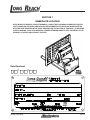
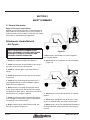
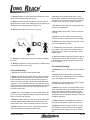
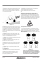
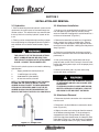
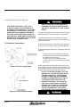
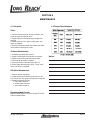
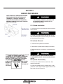
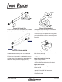
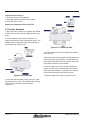
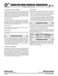
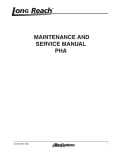
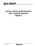
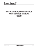
INSTALLATION, MAINTENANCE
AND SERVICE MANUAL
LP AND PLP
Ob
us sol
e 4 ete
5-0
69
45-042, REV. 05/10
1 of 12
TABLE OF CONTENTS
SECTIONPAGE
SECTIONPAGE
1
NAME PLATE LOCATION.............3
5
MAINTENANCE SCHEDULE
2
SAFETY SUMMARY
4.1
4.2
SCHEDULE..............................................9
TORQUE SPECIFICATIONS.................... 9
2.1
2.2
2.3
2.4
2.5
GENERAL INFORMATION....................... 4
LOAD HANDLING.................................... 5
LOAD POSITIONING............................... 5
HYDRAULICS...........................................6
OPERATOR’S CONTROLS...................... 6
5
SERVICE PROCEDURES
3
INSTALLATION & REMOVAL
5.1
5.2
5.5
5.6
5.7
CYLINDER INSTALLATION...................... 10
CYLINDER REMOVAL............................. 10
CYLINDER DISASSEMBLY...................... 11
CYLINDER INSPECTION......................... 11
CYLINDER ASSEMBLY............................ 12
3.1
3.2
3.3
3.4
TRUCK REQUIREMENTS...................... 7
ATTACHMENT INSTALLATION............... 7
HYDRAULICS.........................................7
ATTACHMENT REMOVAL..................... 8
2 of 12
45-042, REV. 05/10
SECTION 1
NAMEPLATE LOCATION
NOTE: WHEN YOU RECEIVE YOUR ATTACHMENT, LOCATE THE LONG REACH NAMEPLATE (UPPER
LEFT CORNER ON THE BODY) AND RECORD THE INFORMATION TO THE BLANK NAMEPLATE TAG
WITH THE DATE RECEIVED IN THE SPACE PROVIDED ON THE BOTTOM OF THIS PAGE. IF THE NAME
PLATE IS MISSING, LOOK FOR THE SERIAL NUMBER STAMPED DIRECTLY INTO THE METAL AT THE
ORIGINAL LOCATION AND CONSULT FACTORY.
Date Received:
-
45-042, REV. 05/10
-
3 of 12
SECTION 2
SAFETY SUMMARY
2.1 General Information
Safety is Everyone’s Responsibility
Whether you are new on the job or a seasoned veteran,
these safety tips may prevent injury to you, to others, or
to the materials you are handling. Always be alert, watch
out for others, and follow these suggestions:
Attachments Handle Material
- Not People.
SAFETY STARTS WITH COMMON SENSE.
GOOD JUDGEMENT, PROPERLY MAINTAINED
EQUIPMENT, CAREFUL OPERATION, AND
PROPERLY TRAINED OPERATORS.
1. Check your equipment before you operate it.
2. Check to make sure the attachment on your truck is
the same as on the truck capacity plate.
Figure 2-1
9. Never use the attachment or its load to support a
man carrying device.
10. Never position an attachment or load over people.
(Figure 2-2)
3. Check for hydraulic leaks and cracked hoses or
fittings.
4. Check the hydraulic oil level in the lift truck hydraulic reservoir.
5. Check for physical damage to the attachment. If
anything looks wrong, unusual or different, report it
before using the attachment.
6. When removing / installing dismountable attachments always keep hands and feet free from dangerous positions or pinch points. Never leave a dismounted attachment in a dangerous position.
7. Check to make sure that the dismountable attachment is properly secured to the truck carriage before
using the lift truck and attachment.
8. Never stand on top of material being raised, lowered, or transported. (Figure 2-1)
4 of 12
Figure 2-2
11. Never leave an attachment or load in an elevated
position.
12. Never reach through the mast of the truck. Keep
all parts of the body within the driver’s compartment.
13. Never leave a lift truck unattended without lowering
the load to the floor, setting the brake, and turning the
truck off.
45-042, REV. 05/10
14. Always operate an attachment from the operator’s seat,
never while standing next to the lift truck.
15. Never stand in front of or beside an attachment that is
being operated. Never allow another person to approach an
attachment that is being operated. (Figure 2-3)
6. Do not use an attachment to open or close
boxcar doors. Doing so can severely damage the
attachment and cause loss of warranty. Damage
to clamp arms may result in product damage.
7. Do not carry loose items or unsupported loads
on top of a clamped load.
16. Do not allow riders on the truck at any time.
8. Never allow anyone under a load or under the
carriage.
9. Never use chains, cables, or other devices in
conjunction with an attachment for load handling.
10. Never clamp loads other than what the attachment was designed to handle.
Figure 2-3
17. Always use reverse when carrying a load that impedes
full vision.
18. Watch for pedestrians when transporting. Sudden stops
can dislodge all or part of a load.
2.2 Load Handling
1. All operators must be trained and qualified.
2. Never overload the attachment. Refer to the attachment
nameplate for the rated capacity of the attachment. Refer
to the nameplate of the truck for the net working capacity
of the truck and attachment. Observe the lower of the two
capacities. The attachment capacity is the structural rating
of the attachment and should not be exceeded. Net working
capacity is the truck manufacturer’s rating of the truck/attachment combination.
3. Never use a load to support or move another object. Doing so can easily exceed the holding capacity of the attachment, causing loss of the load.
11. Travel slowly around corners. Sound horn on
blind corners. Be careful of tail swing and overhead clearances. Watch in all directions. Avoid
sudden stops.
12. Do not exceed the specified maximum operating pressure or flow for the attachment. To do so
can severely damage the attachment and cause
loss of warranty.
2.3 Load Positioning
1. Always operate an attachment from the driver’s
seat.
2. Always lower the attachment if you need to
leave the lift truck. Remember a lift truck supporting a load requires your full attention.
3. Never use the attachment or its load to support
or move other loads or equipment.
4. Always carry loads as close to the floor as possible, consistent with the surface being traversed.
Scraping or bumping the floor surface with the
load or the attachment can severely damage the
attachment and cause product damage. The mast
should be tilted back.
4. Never lift, lower, side shift, pivot, rotate, or tilt loads while
traveling. Repositioning loads while traveling affects the
stability of the truck and may impede vision or clearances.
5. Always keep the load positioned as close as
possible to the horizontal center of the lift truck.
5. Never speed or race a lift truck. High speed adversely
affects the stability and steering of the lift truck.
6. Always back down ramps or inclines. Driving
forward down a ramp or incline with a clamped
load will lessen the stability of the truck. (Figure
2-4)
45-042, REV. 05/10
5 of 12
7. Do not cross dock boards or dock levelers with the
attachment or carriage fully lowered. Ramming the
front or rear of the attachment against a dock board
can cause severe damage.
3. Assume that all hydraulic hoses and components
are pressurized. Relieve all hydraulic
pressure before disconnecting any hydraulic
line.
4. Never try to stop or check for a hydraulic leak
with any part of your body; use a piece of cardboard
to check for hydraulic leaks. Small hydraulic hose leaks
are extremely dangerous, and can inject hydraulic oil under the skin, even through gloves. Infection and gangrene
are possible when hydraulic oil penetrates the skin. See a
doctor immediately to prevent loss of limb or death.
Figure 2-4
8. Always check loads to be handled. If they are bro2.5 Operator’s Controls
ken, unbalanced, loose, or too heavy, advise a supervisor or properly correct the situation prior to handling.
1. For clarity, the direction of arm movement is shown
on the control handle. To move the arms in the direction
9. Limit lift truck movement to a minimum when high
shown, pull the handle towards the operator. To move
stacking. Limit sideshift movement to a minimum when the arms in the opposite direction, push the handle away
high stacking.
from the operator.
10. Always be observant when high stacking. Look
for poorly stacked loads, overhead obstacles, broken
cartons, or damaged products in the stack.
11. Always carry cylindrically shaped loads in the vertical position, not the horizontal.
12. Always clamp loads with the contact pads, if applicable, not the arm or arm base.
Clamp
Fork Positioner
13. Never rotate a load that is off center to the centerline of rotation. Severe damage to the rotator could
result.
14. Always check the attachment for proper fit and
2.4 Hydraulics
1. Be aware of the hazards of pressurized hydraulics:
2. Wear personal protective equipment, such as
gloves and safety glasses, whenever servicing
or checking a hydraulic system.
6 of 12
Push / Pull
Rotate
Side Shift
Figure 2-5
NOTE: OSHA OR STATE REGULATIONS MAY
REQUIRE THE INSTALLATION OF BACKRESTS.
WE SUGGEST THAT YOU CHECK YOUR APPLICATION AGAINST THOSE REQUIREMENTS.
45-042, REV. 05/10
SECTION 3
INSTALLATION AND REMOVAL
3.1 Hydraulics
3.2 Attachment Installation
1. Prior to connecting the truck hydraulic system to the
attachment, the system must be cleaned through the
filtration system. This will eliminate any contamination
that may exist in the auxiliary hydraulic system of the
truck.
1. Purging can be accomplished by installing a jumper
line and operating each hydraulic function (clamp,
rotate and side shift if equipped) in each direction for a
minimum of 30 seconds. (Figure 3-1)
2. Filtering can be accomplished by installing a jumper
line and operating each equipped hydraulic function in
each direction for a minimum of 30 seconds. (Figure
3-1)
2. Remove the lower bolt-on hooks and, if applicable,
make a note of any factory installed shims. If Quick
Change Hooks are equipped, simply depress the button on the back of the hooks, allowing the slide plate to
drop, Figure 3-2.
THE CAPACITY OF THE TRUCK AND ATTACHMENT COMBINATION MAY BE LESS THAN
THE CAPACITY SHOWN ON THE ATTACHMENT
ALONE. CONSULT TRUCK NAMEPLATE!
The lift truck hydraulic system must meet the following
specifications:
1.
Supply petroleum based hydraulic oil
2.
7-10 GPM (26.5-37.8 LPM)
3.
2200-2300 PSI (150-160 Bar)
4.
At least one auxiliary function
NOTE: IT IS THE RESPONSIBILITY OF THE DEALER AND /OR THE USER TO INSTALL THE REQUIRED VALVING TO MEET THE RECOMMENDED
HYDRAULIC PRESSURES AND FLOW. THE REQUIRED VALVING CAN BE FURNISHED BY THE
DEALER, THE TRUCK FACTORY, OR LONG REACH.
3. Center the truck behind the attachment and drive
toward the attachment with the mast tilted forward approximately 4°.
4. Line up the locking lug (if applicable) with the appropriate notch on the truck’s carriage. Check that the
bronze side-shifting wear strips are in the proper place,
if applicable.
5. Make sure the wear pad is in place and making
contact with lower carriage bar.
FAILURE TO CYCLE THE HYDRAULIC CIRCUIT
AS DESCRIBED ABOVE COULD CAUSE SERIOUS INJURY.
IF HYDRAULIC SUPPLY HOSES ARE DISCONNECTED, HYDRAULIC FLUID WILL LEAK OUT
AND PUSH PLATE MAY DRIFT OUTWARD.
3.4 Attachment Removal
1. Disconnect hydraulic connection at the attachment
from the truck.
2. Disconnect the Quick Mounts to remove the attachment. (Figure 3.2)
Figure 3-1, Jumper Line
45-042, REV. 05/10
3. Slightly raise the truck carriage to allow the removal
of the bottom mounting hooks. If the attachment is
equipped with Quick Change Hooks (Button-Type),
press the slide plate release button and drop the slide
plate down (Figure 3-2). If the attachment is equipped
with Quick Change Hooks (Pin-Type), remove the Re7 of 12
taining Pin and the Quick Change Hook.
THIS SLIDE PLATE MUST “CLICK” INTO
PLACE TO ENSURE THE ATTACHMENT IS
SECURED TO THE CARRIAGE. IF THE SLIDE
PLATE DOES NOT CLICK INTO PLACE, (BECAUSE THE TRUCK CARRIAGE PREVENTS
THE SLIDE PLATE FROM BEING RAISED UP
HIGH ENOUGH), SHIMS MUST BE INSTALLED
BETWEEN THE ATTACHMENT AND THE BODY
OF THE QUICK CHANGE HOOKS.
3.5 Hydraulic Connections
1. Install the lines from the truck’s hydraulics to the
hydraulics of the attachment.
ANY ALTERATIONS TO THE ORIGINAL ATTACHMENT MAY AFFECT PERFORMANCE
OR SAFETY AND RESULT IN LOSS OF WARRANTY.
2. Inspect installation to ensure hoses are not kinked or
pinched between the truck carriage and attachment.
3. Operate the attachment continuously for several
minutes to determine that all hydraulic connections are
secure with no leaks.
4. Activate cylinders fully and check that the truck’s hydraulic reservoir oil level is at the recommended level.
5. Before placing the attachment in operation check the
following:
Figure 3.2 Quick Change Hook
a. Inspect all hoses and fittings for leaks and routing clearance. Be sure to include clearance of jumper hoses to the mast.
b. Check the valve and cylinder for leaks.
c. Check cotter pins at each end of the cylinder for security.
6. After completing the installation, operate the attachment without a load for several cycles to remove any air
in the hydraulic system. Test the attachment with a load
to make sure the attachment operates correctly.
NOTE: IT IS THE RESPONSIBILITY OF THE
DEALER AND / OR THE USER EAITHER TO
FURNISH AND INSTALL THE REQUIRED
VALVING TO MEET THE RECCOMENDED
HYDRAULIC PRESSURES AND FLOW OR
TO ARRANGE INSTALLATION OF THE
REQUIRED VALVING AT THE TRUCK FACTORY OR AT LONG REACH. THE MODEL
DESCRIPTION, FOUND ON THE SHIPPING
INVOICE, WILL STATE THE FOLLOWING
TRUCK REQUIREMENTS: FLOW (GPM),
PSA, AND MIN, TRUCK CARRIAGE WIDTH.
Figure 3-3, Lower Hook Clearance
8 of 12
45-042, REV. 05/10
SECTION 4
MAINTENANCE
4.1 Schedule
4.2 Torque Specifications
Daily:
1. Visually inspect all hoses, fittings, cylinders, and
valves for signs of hydraulic leaks.
2. Inspect hoses for wear/pinching and replace as
required.
3. Inspect forks for nicks, dents, rough spots, and
repair as required.
4. Visually inspect lower hook installation and check
unit for external damage or cracks.
40 Hour Maintenance:
1. Complete the above daily checks.
2. Inspect retaining pins and replace as required.
3. Tighten mechanism pivot retaining pin bolts.
4. Lube bronze top hooks if needed.
5. Lube mechanism if desired. (Use Light Oil)
6. Check lower hook clearance (3/16” = 5mm maximum) and adjust as required.
Notes:
500 Hour Maintenance
1. Perform 40 hour inspection.
2. Inspect bushings for excessive clearance (1/32” =
1mm maximum) at all pivots and replace as required.
3. Tighten and torque all bolts.
a. Top Hooks: 225 N-m
b. Lower Hooks: 225 N-m
c. Fork Hooks: 225 N-m
Recommended Grease:
Mobile XHP222 Special, or similar quality EP-2 with
Lithium Complex Base.
45-042, REV. 05/10
9 of 12
SECTION 5
SERVICE PROCEDURES
WHEN HYDRAULIC SERVICING HAS BEEN
PERFORMED, BEFORE RETURNING ATTACHMENT TO SERVICE BE SURE TO
ACTIVATE THE HYDRAULIC FUNCTIONS
SEVERAL TIMES TO BLEED OUT TRAPPED
AIR IN THE SYSTEM.
BEFORE DISCONNECTING ANY HYDRAULIC CONNECTIONS BE SURE TO TURN
OFF THE TRUCK’S POWER AND ACTIVATE
THE TRUCK’S HYDRAULIC FUNCTIONS IN
BOTH DIRECTIONS TO BLEED OFF HYDRAULIC PRESSURE.
5.1 Cylinder Installation
1. Install the clevis pin and cotter pin into the base end
of the cylinder.
2. Attach the hydraulic connections to the cylinder.
3. Extend the cylinder until the rod end hole lines up
with the mounting hole. Install the clevis pin and cotter
pin into the end of the cylinder.
5.2 Cylinder Removal
1. Disconnect the hydraulic connections.
2. Remove the cylinder rod end cotter pin and clevis.
3. Remove cotter pin and clevis pin at the base of the
cylinder.
THIS SLIDE PLATE MUST “CLICK” INTO PLACE
Figure THE
5.2 Quick
ChangeIS
Hook
TO ENSURE
ATTACHMENT
SECURED
TO THE CARRIAGE. IF THE SLIDE PLATE
DOES NOT CLICK INTO PLACE, (BECAUSE
THE TRUCK CARRIAGE PREVENTS THE
SLIDE PLATE FROM BEING RAISED UP HIGH
ENOUGH), SHIMS MUST BE INSTALLED BETWEEN THE ATTACHMENT AND THE BODY OF
THE QUICK CHANGE HOOKS.
10 of 12
FAILURE TO CYCLE THE HYDRAULIC CIRCUIT
AS DESCRIBED ABOVE COULD CAUSE SERIOUS
INJURY.
5.3 Cylinder Disassembly
1. Remove the cylinder from the attachment. See
removal instructions.
2. Clamp the cylinder lightly at the base end in a soft
jawed vise. Use a block or other support under the rod
end of the cylinder. (Figure 5-3)
45-042, REV. 05/10
A
Figure 5-3, Cylinder Vise
3. Use a spanner wrench or similar tool to unscrew the
gland cap from the cylinder tube. (Figure 5-4)
Figure 5-5, Cylinder Shaft
6. Remove the piston retaining nut and remove the
piston. (Figure 5-4)
7. Carefully pry up on the piston seals using a blunt
tip screw driver being careful not to scratch the seal
grooves. Cut the seals to remove from the piston.
(Figure 5-6)
A
Figure 5-4, Cylinder Rebuild
4. Remove the rod assembly from the cylinder tube.
5. Clamp the rod assembly in a soft jawed vise on the
wrench flats, not on the rod surface. If the rod does
not have wrench flats use two pieces of wood on both
sides of the rod to prevent scarring. (Figure 5-8)
Figure 5-6, Piston Seal
8. Use the same procedure as above to remove the
seals from the gland cap.
5.4 Cylinder Inspection
Inspect the cylinder tube bore for:
1. Deep scratches or nicks.
2. Signs of galling or excessive wear.
3. Out-of-roundness or deformities of the barrel.
Inspect the Piston for:
1. Scratches or nicks on seal grooves.
2. Wear on O.D.
Inspect the Cylinder Rod for:
1. Scratches or nicks on the rod surface.
2. Straightness of the rod.
3. Damaged threads.
45-042, REV. 05/10
11 of 12
Inspect the Gland Cap for:
1. Scratches or nicks in seal grooves.
2. Damaged threads or spanner wrench holes.
3. Excessive wear in bore.
Replace any component found to be bad.
5.5 Cylinder Assembly
1. Spray the Piston, Gland Cap, and Seals with WD40
or other similar product to ease slipping of the seals in
place.
2. Note the direction of the seal on the piston. Improper installation will result in poor performance. The
cupped side or O-Ring side of the seal should be facing the gland cap. (Figure 5-10)
Figure 5-11, Gland Cap Seal
4. Install the piston on the rod and tighten the locknut
to 70-75 ft-lbs.
5. Spray the inside of the cylinder tube with lubricant to
ease inserting the rod and piston. Insert the rod and
piston into the cylinder tube. Tap the rod in with a rubber mallet if resistance is encountered.
6. Install the gland cap on the cylinder rod being extremely careful not to cut the rod seal on the threads
of the rod or rod shoulder. If available use a sleeve to
cover the rod threads or plastic electrical tape.
Figure 5-10, Piston Seal
7. Tighten the gland cap using a spanner wrench.
3. Install the seals and wipers in the gland cap. Note
the direction of the seals. The cupped side or O-Ring
side of the seal should be facing the piston.
(Figure 5-11)
12 of 12
45-042, REV. 05/10