1
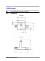
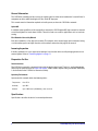
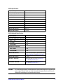
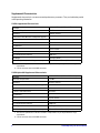
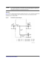
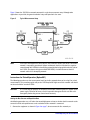
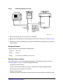
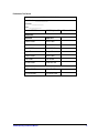
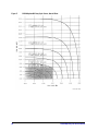
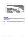
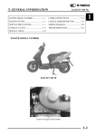
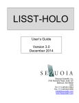
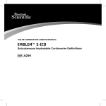
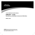
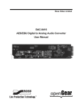
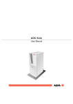
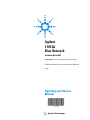
Agilent 11612A Bias Network Includes Option 001 Serial Numbers: This manual applies directly to Agilent 11612A Bias Networks with serial number prefix 2301A and higher. Operating and Service Manual Agilent Technologies Notices © Agilent Technologies, Inc. 1989, 2012, 2013 No part of this manual may be reproduced in any form or by any means (including electronic storage and retrieval or translation into a foreign language) without prior agreement and written consent from Agilent Technologies, Inc. as governed by United States and international copyright laws. Manual Part Number 11612-90001 Edition October 2013 Supersedes: September 2012 Agilent Technologies, Inc. 5301 Stevens Creek Blvd Santa Clara, CA 95051 Warranty The material contained in this document is provided “as is,” and is subject to being changed, without notice, in future editions. Further, to the maximum extent permitted by applicable law, Agilent disclaims all warranties, either express or implied, with regard to this manual and any information contained herein, including but not limited to the implied warranties of merchantability and fitness for a particular purpose. Agilent shall not be liable for errors or for incidental or consequential damages in connection with the furnishing, use, or performance of this document or of any information contained herein. Should Agilent and the user have a separate written agreement with warranty terms covering the material in this document that conflict with these terms, the warranty terms in the separate agreement shall control. Technology Licenses The hardware and/or software described in this document are furnished under a license and may be used or copied only in accordance with the terms of such license. Restricted Rights Legend If software is for use in the performance of a U.S. Government prime contract or subcontract, Software is delivered and licensed as “Commercial computer software” as defined in DFAR 252.227-7014 (June 1995), or as a “commercial item” as defined in FAR 2.101(a) or as “Restricted computer software” as defined in FAR 52.227-19 (June 1987) or any equivalent agency regulation or contract clause. Use, duplication or disclosure of Software is subject to Agilent Technologies’ standard commercial license terms, and non-DOD Departments and Agencies of the U.S. Government will receive no greater than Restricted Rights as defined in FAR 52.227-19(c)(1-2) (June 1987). U.S. Government users will receive no greater than Limited Rights as defined in FAR 52.227-14 (June 1987) or DFAR 252.227-7015 (b)(2) (November 1995), as applicable in any technical data. Safety Notices CAU TI O N A CAUTION notice denotes a hazard. It calls attention to an operating procedure, practice, or the like that, if not correctly performed or adhered to, could result in damage to the product or loss of important data. Do not proceed beyond a CAUTION notice until the indicated conditions are fully understood and met. WA RN ING A WARNING notice denotes a hazard. It calls attention to an operating procedure, practice, or the like that, if not correctly performed or adhered to, could result in personal injury or death. Do not proceed beyond a WARNING notice until the indicated conditions are fully understood and met. 11612A Bias Network NOTE In the following graphic, all dimensions are in millimeters. Figure 1 11612A Dimensions 11612A Operating and Service Manual 1 General Information The 11612A bias network provides a means of supplying dc bias to the center conductor of a coaxial line of a component or device while blocking the DC bias to the RF input port. This manual contains information required to install, operate, and test the 11612A bias network. Option 001 In addition to the capabilities of the standard bias network, the 11612A option 001 high current bias network can achieve higher bias levels above 0.4 GHz. These bias levels are useful in applications such as transistor testing. Bias Networks Covered by Manual Each bias network has a five digit serial number. The contents of this manual apply to bias networks having a serial number equal to or higher than the serial number listed on the title page of this manual. Incoming Inspection If the bias network or its case appear to be damaged, set aside the device and all packaging materials and contact Agilent. Refer to “Contacting Agilent” on page 11. Preparation For Use Interconnections The 11612A bias network is connected in line with the device to be biased. The bias is applied through the SMB snap-on connector. Refer to Figure 3 on page 6. A BNC to SMC adapter cable (part number 5062-4550) is also included in the 11612A bias network assembly. Operating Environment Operate the bias network within the following limits: Temperature 0 to +55 C Humidity up to 95% Altitude up to 7,625 meters (25,000 feet), mean sea level Specifications Specifications describe the device’s warranted performance. 2 11612A Operating and Service Manual 11612A Specifications Frequency Range 0.045 to 26.5 GHz Return Loss (both ports) – Minimum -- 0.045 to 8 GHz 20 dB 8 to 18 GHz 18 dB 18 to 26.5 GHz 14 dB Insertion Loss – Maximum -- 0.045 to 12.4 GHz 0.8 dB 12.4 to 26.5 GHz 1.3 dB Maximum Bias Current 500 mA Maximum Bias Voltage 40 Vdc 11612A Option 001 Specifications Frequency Rangea 0.4 to 26.5 GHz Return Loss (both ports) – Minimum -- 0.045 to 1 GHz 14 dB 1 to 18 GHz 18 dB 18 to 26.5 GHz 14 dB Insertion Loss – Maximum -- 0.4 to 12.4 GHz 1.0 dB 12.4 to 26.5 GHz 1.5 dB Maximum Bias Current 2 amps DC; up to 32 amps in pulsed mode. Refer to Figure 5 on page 10 and Figure 6 on page 11. Maximum Bias Voltage 100 Vdc Duty Cycle – Maximum Refer tothe duty cycle curves in Figure 5 on page 10 and Figure 6 on page 11. Pulse Width – Maximum Refer tothe duty cycle curves in Figure 5 on page 10 and Figure 6 on page 11. a. Operation below 0.4 GHz is possible but not specified. CAUTION It is critical that you properly set the power levels before connecting the bias network to the power supply. Failure to do so may result in irreparable damage to the bias coil. Bias coils damaged by overheating are not covered under warranty. 11612A Operating and Service Manual 3 Supplemental Characteristics Supplemental characteristics are non-warranted performance parameters. They are included to provide useful operating information. 11612A Supplemental Characteristics Pin Deptha 0.000 to 0.127 mm (0.0000 to 0.0050 inches) Maximum RF Input Power +24 dBm Impedance 50 ohms, nominal DC Resistance from Bias Port to Output Port (typical) -- At 23 C 0.5 ohms At 23 C, full rated current 0.7 ohms RF Connectors -- RF Input 3.5 mmb female RF Output 3.5 mm male Bias Connector (non-hermetic) SMB male Net Weight 0.075 kg (0.165 lb) Dimensions (nominal, not including connectors) 30 mm x 33 mm x 25 mm (1.2 in x 1.3 in x 1.0 in) a. The electrical performance of the bias network is independent of its pin depth within the range stated above. b. 3.5 mm connectors mate with SMA connectors. 11612A Option 001 Supplemental Characteristics Pin Deptha 0.000 to 0.127 mm (0.0000 to 0.0050 inches) Maximum RF Input Power +24 dBm Impedance 50 ohms, nominal DC Resistance from Bias Port to Output Port (typical) -- At 23 C 0.1 ohms At 23 C, full rated current 0.12 ohms RF Connectors -- RF Input 3.5 mmb female RF Output 3.5 mm male Bias Connector (non-hermetic) SMB male Net Weight 0.075 kg (0.165 lb) Dimensions (nominal, not including connectors) 30 mm x 33 mm x 25 mm (1.2 in x 1.3 in x 1.0 in) a. The electrical performance of the bias network is independent of its pin depth within the range stated above. b. 3.5 mm connectors mate with SMA connectors. 4 11612A Operating and Service Manual CAUTION It is critical that you properly set the power levels before connecting the bias network to the power supply. Failure to do so may result in irreparable damage to the bias coil. Bias coils damaged by overheating are not covered under warranty. Operation Figure 2 shows a schematic diagram of the bias network. The circuit is a “tee” in which the capacitor in the left arm acts as a DC block/high pass filter. The vertical arm, with its series inductance and shunt capacitance, acts as a low pass filter. Figure 2 Bias Network Schematic Diagram 11612A Operating and Service Manual 5 Figure 3 shows the 11612A bias network connected in a typical measurement setup. Although other applications are possible, the general method of setup and operation is the same. Figure 3 Typical Measurement Setup NOTE Transistors and negative resistance devices may oscillate if the bias port of the 11612A bias network is not properly terminated. Agilent recommends that bias from the bias supply be routed through the 11635A bias decoupling network before being applied to the bias port of the 11612A. An adapter cable (part number 5062-4550) is included to connect the bias network and the bias decoupling network. Instructions for Pulsed Operation (Option 001) The following procedure sets the correct power levels for the bias network when you’re using it for pulsed measurements. This procedure applies only to the 11612A option 001 high current bias network and should not be used with the standard 11612A. CAUTION It is critical that you properly set the power levels before connecting the bias network to the power supply. Failure to do so may result in irreparable damage to the bias coil. Bias coils damaged by overheating are not covered under warranty. Setting the Bias Current and Repetition Rate the following procedure uses a 0.1 ohm wire wound high power resistor to simulate the bias network so the correct bias level and repetition rate can be set before the bias network is connected. 1. Connect the equipment as shown in Figure 4 on page 7; do not connect the bias network yet. 6 11612A Operating and Service Manual Figure 4 11612A Option 001 Bias Level Setup 2. Measure the voltage across the resistor with an oscilloscope. 3. Set the current and repetition rate to the appropriate values (taken from the curve in Figure 6 on page 11.) 4. When the bias current and repetition rate are within the allowed limits, remove the resistor and insert the bias network. Storage and Shipment Store and ship the bias network within the following limits: Temperature –40 to +75 C Humidity up to 95% Altitude up to 7,625 meters (25,000 feet), mean sea level Returning a Device to Agilent If your device requires service, contact Agilent Technologies for information on where to send it. See “Contacting Agilent” on page 11. Include the following information: • your company name and address • a technical contact person within your company, and the person's complete telephone number • the part number and serial number of each device • the type of service required • a detailed description of the problem and how the device was being used when the problem occurred 11612A Operating and Service Manual 7 Performance Tests The procedures in this section test the electrical performance of the 11612A using the specifications listed in this document as performance standards. Record the results of the performance tests in the Performance Test Record, located at the end of the procedures. Return Loss of Input and Output Ports 1. Connect the equipment for a standard reflection measurement. 2. Calibrate the system with an open and a short. 3. Connect the appropriate RF port of the 11612A to the network analyzer test port. Terminate the opposite port with a 50 ohm load. NOTE The return loss of the terminating load should be at least 20 dB better than the desired measurement value. 4. Measure the return loss. Refer to the specifications listed in this document. Insertion Loss 1. Connect the equipment for a standard insertion loss measurement. 2. Calibrate the system with a through line. 3. Replace the through line with the 11612A. 4. Measure the insertion loss. Refer to the specifications listed in this document. 8 11612A Operating and Service Manual Performance Test Record ELECTRICAL SPECIFICATIONS Serial Number: ______________ Tested by: ______________ Date: ______________ Standard 11612A 11612A Option 001 Measured Value Return Loss Input Port Input Port 0.045 to 8 GHz 0.4 to 1 GHz 8 to 18 GHz 1 to 18 GHz 18 to 26.5 GHz 18 to 26.5 GHz Output Port Output Port 0.045 to 8 GHz 0.4 to 1 GHz 8 to 18 GHz 1 to 18 GHz 18 to 26.5 GHz 18 to 26.5 GHz Insertion Loss 0.045 to 12.4 GHz 0.4 to 12.4 GHz 12.4 to 26.5 GHz 12.4 to 26.5 GHz 11612A Operating and Service Manual 9 Figure 5 10 11612A Option 001 Duty Cycle Curves, Overall View 11612A Operating and Service Manual Figure 6 11612A Option 001 Duty Cycle Curves, Overall View Contacting Agilent Assistance with test and measurement needs and information on finding a local Agilent office are available on the Web at: www.agilent.com/find/assist NOTE In any correspondence or telephone conversation, refer to the Agilent product by its model number and full serial number. With this information, the Agilent representative can determine whether your product is still within its warranty period. 11612A Operating and Service Manual 11 12 11612A Operating and Service Manual