1
$'&6ROR
User Manual
© Agfa-Gevaert N.V. 1999.
No parts of this document may be reproduced, copied, adapted or transmitted in any form or by any means
without the written permission of Agfa-Gevaert N.V.
Agfa-Gevaert N.V. makes no warranties or representation, expressed or implied, with respect to the accuracy, completeness or usefulness of the information contained in this document and specifically disclaims
warranties of suitability for any particular purpose. Agfa-Gevaert N.V. shall under no circumstances be liable
for any damage arising from the use or inability to use any information, apparatus, method or process disclosed in this document.
Agfa-Gevaert N.V. reserves the right to make changes to this document without prior notice.
Agfa-Gevaert N.V., Septestraat 27, B-2640 Mortsel, Belgium.
ADC Solo is a trademark of Agfa-Gevaert N.V., Belgium.
Agfa and the Agfa-Rhombus are trademarks of Agfa-Gevaert AG, Germany.
2
2301A GB 19990507
Table of contents
&KDSWHU,QWURGXFLQJWKH$'&6ROR ...................................................................... 5
ADC Solo features ................................................................................................... 6
Safety precautions................................................................................................... 7
Safety compliance ................................................................................................... 8
Operating modes ..................................................................................................... 9
The user interface ................................................................................................. 10
Switching on the ADC Solo.................................................................................... 18
Switching off the ADC Solo.................................................................................... 20
&KDSWHU%DVLFRSHUDWLRQµ2SHUDWRUPRGH¶ ..................................................... 21
Reading an image plate......................................................................................... 22
Reading an emergency image plate ...................................................................... 24
Re-erasing an image plate .................................................................................... 28
&KDSWHU$GYDQFHGRSHUDWLRQµ.H\RSHUDWRUPRGH¶ ...................................... 31
Survey of advanced functions (‘Key-operator mode’) ............................................ 32
Preventive maintenance work................................................................................ 33
Troubleshooting checklist ...................................................................................... 34
$SSHQGL[$(TXLSPHQWLQIRUPDWLRQVKHHW .......................................................... 39
2301A GB 19990507
3
4
2301A GB 19990507
Chapter
Introducing the ADC Solo
This chapter draws attention to important safety precautions and
introduces the ADC Solo.
❑ ADC Solo features
❑ Safety precautions
❑ Safety compliance
❑ Operating modes
❑ The user interface
❑ Switching on the ADC Solo
❑ Switching off the ADC Solo
ADC Solo features
The ADC Solo is a digitizer for image plates retaining latent X-ray images. It has
been developed by Agfa.
■
The ADC Solo accepts one cassette containing one image plate at a time. The
ADC Solo:
• takes the cassette containing the image plate from the cassette slot;
• reads the cassette ID data;
• removes the image plate from the cassette;
• scans the image plate;
• converts the information of the latent image to digital data;
• erases the image plate and re-inserts it into the cassette;
• gives the cassette ID data the status ‘erased’;
• returns the cassette;
• transmits the digital image data to an image processing device (‘destination’).
6
■
The ADC Solo permits assigning the status ‘emergency’ to an image. An
emergency image will be given priority by the image processing device.
■
The ADC Solo permits re-erasing an image plate before re-using it. In specific
cases, this is necessary to prevent ghost images caused by previous exposures
or stray radiation from interfering with the image of interest.
2301A GB 19990507
Safety precautions
*HQHUDOVDIHW\LQVWUXFWLRQV
• The ADC Solo has been designed for scanning medical X-ray image plates and
should only be used for these purposes.
• The ADC Solo must only be operated by qualified staff.
• Make sure that the ADC Solo is constantly monitored in order to avoid inappropriate handling, especially by children.
• Only trained service personnel must make repairs. Only authorized service personnel must make changes to the ADC Solo.
• If there is any visible damage to the machine casing, do not start nor use the ADC
Solo.
• If you want to connect the ADC Solo with other devices, components or assemblies and if the technical data do not permit determining whether the combination
with these devices, components or assemblies involves hazards, you must consult
the respective manufacturers to avoid danger for operating personnel or the environment.
• Do not override or disconnect the integrated safety features.
• Switch off the ADC Solo before performing any maintenance work or repairs. Disconnect the ADC Solo from the mains before making repairs or performing any
maintenance activities during which live electrical components may be exposed.
• As is the case for all technical devices, the ADC Solo must be operated, cared for
and serviced correctly.
• If you don’t operate the ADC Solo correctly or if you don’t have it serviced correctly, Agfa-Gevaert is not liable for resulting disturbances, damages or injuries.
• When installing the ADC Solo, care must be taken to ensure that there is either a
mains plug or an all-cable disconnecting device in the internal installation fitted
near the ADC Solo and that it is easily accessible.
• If you notice conspicuous noise or smoke, disconnect the ADC Solo immediately.
• Check that the voltage setting of the machine matches the power supply voltage
before connecting the machine to the mains.
2301A GB 19990507
7
6DIHW\LQVWUXFWLRQVIRUODVHUSURGXFWV
The ADC Solo is a Class 1 Laser Product. Under normal operating conditions when the service doors are closed - there can be no laser radiation outside the
ADC Solo.
• Open the lower front door only to replace the erasure lamps or the fuses. Open
the right side panel only to solve cassette or image plate jams. When you open the
lower front door or the right side panel, the power supply is switched off automatically as a precaution.
• Follow meticulously the operation and troubleshooting instructions in the ADC
Solo User and Reference Manual. Other actions can be hazardous.
Safety compliance
The ADC Solo complies with:
• the general safety regulations EN 60950, EN 60601-1-2, UL 1950 and
CSA C22.2 No. 950;
• the radio interference regulations EN 55022:1997, Class B and FCC 47, Part 15,
Subchapter B, Class A;
• the laser safety regulations EN 60825-1:1994 and DHHS/FDA 21 CFR,
Parts 1040.10 and 1040.11.
8
2301A GB 19990507
Operating modes
The ADC Solo can be operated in three modes: operator mode, key-operator
mode, and service mode.
2SHUDWRUPRGH
The operator mode groups all basic functions which are aimed at radiographers:
• Reading an image plate;
• Reading an emergency image plate;
• Re-erasing an image plate.
A normal image plate is read automatically after it is inserted in the ADC Solo
cassette slot; the other functions of the operator mode can be accessed via the
keypad. All functions of the operator mode are described in &KDSWHU µ%DVLF
RSHUDWLRQµ2SHUDWRUPRGH¶¶.
.H\RSHUDWRUPRGH
The key-operator mode groups advanced functions which are aimed at technicians.
The key-operator mode can be accessed via the Key-operator key on the keypad
and is menu-driven. The key-operator functions are described in &KDSWHU µ$GYDQFHGRSHUDWLRQµ.H\RSHUDWRUPRGH¶¶ of the ADC Solo Reference manual.
6HUYLFHPRGH
The service mode functions are reserved for trained service personnel. They are
pass-word protected.
2301A GB 19990507
9
The user interface
The ADC Solo has three operation modes:
• the RSHUDWRUPRGH for basic operation;
• the NH\RSHUDWRUPRGH for advanced operation;
• the VHUYLFHPRGHreserved for trained service personnel.
The functions of the operator mode are described in &KDSWHUµ%DVLFRSHUDWLRQ
µ2SHUDWRU PRGH¶¶. An overview of the functions of the key-operator mode is
given in µ6XUYH\RIDGYDQFHGIXQFWLRQVµ.H\RSHUDWRUPRGH¶¶RQSDJH. For
detailed information on the key-operator mode, refer to the ADC Solo Reference
manual.
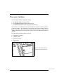
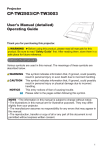
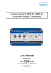
The ADC Solo interfaces with the user via:
• a keypad and a display;
• a status indicator;
• emergency buttons;
• audio signals.
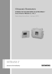
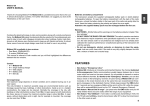
To access the keypad and the
display, press the ribbed area.
10
2301A GB 19990507
1 2
2301A GB 19990507
3
Status indicator
Emergency buttons
Keypad and display
11
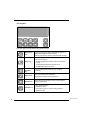
7KHNH\SDG
The ADC Solo keypad features the following keys:
12
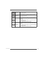
(PHUJHQF\
key
To give an image the status ‘emergency’ when it is
sent to the image processing device.
This key can only be used for cassettes with ID data.
(UDVH key
To erase images without digitizing them.
This must be done if:
• an image plate has not been used for more than
3 days;
• an image plate has been exposed to an
exceptionally high X-ray dose.
.H\
RSHUDWRU
key
To access advanced functions (‘key-operator
functions’).
6HUYLFH key
To access service-level functions.
Reserved for trained service personnel.
(VFDSH key
To quit the current function or exit a menu without
saving modifications.
&RQILUP key
In key-operator mode:
• to select a menu.
• to accept an entry in a menu and go back to
operator mode.
2301A GB 19990507
2301A GB 19990507
8S key
• To move the cursor to the previous entry field.
• To scroll upwards.
• To increment the number in a numeric entry field.
'RZQ key
• To move the cursor to the next entry field.
• To scroll downwards.
• To decrement the number in a numeric entry field.
/HIW key
• To scroll backwards through multiple choices within
a field.
• To move the entry position in a numerical entry field
from right to left.
• To toggle between values in a field.
5LJKW key
• To scroll forwards through multiple choices within a
field.
• To move the entry position in a numerical entry field
from left to right.
• To toggle between values in a field.
13
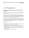
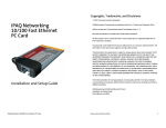
7KHGLVSOD\
The ADC Solo control panel has a backlit LCD display with 8 lines of 40 characters each. Its lay-out depends on the operating mode.
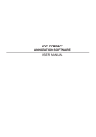
◆ In RSHUDWRUPRGH, the display has dedicated areas for specific information:
2
1
Set-up display
3
4
STATUS
FUNCTION MODE
5
670(66$*($55$<
QG0HVVDJH$UUD\
8.1
8.2
8.3
Patient_Last_Name
Patient_Last_Name
Patient_Last_Name
Station Name
Sub_Exam
Sub_Exam
Sub_Exam
ERROR
6
7
Set-up of image processing device:
•
•
•
•
[blank]: Default image processing device selected.
Off line: Transmission to all image processing devices disabled.
[process.station] not ready: Image processing device not available.
[process.station] rerouted: Images rerouted to other image processing
device.
Type of message
Extra comment or action to take
System status:
• READY: The ADC Solo is ready for operation.
• BUSY: The ADC Solo is treating an image plate.
• ERROR: An error has occurred. Refer to µ7URXEOHVKRRWLQJFKHFNOLVW¶RQ
SDJH.
• LOCKED: id.
• WARNING: id.
Operation mode:
• [blank]: Normal operation mode.
• EMERGENCY: Emergency function for image plates with ID data.
• EMERGENCY BUTTON: Emergency function for image plates without
ID data.
• ERASURE: Re-erasure function.
14
Error status: service code (SERVICE XXXXX) or error code (CODE XXXXX)
Device name of the ADC Solo
2301A GB 19990507
Identifier of image plate being treated:
After image ID data is read;
During scanning of image plate and transmittal of image data;
During transmittal of image data to image processing device.
The operator main screen is:
READY
ADC SOLO
When the ADC Solo is treating an image plate, it displays the following screen:
BUSY
Miller
Chest AP
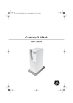
◆ In NH\RSHUDWRU PRGH, operation is menu driven. The menu displays the keyoperator functions, the active keys, and the service code.
Queue management
Digitizer set-up
Date and Time
Send test image
System info
Install
Save configuration
1
KEY-OPERATOR
MENU
: quit
: ok
: select
SERVICE XXXXX
Key-operator functions
Active keys
Service code
2
3
◆ In RSHUDWRU PRGH and in NH\RSHUDWRU PRGH, both informational and warning
messages can be displayed. Informational messages are displayed as black text
against a white background; warning messages are displayed in reverse mode.
2301A GB 19990507
15
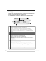
7KHVWDWXVLQGLFDWRU
At the top of the ADC Solo, a light indicates the status of the ADC Solo.
&RORU
&RQVWDQW
6WDWXV
)ODVKLQJ
$FWLRQ
&RQVWDQW
Ready
Proceed
)ODVKLQJ
Busy (treating image
plate)
Wait
&RQVWDQW
Error
• Check display for messages
• Refer to µ7URXEOHVKRRWLQJ
FKHFNOLVW¶RQSDJH.
)ODVKLQJ
• Locked or warning
• Power on/self-test in
progress
• Key-operator mode
• Service mode
• ADC Solo not
connected to image
processing device
*UHHQ
5HG
• Check display for messages
• Refer to µ7URXEOHVKRRWLQJ
FKHFNOLVW¶RQSDJH.
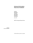
(PHUJHQF\EXWWRQV
Two emergency buttons are located at the front of the ADC Solo. They permit
processing emergency image plates without ID data. The upper button permits
processing of emergency images of the trunk; the lower button permits processing of emergency images of the limbs.
The emergency buttons have the following labels:
For digitizing unidentified emergency images of the trunk.
For digitizing unidentified emergency images of the limbs.
16
2301A GB 19990507
$XGLRVLJQDOV
The ADC Solo gives status information via beeps. The length of the beep indicates the response of the system to a key command.
• A VKRUW beep means that ADC Solo has accepted the key command and is starting the operation.
• A ORQJ beep means that you have pressed a non-active key or that the ADC Solo
has rejected the key command.
• An LQWHUYDO beep accompanies an error, locked or warning message. Refer to
µ7URXEOHVKRRWLQJFKHFNOLVW¶RQSDJH.
2301A GB 19990507
17
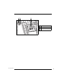
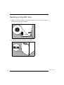
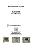
Switching on the ADC Solo
1
Make sure that the setting of the voltage selector at the back of the machine
matches the power supply voltage.
120
230-240
100
2
18
Locate the main switch and place it in position ‘I’.
2301A GB 19990507
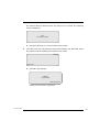
The machine starts a self-test which may take up to 3 minutes. The following
screen is displayed:
WAIT
Self test proceeding
❖
3
'XULQJWKHVHOIWHVW\RXFDQQRWDFWLYDWHDQ\IXQFWLRQV
If the ADC Solo has completed the self-test successfully, the ADC Solo enters
the operator mode and displays the operator main screen:
READY
ADC SOLO
❖
,IWKH$'&6RORGLVSOD\V
ERROR
Self test failed
SERVICE XXXXX
FRQWDFW\RXUORFDOVHUYLFHRUJDQL]DWLRQ
2301A GB 19990507
19
Switching off the ADC Solo
%HIRUHVZLWFKLQJRII
Check that the ADC Solo is not scanning an image plate. If the ADC Solo is
scanning an image plate, the status indicator at the top of the machine is green
and flashing.
6ZLWFKLQJRII
It is recommended to switch off the ADC Solo at the end of the day.
2QO\ VZLWFK RII WKH $'& 6ROR LI \RX GR QRW LQWHQG WR GLJLWL]H HPHUJHQF\
LPDJH SODWHV RYHUQLJKW 6ZLWFKLQJ RQ WKH $'& 6ROR WDNHV DSSUR[LPDWHO\
PLQXWHV'XULQJWKLVWLPHHPHUJHQF\GLJLWL]LQJLVQRWSRVVLEOH
Place the main switch in position ‘0’.
20
2301A GB 19990507
Chapter
Basic operation
(‘Operator mode’)
This chapter provides basic information on how to digitize image
plates under normal conditions and in emergency situations. It
also treats how to re-erase an image plate to prevent ghost
images caused by previous exposures or by stray radiation.
These functions are available in operator mode.
❑ Reading an image plate
❑ Reading an emergency image plate
❑ Re-erasing an image plate
Reading an image plate
The main function of the ADC Solo is digitizing image plates and transmitting
digital image data to an image processing device.
To read an image plate:
1
Make sure the cassette has been identified properly via the ID station.
2
Check that the ADC Solo is ready for operation:
• the ADC Solo must display the operator main screen with ‘Ready’ status, e.g.:
VIPS not ready
READY
Status field
ADC SOLO
• the status indicator at the top of the ADC Solo must be green and be lit constantly.
❖
3
7KH$'&6RORLVRSHUDWLRQDOLIWKHVWDWXVILHOGHTXDOVµ5($'<¶HYHQLIVWDWXV
PHVVDJHVRIWKHGHVWLQDWLRQDUHVKRZQHJµ9,36QRWUHDG\
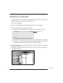
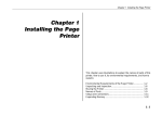
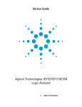
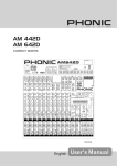
Insert the cassette containing the image plate into the cassette slot of the ADC
Solo as shown below.
Make sure to insert the cassette with the hinge [1] at the top and the locking mechanism [2] at the bottom.
1
2
22
2301A GB 19990507
While treating the image plate, the ADC Solo will display the following screen:
BUSY
Miller
Chest AP
ADC SOLO
The ADC Solo:
• converts the information of the latent image to digital data;
• erases the image plate and re-inserts it into the cassette;
• gives the cassette ID data the status ‘erased’;
• returns the cassette;
• transmits the digital image data to an image processing device (‘destination’).
When the ADC Solo has treated the cassette, it displays the operator main screen.
:KHQ WKH $'& 6ROR UHWXUQV WKH FDVVHWWH LW LV UHDG\ WR EH UHXVHG LPPHGL
DWHO\ +RZHYHU LI \RX OHDYH LW IRU PRUH WKDQ GD\V EHIRUH UHXVLQJ LW \RX
PXVWUHHUDVHLWILUVW5HIHUWRµ5HHUDVLQJDQLPDJHSODWH¶RQSDJH
❖
2301A GB 19990507
If the $'&6ROR displays an error message, refer to ‘Troubleshooting checklist’ on page 34.
23
Reading an emergency image plate
You may have an image plate which you wish to give priority over other image
plates which are being processed by the image processing device. Such image
plates are referred to as ’emergency image plates’. In operator mode, you can
treat either:
◆ emergency image plates with ID data via the Emergency key on the keypad;
◆ emergency image plates without ID data via the emergency buttons at the front
of the ADC Solo.
5HDGLQJHPHUJHQF\LPDJHSODWHVZLWK,'GDWD
To read an emergency image plate with ID data:
1
Check that the ADC Solo is ready for operation:
• the ADC Solo must display the operator main screen with ‘Ready’ status, e.g.:
VIPS not ready
READY
Status field
ADC SOLO
• the status indicator at the top of the ADC Solo must be green and be lit constantly.
❖
24
7KH$'&6RORLVRSHUDWLRQDOLIWKHVWDWXVILHOGHTXDOVµ5($'<¶HYHQLIVWDWXV
PHVVDJHVRIWKHGHVWLQDWLRQDUHVKRZQHJµ9,36QRWUHDG\
2301A GB 19990507
2
Press the Emergency key on the keypad.
The display will read:
READY
EMERGENCY
:$51,1*
1H[WFDVVHWWHJHWVHPHUJHQF\VWDWXV
ADC SOLO
7KH HPHUJHQF\ VWDWXV ZLOO RQO\ EH DVVLJQHG WR WKH ILUVW LPDJH SODWH ZKLFK
\RX LQVHUW LQWR WKH $'& 6ROR FDVVHWWH VORW DIWHU SUHVVLQJ WKH (PHUJHQF\
NH\
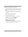
3
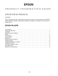
Insert the cassette containing the emergency image plate into the cassette slot
as shown below.
Make sure to insert the cassette with the hinge [1] at the top and the locking mechanism [2] at the bottom.
1
2
When the ADC Solo has treated the emergency image plate, it displays the operator
main screen.
❖
2301A GB 19990507
,I\RXGRQRWHQWHUDFDVVHWWHZLWKLQPLQXWHDIWHUSUHVVLQJWKH(PHUJHQF\
NH\ RU LI \RX HQWHU D FDVVHWWH ZLWKRXW ,' GDWD WKH $'& 6ROR ZLOO TXLW WKH
HPHUJHQF\IXQFWLRQDQGUHWXUQWRWKHRSHUDWRUPDLQVFUHHQ
25
5HDGLQJHPHUJHQF\LPDJHSODWHVZLWKRXW,'GDWD
To read an emergency image plate without ID data:
1
Check that the ADC Solo is ready for operation:
• the ADC Solo must display the operator main screen with ‘Ready’ status, e.g.:
READY
Status
ADC SOLO
• the status indicator at the top of the ADC Solo must be green and be lit constantly.
2
Press one of the emergency buttons at the front of the ADC Solo.
For digitizing unidentified emergency images of the trunk.
For digitizing unidentified emergency images of the limbs.
The button which you have pressed will be lit and the display will read:
READY
EMERG. BUTTON
:$51,1*
3OHDVHHQWHUXQLGHQWLILHGFDVVHWWH
ADC SOLO
7KH HPHUJHQF\ VWDWXV ZLOO RQO\ EH DVVLJQHG WR WKH ILUVW LPDJH SODWH ZKLFK
\RX LQVHUW LQ WKH $'& 6ROR FDVVHWWH VORW DIWHU SUHVVLQJ WKH HPHUJHQF\ EXW
WRQ
26
2301A GB 19990507
3
Insert the cassette containing the emergency image plate into the cassette slot
as shown below.
Make sure to insert the cassette with the hinge [1] at the top and the locking mechanism [2] at the bottom.
1
2
The image plate will be digitized using the scan parameters for the emergency button
as defined during configuration.
When the ADC Solo has treated the emergency image plate, it displays the operator
main screen. The digital image data are transmitted to the image processing device
accompanied by default ID data. The image processing device will give the emergency image priority over the other images in the image processing queue.
2301A GB 19990507
❖
,I \RX GR QRW HQWHU D FDVVHWWH ZLWKLQ VHFRQGV DIWHU SUHVVLQJ WKH HPHU
JHQF\ EXWWRQ WKH $'& 6ROR ZLOO TXLW WKH HPHUJHQF\ EXWWRQ IXQFWLRQ DQG
UHWXUQWRWKHRSHUDWRUPDLQVFUHHQ
❖
7R FKDQJH WKH VFDQ SDUDPHWHUV FRUUHVSRQGLQJ WR WKH HPHUJHQF\ EXWWRQ
FRQWDFW\RXUORFDOVHUYLFHRUJDQL]DWLRQ
27
Re-erasing an image plate
At the end of a normal or emergency digitizing cycle, the ADC Solo returns an
erased image plate. However, in the following cases, you must re-erase the
image plate before re-using it in order to prevent ghost images from interfering
with the image of interest:
• If the image plate has not been used for more than 3 days.
In this case, the image plate may have been exposed to stray radiation.
• If an image plate has been exposed to an exceptionally high X-ray dose.
In this case, deep layers of the image plate may still retain a latent image after
standard erasure. Leave the image plate to rest at least one day before re-erasing
it.
You can erase image plates which you have given the status ‘to be erased’ via
the ID station or image plates which have the status ‘erased’.
5HHUDVLQJLPDJHSODWHVZLWKVWDWXVµHUDVHG
To re-erase an image plate which has been erased as part of a normal or emergency digitizing cycle:
1
Check that the ADC Solo is ready for operation:
• the ADC Solo must display the operator main screen with ‘Ready’ status, e.g.:
READY
Status
ADC SOLO
• the status indicator at the top of the ADC Solo must be green and be lit constantly.
2
28
Press the Erase key on the keypad.
2301A GB 19990507
The display will read:
READY
ERASURE
:$51,1*
7KHQH[WFDVVHWWHZLOOEHHUDVHG
Put cassette in slot or press
3
to quit
Insert the cassette into the cassette slot.
While erasing, the ADC Solo will still display the above screen. When the ADC Solo
has erased the image plate, it displays the operator main screen.
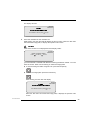
:DUQLQJ
If the above screen is not displayed but the display reads:
LOCKED
ERASURE
ERASE “PATIENT NAME”?
Press
to erase or
to scan
you have entered a cassette with ID data not having the status ‘erased’. You now
have the choice: either cancel erasing or erase the image plate.
◆ To cancel erasing and make a regular scan: press the Escape key.
◆ To erase the image plate: press the Confirm key.
While erasing, the ADC Solo will display:
READY
ERASURE
:$51,1*
7KHQH[WFDVVHWWHZLOOEHHUDVHG
Put cassette in slot or press
to quit
When the ADC Solo has erased the image plate, it displays the operator main
screen.
2301A GB 19990507
29
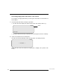
5HHUDVLQJLPDJHSODWHVZLWKVWDWXVµWREHHUDVHG
To re-erase an image plate which you have given the status ‘to be erased’ via
the ID station:
1
Check that the ADC Solo is ready for operation:
• the ADC Solo must display the operator main screen with ‘Ready’ status, e.g.:
READY
Status
ADC SOLO
• the status indicator at the top of the ADC Solo must be green and be lit constantly.
2
Insert the cassette into the cassette slot.
The ADC Solo will automatically erase the image plate. The display will read:
BUSY
* * * ERASING * * *
When the ADC Solo has erased the image plate, it displays the operator main
screen.
30
2301A GB 19990507
Chapter
Advanced operation
(‘Key-operator mode’)
This chapter gives an overview of the key-operator functions,
preventive maintenance actions and troubleshooting.
For detailed information on these topics, refer to the Reference
Manual.
❑ Survey of advanced functions (‘Key-operator mode’)
❑ Preventive maintenance work
❑ Troubleshooting checklist
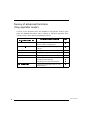
Survey of advanced functions
(‘Key-operator mode’)
A survey of the functions which are available in key-operator mode is given
below. For detailed information, refer to &KDSWHUµ$GYDQFHGRSHUDWLRQµ.H\
RSHUDWRUPRGH¶¶ of the ADC Solo Reference manual.
)XQFWLRQLQ
NH\RSHUDWRUPDLQPHQX
6HFWLRQLQ5HIHUHQFH0DQXDO
&RQVXOWLQJWKHLPDJHWUDQVPLVVLRQ
TXHXHµ4XHXHPDQDJHPHQW¶.
&XVWRPL]LQJWKH$'&6RORµ'LJLWL]HU
VHWXS¶.
'DWHDQG7LPH
6HWWLQJWKHGDWHDQGWLPH.
6HQGWHVWLPDJH
6HQGLQJWHVWLPDJHV.
6\VWHPLQIR
&RQVXOWLQJLQIRUPDWLRQRQWKH$'&6ROR.
,QVWDOO
,QVWDOOLQJDQHZVRIWZDUHYHUVLRQ.
4XHXHPDQDJHPHQW
'LJLWL]HUVHWXS
,QVWDOOLQJDQHZODQJXDJH.
,QVWDOOLQJQHZFXVWRPHUSDUDPHWHUV.
6DYHFRQILJXUDWLRQ
32
3DJH
6DYLQJWKHFRQILJXUDWLRQGDWDRQDGLV
NHWWHEDFNXS.
2301A GB 19990507
Preventive maintenance work
The only maintenance action which you must perform is checking the image
quality. Refer to the Reference manual of the image processing system.
2301A GB 19990507
33
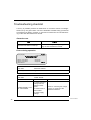
Troubleshooting checklist
A survey of possible problems is listed below. If corrective actions are straightforward, they are given below. The more elaborate troubleshooting procedures
are explained in detail in &KDSWHUµ3UHYHQWLYHPDLQWHQDQFHDQGWURXEOHVKRRW
LQJ¶ of the ADC Solo Reference manual.
*HQHUDOHUURUV
(UURU
$FWLRQ
The ADC Solo does not start up.
Refer to µ&KHFNLQJWKHYROWDJHVXSSO\¶RQ
SDJH of the Reference manual.
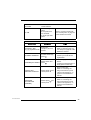
(UURUVGXULQJRSHUDWLRQ
Set-up display
67$786
FUNCTION MODE
670(66$*($55$<
QG0HVVDJH$UUD\
Patient_Last_Name
Patient_Last_Name
Patient_Last_Name
Station Name
6WDWXVILHOG
Error field:
Sub_Exam
Sub_Exam
Sub_Exam
(5525
(5525
‘SERVICE XXXXX’
Contact your local service organization.
6WDWXVILHOG
Error field:
0(66$*(
POWER SUPPLY OUT
OF TOLERANCE
(5525
‘CODE XXXXX’
0HVVDJH
1. Check setting of
voltage selector
switch on back
panel.
2. Check fuses of
the machine
$FWLRQ
Refer to µ&KHFNLQJWKHYROWDJH
VXSSO\¶RQSDJH of the
Reference manual.
3. Check supply
voltage.
34
2301A GB 19990507
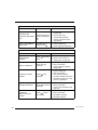
6WDWXVILHOG
Error field:
(5525
‘CODE XXXXX’
IP JAM
1. Remove right side
panel
2. Put plate back
into cassette.
3. Close right side
panel.
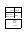
6WDWXVILHOG
0(66$*(
:$51,1*
0HVVDJH
$FWLRQ
ERASURE LAMP
[X], [Y], [Z] DEFECTIVE
Press to
complete, IP is not
erased
• Press Confirm key.
• Refer to µ5HSODFLQJWKHHUD
VXUHODPSV¶RQSDJH of the
Reference manual.
SCANNER WARNING
Possible bad image,
press
• Press Confirm key.
• Contact your local service
organization.
[PPNAME] NOT READY
Please check and
press
• Check image processing
device.
• If image processing device is
ready, press Confirm key.
CORRUPTED
MESSAGE IN QUEUE
UNKNOWN
DESTINATION
[PPNAME]
2301A GB 19990507
Refer to µ6ROYLQJLPDJHSODWH
DQGFDVVHWWHMDPV¶RQSDJH
of the Reference manual.
Please press
check queue
Please press
check queue
and
and
• Press Confirm key.
• Refer to µ&RQVXOWLQJWKH
LPDJHWUDQVPLVVLRQTXHXH
µ4XHXHPDQDJHPHQW¶¶RQ
SDJH of the Reference
manual.
• Press Confirm key.
• Refer to µ&RQVXOWLQJWKH
LPDJHWUDQVPLVVLRQTXHXH
µ4XHXHPDQDJHPHQW¶¶RQ
SDJH of the Reference
manual.
35
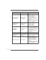
6WDWXVILHOG
0(66$*(
0HVVDJH
ERROR WHILE
LOADING LANGUAGE
FILE
Default language is
used, please press
PARTLY SCANNED IP
DETECTED
Possible loss of
image, press
6WDWXVILHOG
/2&.('
0(66$*(
36
:$51,1*
$FWLRQ
• Press Confirm key. English
will be used.
• Restart ADC Solo.
• If the problem persists,
contact your local service
organization.
• Press Confirm key.
• Check image at destination.
0HVVDJH
IP NOT
SUFFICIENTLY
ERASED
Press
again
EMPTY CASSETTE
Press to get
cassette
and erase
$FWLRQ
• Press Confirm key.
• Refer to µ5HHUDVLQJDQ
LPDJHSODWH¶RQSDJH’.
• Press Confirm key.
• Remove cassette.
• Insert cassette containing
image plate.
•
•
•
•
Press Confirm key.
Remove cassette.
Use another cassette.
If problem persists with other
cassettes, contact your local
service organization.
CASSETTE WRITE
ERROR
Press to get
cassette
WRONG CASSETTE
Press and remove
cassette.
• Press Confirm key.
• Remove cassette.
• Insert correct cassette in the
right way.
CASSETTE
IDENTIFICATION
ERROR
Press , remove
and identify
•
•
•
•
Press Confirm key.
Remove cassette.
Re-identify cassette.
Re-insert cassette.
2301A GB 19990507
6WDWXVILHOG
0(66$*(
0HVVDJH
$FWLRQ
•
•
•
•
Press Confirm key.
Remove cassette.
Re-insert cassette.
If problem persists, initialize
and identify cassette via ID
station.
• If problem persists with other
cassettes, contact your local
service organization.
CASSETTE READ/
WRITE ERROR
Press , remove
and try again
CASSETTE NOT
IDENTIFIED
Press , remove
and identify
•
•
•
•
24 X 30 CM
CALIBRATION
MISSING
Press
or
• Press Confirm key to treat
24 x 30 cm image plate without calibration or press Cancel key to treat cassettes with
other formats.
• Contact your local service
organization.
SERVICE MODE
Please wait
Wait.
CASSETTE SLOT
BLOCKED
Remove cassette,
press
• Remove cassette.
• Remove obstructing objects.
• Press Confirm key.
Check queue
• Refer to µ&RQVXOWLQJWKH
LPDJHWUDQVPLVVLRQTXHXH
µ4XHXHPDQDJHPHQW¶¶RQ
SDJH of the Reference
manual.
• Check that the ADC Solo is
not off line (Refer to µ7KHGLV
SOD\¶RQSDJH).
IMAGE-QUEUE FULL
2301A GB 19990507
/2&.('
to accept
Press Confirm key.
Remove cassette.
Identify cassette.
Re-insert cassette.
37
6WDWXVILHOG
/2&.('
0(66$*(
0HVVDJH
$FWLRQ
•
•
•
•
•
Press Confirm key.
Remove cassette.
Identify cassette.
Re-insert cassette.
Check the configuration of
the system.
UNKNOWN
DESTINATION
[PPNAME]
Press , remove
cassette and identify
RIGHT SIDE PANEL
NOT CLOSED
Close right side
panel
Close the right side panel.
UNKNOWN IP-TYPE
Press , remove
cassette, call
Service.
• Press Confirm key.
• Remove cassette.
• Contact your local service
organization.
EMERGENCY DATA
NOT DEFINED
Emergency keys
disabled, press
• Press Confirm key
• Contact your local service
organization.
(UURUVZKHQKDQGOLQJGLVNHWWHV
(UURU
38
$FWLRQ
Wrong or missing volume label
• Remove floppy.
• Insert floppy with correct label.
• Press Confirm key.
Floppy not formatted
• Remove floppy.
• Insert formatted floppy.
• Press Confirm key.
Floppy full
• Remove floppy.
• Insert empty formatted floppy.
• Press Confirm key.
Floppy write protected
•
•
•
•
Remove floppy.
Remove write protection from floppy.
Re-insert floppy.
Press Confirm key.
2301A GB 19990507
Appendix
Equipment information sheet
$
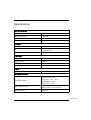
Specifications
3URGXFWGHVFULSWLRQ
Type of product
Digitizer
Commercial name
ADC Solo
Model number
5155
Original seller/manufacturer
Agfa-Gevaert NV-Mortsel
/DEHOOLQJ
CE
93/42 EEC ‘Medical Devices’ (Europe)
UL
UL 1950, CSA 22.2 No. 950
(North America)
CUL
(North America)
'LPHQVLRQV
Length, at cassette slot
730 mm
Length, at foot
700 mm
Width
450 mm
Height
1408 mm
:HLJKW
Unpacked
215 kg
(OHFWULFDOFRQQHFWLRQ
Europe: 230 V ± 10%
Operating voltage
USA: 120 V + 6%, -10%
Japan: 100 V ± 10%
208 V + 6%, -10%,
Mains fuse protection
Mains frequency
40
Europe: 16 A, slow blow
USA & Japan: 15 A, slow blow
50/60 Hz
2301A GB 19990507
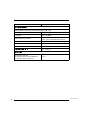
3RZHUFRQVXPSWLRQ
Standby
• 230 V/ 50 Hz configuration
230 W
• 208 V/ 60 Hz configuration
227 W
• USA: 120 V/ 60 Hz configuration
216 W
• Japan: 100 V/ 60 Hz
220 W
During operation
• 230 V/ 50 Hz configuration
max. 1610 W
• 208 V/ 60 Hz configuration
max. 1470 W
• 120 V/ 60 Hz configuration (USA)
max. 1440 W
• 100 V/ 60 Hz (Japan)
max. 1500 W
(QY LURQPHQWDOUHTXLUHPHQWV
Room temperature
15 °C - 30 °C
Maximum temperature change
0.5 °C/min.
Relative humidity
10 % - 75 %
Magnetic field (Dynamic)
compliant with EN 61000-4-8, Level 5
Sunlight exposure
not be operated in full sunlight
:DUPLQJXSWLPH
2301A GB 19990507
• Cold start
fully operational after max. 30 min.
• Warm start
fully operational after self-test
if not switched off for more than 3 min.,
after 30 min. operation
&DVVHWWHIRUPDW
FRUUHVSRQGLQJ,3IRUPDW
24 x 18 cm
238 x 178 mm
30 x 24 cm
298 x 238 mm
35 x 35 cm
354 x 354 mm
35 x 43 cm
354 x 430 mm
30 x 15 cm
298 x 148 mm
12 x 10”
303 x 252 mm
41
10 x 8”
252 x 201 mm
3K\VLFDOHPLVVLRQV
Noise emission (sound power level according to ISO 7779)
• During scanning
max. 65 dB(A)
• Standby
max. 45 dB(A)
Radio frequency emission
according to EN 55022:1997, Class B and
FCC, Part 15, Subchapter B, Class A
Heat emission
• During scanning
max. 1610 W
• Standby
230 W
&DVVHWWHUHWXUQWLPH
60 - 72 secs
(QGRI/LIH
Estimated product life
(if regularly serviced and maintained
according to Agfa instructions)
42
7 yrs.
2301A GB 19990507
2301A GB 19990507
43
Printed in Belgium
Published by Agfa-Gevaert N.V., B-2640 Mortsel-Belgium
2301A GB 19990507