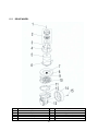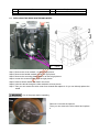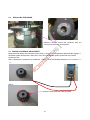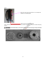
1
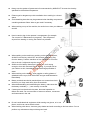
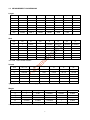
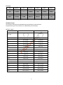
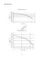
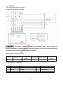
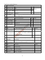
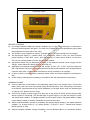
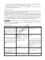
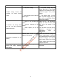
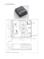
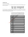
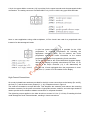
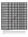
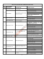
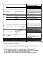
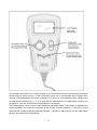
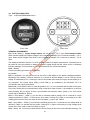
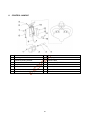
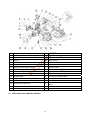
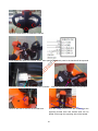
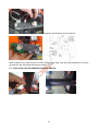
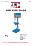
NOBLELIFT EQUIPMENT Service & Maintenance Manual LPT22 Power Pallet Truck V-LPT22-01.00 Date: 2011-02-26 CONTENTS FOREWORD ............................................................................................................................................2 1. GENERAL.........................................................................................................................................3 1.1 INTRODUCTION – MAINTENANCE SAFETY PRECAUTIONS..............................................3 1.2 MEASUREMENT CONVERSIONS ..........................................................................................7 2. SPECIFICATION.............................................................................................................................11 2.1 LOCATION OF COMPONENTS ............................................................................................11 2.2 SPECIFICATION SHEETS.....................................................................................................12 2.3 LUBRICATION.......................................................................................................................13 3. ELECTRICAL SYSTEM..................................................................................................................14 3.1 ELECTRICAL DIAGRAM.......................................................................................................14 3.2 INSTALLATION OF ELECTRIC.............................................................................................17 3.3 DRIVE WHEEL.......................................................................................................................19 3.4 POWER UNIT.........................................................................................................................19 3.5 BATTERY...............................................................................................................................19 3.6 CHARGER .............................................................................................................................24 3.7 CURTIS CONTROLLER ........................................................................................................29 3.8 BATTERY INDICATOR..........................................................................................................36 3.9 REPLACING THE ELECTRIC PARTS ..................................................................................38 3.10 TOOL FOR REPAIRING THE PIN OF ELECTRICAL PLUG .................................................43 4. HYDRAULIC SYSTEM ....................................................................................................................44 4.1 HYDRAULIC FLOW DIAGRAM .........................................................................................44 4.2 INSTALLATION OF HYDRAULIC SYSTEM........................................................................44 4.3 REPLACING THE POWER UNIT ........................................................................................45 4.4 REPLACING THE CYLINDER .............................................................................................46 4.5 CLEANING OIL TANK AND FILTER...................................................................................47 4.6 TROUBLE DIAGNOSTICS ..................................................................................................48 5. DRIVE WHEEL................................................................................................................................50 5.1 REPLACING THE DRIVE SYSTEM AND WHEEL ..............................................................51 5.2 REPLACING THE CARBON BRUSH KIT ...........................................................................52 5.3 REPLACING THE BRAKE...................................................................................................52 5.4 THE BRAKE CLEARANCE ADJUSTMENT........................................................................52 6. CONTROL HANDLE.......................................................................................................................54 6.1 REPLACING THE CONTROL HANDLE................................................................................55 6.2 REPLACING THE AIR SPRING AND MICRO SWITCH........................................................57 7. CASTER WHEEL............................................................................................................................58 7.1 REPLACING OF THE CASTER WHEEL...............................................................................58 7.2 ADJUSTING THE PRESSURE FOR THE DRIVE WHEEL ...................................................58 8. TROUBLE DIAGNOSTICS .............................................................................................................59 8.1 MAINTENANCE LIST ............................................................................................................59 8.2 TROUBLE SHOOT.................................................................................................................60 1 FOREWORD Proper operation, maintenance, troubleshooting and repairs are necessary to preserve the performance of the pallet truck over along period of time and ensure that fault and breakdowns do not occur. The object of this service manual is to provide the information necessary especially in connection with the performance of inspections and repairs mainly in the maintenance areas. The majority of this pallet truck consists of steel, it can be completely recycled. Waste material in conjunction with repairs, maintenance, cleaning or scrapping, must be collected and disposed of in an environment-friendly way and in accordance with the directives of respective countries. Such work must be carried out in areas intended for this purpose. Recyclable material should be taken care of by specialized authorities. Environmentally hazardous waste, such as oil filters, batteries and electronics, will have a negative effect on the environment, or health, if handled incorrectly. All of the information reported herein is based on data available at the moment of printing. Our products are constantly being developed and renewed, we reserves the right to modify our own products at any moment without prior notice and incurring in any sanction. So, it is suggested to always verify possible updates. 2 1. GENERAL 1.1 INTRODUCTION – MAINTENANCE SAFETY PRECAUTIONS Careless performing of the easy work may cause injuries. Take care to always perform work safely, at least observing the following. It is of utmost importance that maintenance personnel pay strict attention to these warnings and precautions to avoid possible injury to themselves or others, or damage to the equipment. A maintenance program must be followed to ensure that the machine is safe to operate. The specific precautions to be observed during maintenance are inserted at the appropriate point in the manual. These precautions are those that apply when servicing hydraulic and larger machine component parts. MODIFICATION OF THE MACHINE WITHOUT CERTIFICATION BY A RESPONSIBLE AUTHORITY THAT THE MACHINE IS AT LEAST AS SAFE AS ORIGINALLY MANUFACTURED, IS A SAFETY VIOLATION. SINCE THE MACHINE MANUFACTURER HAS NO DIRECT CONTROL OVER THE FIELD INSPECTION AND MAINTENANCE, SAFETY IN THIS AREA RESPONSIBILITY OF THE OWNER OR OPERATOR. FAILURE TO COMPLY WITH SAFETY PRECAUTIONS LlSTED IN THIS SECTION MAY RESULT IN MACHINE DAMAGE, PERSONNEL INJURY OR DEATH AND IS A SAFETY VIOLATION. When carrying out any operation or maintenance, have trained and experienced personnel carry out the work. When carrying out any operation or maintenance, carefully read out Operation and Maintenance Manual. Read all the precautions given on the decals which are fixed to the machine. Be sure you fully understand the contents of the operation. It is important to prepare necessary tools and parts and to keep the machine. Your safety, and that of others , is the first consideration when engaging in the maintenance of equipment. Always be conscious of weight. Never attempt to move heavy parts without the aid of a mechanical device. Do not allow heavy objects to rest in an unstable position. When raising a portion of the equipment, ensure that adequate support is provided. 3 It should be noted that the machines hydraulic systems operate at extremely high potentially dangerous pressures. Every effort should be made to relieve any system pressure prior to disconnecting or removing any portion of the system. Relieve system pressure by cycling the applicable control lowering button several times with the motor stopped and ignition on, to direct any line pressure back into the reservoir. Pressure feed lines to system components can then be disconnected with minimal fluid loss. Remove all rings, watches and jewelery when performing any maintenance. Wear well-fitting helmet, safety shoes and working Clothes When drilling grinding or hammering always. Wear protective goggles. Always do up safety clothes properly so that they do. Not catch on protruding parts of machines. Do not wear oily clothes. When checking, always release battery plug. DO NOT WEAR LONG HAIR UNRESTRAINED, OR LOOSE-FITTING CLOTHING AND NECKTIES WHICH ARE APT TO BECOME CAUGHT ON OR ENTANGLED IN EQUIPMENT. During maintenance do not allow any unauthorized person, to stand near the machine. Flames should never be used instead of lamps. Never use a buring flame to check leaks or the level of oil or electrolyte. Immediately remove any oil or grease on the floor of the operator’s compartment or on the handrail. It is very dangerous if someone slips while on the machine. Always use the recommended pure oil or grease, and be sure to use clean containers. Oil is a dangerous substance. Never handle oil, grease or oily clothes in places where there is any fire or flame. As preparation for use of fire extinguishers and other fire- fighting equipment. Keep the battery away from fire hazards. The generated gases are explosive. Store all the oils in a specified place. Keep the flammable things away from the machine. Do not smoke in the working site. Battery should always be disconnected during replacement of electrical components. 4 Always use the grades of grease and oil recommended by NOBLELIFT choose the viscosity specified for the ambient temperature. Exhaust gas is dangerous provide ventilation when working in a closed space. Avoid breathing dust that may be generated when handling components containing asbestos fibers. Wear a gas mask if necessary. When working on top of the machine, be careful not to lose your balance and fall. Hand a caution sign in the operator’s compartment (for example “Do not start” of “Maintenance in progress”). This will prevent anyone from starting or moving the machine by mistake. When welding on the machine or working on the electical system, ALWAYS turn the key switch OFF and remove the battery plug from the battery. Park the machine on firm, flat ground. Lower the fork to the min. height and stop the motor. Sulfuric acid in battery electrolyte is poisonous. Ist is strong enough to burn skin and eat holes in clothing. If you spill acid on your clothes or skin, immediately flush it with large quantities of water. When working on the battery, wear goggles or safety glasses. If splashed into the eyes, flush with water and get medical attention immediately. Battery terminals touched by metal objects can cause short circuit and burn you. Keep tools away from the terminals. When disassembling and assembling the battery, make sure that the battery terminals (+, –) are correctly connected. If water gets into the electrical system, abnormal operation or failure can result. Do not use water or steam on sensors, connectors and instruments in the cab. Do not handle electrical equipment while wearing wet gloves, or in wet places, as this can cause electric shock. When working with others, choose a group leader and work according to his instructions. Do not perform any maintenance beyond the agreed work. 5 Unless you have special instructions to the contrary, maintenance should always be carried out with the motor stopped. If maintenance is carried out with the motor running, there must be two men present : one operating the pallet truck and the other one performing the maintenance. In such a case, never touch any moving part. Before making adjustment, lubricating or performing any other maintenance, shut off all power controls. When removing parts containing O-ring Gaskets or seal. Make sure clean the mounting surface and replace with new sealing parts. Thoroughly clean the machine. In particular, be careful to clean the grease fittings and the area around the dipsticks. Be careful not to let any dirt or dust into the system. Use only approved, nonflammable cleaning solvents. When changing the oil or fitter, check the drained oil and filter for any signs of excessive metal particles or other foreign materials. Always use NOBLELIFT genuine parts for replacement. ENSURE REPLACEMENT PARTS OR COMPONENTS ARE IDENTICAL OR EQUIVALENT TO ORIGINAL PARTS OR COMPONENTS. When checking an open gear case, there is a risk of dripping things in. Before removing the covers to inspect such cases, empty everything from your pockets. Be particularly careful to remove wrenches and nuts. 6 1.2 MEASUREMENT CONVERSIONS Length Unit cm m km in ft yd mile cm 1 0.01 0.00001 0.3937 0.03281 0.01094 0.000006 m 100 1 0.001 39.37 3.2808 1.0936 0.00062 km 100000 1000 1 39370.7 3280.8 1093.6 0.62137 in 2.54 0.0254 0.000025 1 0.08333 0.02777 0.000015 ft 30.48 0.3048 0.000304 12 1 0.3333 0.000189 yd 91.44 0.9144 0.000914 36 3 1 0.000568 mile 160930 1609.3 1.6093 63360 5280 1760 1 1mm=0.1cm, 1m=0.001mm Area Unit cm2 m2 km2 a ft2 yd2 in2 cm2 1 0.0001 – 0.000001 0.001076 0.000012 0.155000 m2 10000 1 0.000001 0.01 10.764 1.1958 1550.000 km2 – 1000000 1 10000 1076400 1195800 – a 0.01 100 0.0001 1 1076.4 119.58 – ft2 – 0.092903 – 0.000929 1 0.1111 144.000 yd2 – 0.83613 – 0.008361 9 1 1296.00 in2 6.4516 0.000645 – – 0.006943 0.000771 1 1ha=100a, 1mile2=259ha=2.59km2 Volume Unit cm3 = cc m3 l in3 ft3 yd3 cm3 = m l 1 0.000001 0.001 0.061024 0.000035 0.000001 m3 1000000 1 1000 61024 35.315 1.30796 l 1000 0.001 1 61.024 0.035315 0.001308 in3 16.387 0.000016 0.01638 1 0.000578 0.000021 ft3 28316.8 0.028317 28.317 1728 1 0.03704 yd3 764529.8 0.76453 764.53 46656 27 1 1gal(US)=3785.41 cm3=231 in3=0.83267gal(US) Weight Unit g kg t oz lb g 1 0.001 0.000001 0.03527 0.0022 kg 1000 1 0.001 35.273 2.20459 t 1000000 1000 1 35273 2204.59 oz 28.3495 0.02835 0.000028 1 0.0625 lb 453.592 0.45359 0.000454 16 1 1 tonne(metric)=1.1023 ton(US)=0.9842 ton(UK) 7 Pressure Unit kgf/cm2 bar Pa=N/m2 kPa lbf/in2 lbf/ft2 kgf/cm2 1 0.98067 98066.5 98.0665 14.2233 2048.16 bar 1.01972 1 100000 100 14.5037 2088.6 Pa=N/m2 0.00001 0.00001 1 0.001 0.00015 0.02086 kPa 0.01020 0.01 1000 1 0.14504 20.886 lbf/in2 0.07032 0.0689 6894.76 6.89476 1 144 lbf/ft2 0.00047 0.00047 47.88028 0.04788 0.00694 1 kgf/cm2=735.56 Torr(mmHg)=0.96784atm Standard torque The following charts give the standard torque specification of bolts and nuts. Exceptions are given in the sections of “Disassembly and Assembly” METER TABLE Classification 4T, 5T 10T 10.9 Bolt type Bolt size Torque kgf · m (lbf · ft) Torque kgf · m (lbf · ft) M4 0.2 ± 0.02 0.4 ± 0.04 M5 0.3 ± 0.03 0.8 ± 0.08 M6 0.5 ± 0.05 1.4 ± 0.14 M8 1.2 ± 0.12 3.3 ± 0.3 M10 2.3 ± 0.23 6.5 ± 0.7 M12 4.0 ± 0.4 11.3 ± 1.1 M14 6.4 ± 0.6 17.9 ± 1.8 M16 9.5 ± 0.9 26.7 ± 2.7 M18 13.5 ± 1.4 38.0 ± 3.8 M20 18.6 ± 1.9 52.2 ± 5.2 M22 24.7 ± 2.5 69.4 ± 6.9 M24 32.1 ± 3.2 90.2 ± 9.0 M30 62.6 ± 6.3 176.1 ± 17.6 M36 108.2 ± 10.8 304.3 ± 30.4 M42 171.8 ± 17.2 483.2 ± 48.3 M45 211.3 ± 21.1 594.3 ± 50.4 8 INCH TABLE 4T, 5T 10T Bolt size Torque kgf · m (lbf · ft) Torque kgf · m (lbf · ft) 1/4 0.6 ± 0.06 1.7 ± 0.2 5/16 1.2 ± 0.12 3.0 ± 0.3 3/8 2.0 ± 0.20 5.6 ± 0.5 7/16 3.2 ± 0.32 8.9 ± 0.9 1/2 4.7 ± 0.47 13.4 ± 1.3 9/16 6.8 ± 0.68 19.0 ± 1.9 5/8 9.3 ± 0.93 26.1 ± 2.6 3/4 16.0 ± 1.60 45.1 ± 4.5 7/8 25.5 ± 2.55 71.6 ± 7.2 1 38.0 ± 3.80 106.9 ± 10.7 1-1/8 54.1 ± 5.41 152.2 ± 15.2 1-1/4 74.2 ± 7.42 208.9 ± 20.9 1-3/4 98.8 ± 9.88 277.8 ± 27.8 1-1/2 128.2 ± 12.82 360.7 ± 36.1 Classification Bolt type The torque specifications in above table shall not be applied to the bolts with nylon packings and nonferrous metal washers, or the ones with specifically designated torque and standard. H Newton meter : 1 N·m = 0.1kgf·m TIGHTENING TORQUE OF SPLIT FLANGE BOLTS The following torque shall be applied to the split flange bolts. Diameter Flat width (mm) (mm) kgf·m Torque N·m 10 14 6.7 ± 0.7 66.7 ± 6.8 12 17 11.5 ± 1 112 ± 9.8 16 22 28.5 ± 3 279 ± 29 9 APPROXIMATE CONVERSIONS SI Unit Conv Factor 0.113 1.36 7.22 × × × × × × × × × × × × × × 0.249 3.38 6.89 0.069 0.070 0.069 0.00689 = kPa = kPa = kPa = bar* = k f/ 2* = bar* = MPa × × × × Power r (W = J/s) 1.36 = PS (cv) 1.34 = HP 0.948 = Btu/s 0.74 = ft·lb/s × × × × 0.736 0.746 1.055 1.36 = = = = kW kW kW W × 1.055 × 4.19 = = kJ J kilopascal (kPa) kilopascal (kPa) kilopascal (kPa) (bar) (kg/cm2) newton/mm2 megapascal (MPa) (Pa=N·m2) Energy (J = N·m) × 0.948 = Btu × 0.239 = calorie kilojoule (kJ) joule (J) (J=N·m) SI Unit × × × × × × 8.9 0.74 0.102 Conv Factor = ln·in = lb·ft. = kg·m Pressure (Pa = N/m2) 4.0 = in. H2O 0.30 = in. Hg 0.145 = psi 14.5 = psi 14.22 = psi 145.04 = psi 145 = psi newton meter (N·m) newton meter (N·m) newton meter (N·m) kilowatt (kW) kilowatt (kW) kilowatt (kW) watt (W) (W=J/s) Non–SI Unit Torque = = = Velocity and Acceleration ×3.28 × 0.305 meter per sec (m/s ) = ft/s2 = × 3.28 × 0.305 meter per sec (m/s) = ft/s = × 1.61 kilometer per hour (km/h) × 0.62 = mph = Horse Power/Torque BHP × 5252 R.P.M. = TQ (lb·ft) TQ Z R.P.M. 5252 = B.H.P. Temperature °C = (°F–32) ÷ 1.8 °F= (°C Z 1.8) + 32 Flow Rate 3 × 0.264 liter/min (dm /min) = US gal/minZ3.785 = Note : ( ) Non–SI Unit 2 2 10 N·m N·m lb·ft.* m/s2 m/s km/h l/min 2. SPECIFICATIONS 2.1 LOCATION OF COMPONENTS 1. Control Handle 2. Key Switch (ON/ OFF) 3. Emergency Stop Button Or Kill Switch 4. Battery Indicator CURTIS 803 5. Controller assembly 6. Foot Pedal CONTROL HANDLE 7. 8. 9. 10. 11. 12. Drive Wheel (Inside The Cover) Stabilizing Caster (Inside The Cover) Pump Unit (Inside The Cover) Lift Cylinder Battery (Inside The Cover) Load Roller 1. Raise/Lower buttons adjusting fork height. – Rocker 2. FWD/BWD/REV travel button variable speed by turning knob switches –Control 3. Emergency Reverse button – Emergency reverse button or commonly known as the belly button switch 4. Horn button 5. Indicator light – Indicates high/low speed status. Green indicates high speed, red indicates slow speed. 6. Shift button – Shift button for high speed and low speed 11 2.2 SPECIFICATION SHEETS Wheels types Weight Characteristics 1.2 1.3 Model of manufacture Power supply (electric, diesel, petrol, gas, mains Electric 1.4 Type of operation (hand, pedestrian, stand on, rider Pedestrian 1.5 Capacity / rated load Q KGs 1.6 Load center distance C mm 600 1.8 Load distance X mm 963/1033 1.9 Wheelbase Y mm 2.1 Weight (including battery) KGs 1368 512 KGs 1082/1630 KGs 399/113 Axle loadings laden 2.3 Axle loadings unloaded 3.1 Tyres (rubber, Vulkollan, pneumatic, polyurethane) 3.2 Tyre size Dia. x width drive end mm Φ230x75 3.3 Tyre size Dia. x width load end mm 2 xΦ84x70/Φ84x93 3.4 Castor wheels (dimensions) Wheels, number(x=drive wheel) 3.5 drive end / load end Dimensions Performance Electric motor 2200 2.2 drive end / load end Polyurethane mm 2xΦ100x40 1x -2/ 2/ 1x -2/ 4 3.6 Track width (front) drive end b10 mm 500 3.7 Track width (rear) load end b11 mm 380/525 4.4 Lift height h3 mm 120 4.9 Tiller height in neutrality position h14 mm 1323 h13 mm 85 4.19 Overall length l1 mm 1815/1885 4.20 Length to front face of fork l2 mm 665 4.21 Overall width b1 mm s/e/l mm 726 60/160/1150(1220) 4.25 Overall fork width b5 mm 540/685 4.32 Floor clearance, center of wheelbase 4.34 Working aisle with 800x1200 pallet lengthwise m2 mm 25 Ast mm 2305/2344 4.35 turning radius Wa mm 1640/1710 4.15 Fork height lowered Other LPT22 4.22 Fork dimensions 5.1 Travel Speed laden / unloaded mph 5.2 / 5.5 5.2 Lifting speed laden / unloaded mm/s 19 / 35 5.3 Lowering speed laden / unloaded mm/s 30 / 27 5.8 Gradeability laden / unloaded % 5.10 Brakes 9/15 Electric-magnetic 6.1 Drive motor kw 1.5(AC) 6.2 Lifting motor kw 0.8 6.4 Battery voltage, normal capacity K5 V/Ah 24/210 6.5 Battery weight +/-5% KGs 185 6.6 Battery dimensions l /w / h mm 645/196/570 8.1 Type of drive control 8.4 Sound level at driver’s ears MOSFET Control Turning angle 12 dB(A) <70 ° 180 2.3 LUBRICATION Hydraulic oil Hydraulic oil must have anti-wear qualities at least. It is not advisable to mix oils of different brands or types, as they may not contain the same required additives or be of comparable viscosities. Name: Thickened hydraulic oil. ISO Viscosity Grade Characteristics At 40OC Viscosity At 50OC Viscosity index Flash point, Cleveland open cup Pour point, Max Density at 15 OC Copper corrosion(100OC, 3h) Foaming (93.5 OC) Vickers vane pump test, loss of mass (on vanes after 100h) Diameter of wear spot, 1200 r/min, 294N, 30min, 75 OC The oil for gear box Name: Extreme pressure lithium-based grease, 1#. Characteristics Worked Penetration, 0.1mm Dropping point, Extreme pressure (Timken OK) Similar viscosity (-10 OC, 10s-1) Corrosion preventive properties (52 OC, 48h) Wire points oil (100 OC, 24h) 13 #40 #30 57 40 ≥150 ≥160 ≤-35 48 30 ≥150 ≥160 ≤-35 861.5 ≤1 ≤30/0 15.3 ≤0.5 unit mm2/s O C C kg/m3 degree ml / ml mg mm O ≤1 ≤30/0 ≤100 ≤0.5 unit O C N Pa.s Grade % 310--340 ≥170 ≥177 ≤250 1 ≤10 3. ELECTRICAL SYSTEM 3.1 ELECTRICAL DIAGRAM WIRING DIAGRAM 14 CONNECTION DIAGRAM 15 No. Code NL. Drawing No. 1 GB CS1232.6.1 2 FU01 DQ-38 3 Mp WG-19-1 4 KMp WG-19-2 5 YV WG-19-3 6 Mt WG-54-1 7 YB WG-55-1 8 KM DQ-3 9 Kr DQ-2-1 10 FU02 DQ-17 11 Et DQ-19 12 VD DQ-10 13 FU1 DQ-9 14 S DQ-48 15 SY DQ-26-1 16 P DQ-27 17 B WG-5 18 SA, SU DQ-23 19 K DQ-14 20 HA DQ-22 21 VD DQ-10 22 F DQ-34-2 Master cable system drawing Serial 1 2 3 4 Part No 102043301 102043301 102043301 102043301 Description Battery – 24V/210Ah Fuse, 80A Motor for pump, DC24V/0.8kw Relay for motor of pump, DC24V Lower magnet valve, DC24V Motor for traction, DC16V/1.3kw Brake, DC24V Main relay C100/120 DC24V Thermal protection BD-W135/110 Fuse, 150A Controller CURTIS 1243C-2405 Diodes 1N5408 Fuse,10A Emergency button ZDK31-250 Lock LKS-101A Battery Indicator CURTIS 803 Control handle (94300-00) Micro switch Z-15GW2 Relay ARL2F DC24V Horn DC24V Diodes 1N5408 Discharger protection, PC802 NL. Drawing No. DQ-LPT22-X1 DQ-LPT22-X2 DQ-LPT22-X3 DQ-LPT22-X4 Description Drive motor cable Pump motor cable Main contactor cable Controller power cable 16 Qty. 1 1 1 1 1 1 1 1 1 1 1 1 1 1 1 1 1 1 1 1 1 1 Quantity 1 1 1 1 CANBUS handle cable drawing Serial No Part No NL. Drawing No. Description Quantity 1 1020433019 DQ-LPT22-X6 Controller cable 1 17 3.2 INSTALLATION OF ELECTRIC 1. Micro switch 10. Washer Φ8 19. Elastic washer 6 2. Screw 11. Horn 125 24V 20. Washer Φ6 3. Key switch 12. Locking nut M8 21. Screw 4. Emergency button 13. Screw M10X25 22. Plug 5. Battery indicator 803 14. Elastic washer 10 23. Charger 24V/30A 6. Screw M4×25 15. Nut M10 24. Battery 7. Washer Φ4 16. Cable clip 25. Socket 8. Locking nut M4 17. screw M6X30 9. Screw M8X25 18. Screw M6X16 M4×20 18 M6×30 3.3 DRIVE WHEEL Type: 3EL-DC-0.75 Drive Motor Model YDQ1.3-4BT Rate voltage 16V AC R.P.M 3200rpm Rate output 1.3kw Rate hour 60min. Rated current 76.2A Amperager rating- max 110.7HZ Amperager rating- min H class Insulation class YDQ1.3-4BT Electromagnetic Brake Model G072-REB0510(20)P-R Rate voltage DC 24V Rate Power 30W Output Torque 16N·M transmission ratio i=1:30 Gear Box 3.4 PUMP UNIT Type: MR2-B-V1B-F4.5-PCMAV1Y-TK05C-F2 3.5 Item Specification Rated voltage 24V Rated output 0.8 kw R.P.M 2500 rpm Rated current 60 A Rated hour 1.8 min. Insulation class IP Code F class Displacement 0.7cc/rec Max. operating pressure 250bar IP54 BATTERY Rate Specification Rated voltage 24V Capacity (5 hours) 210Ah Overall size (L*W*H) 677mm*196mm*555mm Initial charge When the battery is charged for the first time, you should prepare the exclusive sulfuric acid and excluslve water of lead acids (lf no excusive water is present in local areas, distilled water can be 19 used). Slowly pour sulphuric acid into a container containing exclusive water(or distilled water), and churn it up with an acid-resistant stick. Keep it still until the fluid temperature drops to 35oC, then it can be poured into cells. The concentration of confected electrolyte is 1.280+0.005 (25 0C ). The conversion forrnula of electrolyte is: S25=St+0.0007*(t - 25) which: S25: The concentration of electrolyte in standard temperature of 25oC St: The actually measured concentration of electrolyte. T: Actually measured temperature. When confecting electrolyte, avoid pouring water into concentrated sulphuric acid, for fear that sulphuric acid splashes and leads to physical injury. In addition, please wear protective appliance. Wipe up the cells, check the nuts be tight for reliable connection. Pour configured electrolyte into grouped batteries, with fluid level 15-20mm higher than protective slice. Keep it still for 4-6 hours (maximum duration no more than 12 hours). Only when the cells temperature drops below 350C can it be connercted to DC and charge. If cell’s temperature exceeds 35℃, it should be taken to cool it down. Check the cells in the battery for reverse polarity with DC voltmeter to assure proper polarity.Connect the anode of the power supply to “+ “of the battery, the cathode of the power supply to “-“ of the battery. Avoid reverse polarity for fear of reverse charging. The voltage of the charge power supply should be higher than 1.5 times of the charged battery. When all the work is properly done, the cells can be charged according to parameters outlined in the list below: Charging current (A) Model initial charge common charge Phase 1 (0.5 I5A) Phase 2 (0.25 I5A) Phase 3 (0.7I5A) Phase 4 (0.35 I5A) 210Ah 21 10.5 29 14.5 280Ah 28 14 39 19 350Ah 35 17 49 24 Initial charges are conducted in 2 phases: in phase1, when terminal voltages of the cells rise to 2.4V, the current should be converted into phase2, and continue to charge until air bubbles come out from the electrolyte, keep cell voltage(under constant current) steady for 3 hours. When the concentration of confected electrolyte reaches 1.280 士 0.005, it should remain unchanged within 3 hours. At this moment, the total quantity of electric charge should be 4-5 times the rated capacity, and the charging duration will be 70 hours. If the concentration of the electrolyte is not 1.280 士 0.005, it should be adjusted. The method is: if the concentration is too high, draw out some electrolyte and add some water or distilled water, until the concentration equals to the prescribed value; if the concentration is too low, draw out some electrolyte and add some pre-confected dilute sulfuric acid with a concentration of 1.400g/cm3, until the concentration equals to the prescribed value. When the concentration of electrolyte is adjusted, it should be charged for 1 hour for consistency. The density-ratio of electrolyte is as follows: Concentration of electrolyte 1.100 1.200 1.270 1.280 1.400 Volumeratio of water to sulfuric acid 9.80:1 4.33:1 2.80:1 2.75:1 1.90:1 20 Capacity ratio of water to sulfuric acid 5.84:1 2.36:1 1.57:1 1.49:1 1.00:1 After charging, close the vent plug , and it only can be put into use after its surface is cleaned clear. Balanced charge When in use, nonuniformity of voltage capacity, electrolyte and concentration may occur. Through balanced charge, such nonuniformity can be eliminated, and all cells in the battery can be of uniform conditions. Balanced charge is essential monthly for the batteries in use or following situation: Cells whose discharge voltages are usually below the final voltage (1.7V/cell). Cells with heavy discharge current (in circumstances where the drive motor and lift motor operate synchronously with heavy load), or in circumstance with steep slope. Cells not timely recharged after discharged. Undercharged cells of cells not used for along time. METHODS OF BALANCED CHARGE: Normally charge the cells, when it is fully charged, shut off the charge power supply, keep it still for half an hour, then switch on the power supply and continue to charge with the current of phase 2. When air bubbles come out, convert to 1/2 of the current of phase 2 and continue to charge the cells, when air bubbles are produced, shut off the charge power supply, keep is still for half an hour, then switch on the power supply and continue to charge with 1/2 of the current of phase 2, until air bubbles are produced, stop charging and left it still. Repeat the procedure for several times, until air bubbles are produced as soon as power supply is connected. In balanced charge, voltage of each cell as well as the electrolyte concentration should be measured and recorded. Before the charge is completed, the electrolyte concentration and height should be adjusted to the prescribed parameters. SULFURIC ACID FOR CELLS Index name Index Sulphuric acid (H2S04) % ≥92 Ignition residue % ≤0.03 Manganese (Mn) % ≤0.0005 Ferrum(Fe) % ≤0.005 Arsenic(As) % ≤0.00005 Chlorine(Cl) % ≤0.0005 Nitrogenoxides(calculatedby N) % ≤0.0001 Ammonia salt (NH4) % ≤0.001 Sulfur dioxide(S02) % ≤0.004 Copper (Cu) % ≤0.0005 Deoxidized potassium permanganate (0) % ≤0.001 Chorma ml ≤1.0 mm ≥160 Transparency WATER FOR LEAD ACID CELLS Index Index name % Appearance Mg / l Achromatic, transparent Residue content ≤ 0.01 100 Manganese (Mn) content ≤ 0.00001 0.1 Ferrum(Fe) content ≤ 0.0004 4 21 Chlorine(Cl) content ≤ 0.0005 5 Ammonia salt content ≤ 0.0003 3 Ammonia (NH4) content ≤ 0.0008 8 Deoxidized potassium permanganate (0) content ≤ 0.0002 2 Solonetz meatal oxide(CaO) content ≤ 0.005 0 Resustivity(25 C) Ω.cm 50 4 10x10 ≥ ELECTROLYTRE FOR LEAD ACID CELLS Index Index name % Appearance Mg / l Achromatic, transparent Sulphuric acid (H2S04) content 0 15~40 3 Concentration 50 C, g/cm 180~480 1.1~1.3 Ignition residue content ≤ 0.02 0.24 Manganese (Mn) content ≤ 0.00004 0.00048 Ferrum(Fe) content ≤ 0.004 0.048 Arsenic(As) content ≤ 0.00003 0.00036 Chlorine(Cl) content ≤ 0.0007 0.0084 Ammonia salt content (N) ≤ 0.0005 0.006 Copper (Cu) content ≤ 0.002 0.024 Deoxidized potassium permanganate content ≤ 0.0008 0.01 Content calculated by KMn04 ≤ 0.0032 0.038 Don't spatter electrolyte or water into the batteries otherwise the battery tank will be eroded and the battery will automatically discharge, which will lead to low performance of battery and even shorter life. If electrolyte or water are spattered into the unintentionally, please discharge with the exclusively equipped plastic pipes. 22 DISCHARGE CURVE voltage (V) 5hr discharge curve 2.1 2.05 2 1.95 1.9 1.85 1.8 1.75 1.7 1.65 1.6 0 1 2 3 4 5 6 time(h) voltage ( V) 0.5hr disvharge curve 2 1.95 1.9 1.85 1.8 1.75 1.7 1.65 1.6 1.55 1.5 1.45 1.4 0 5 10 15 20 time(min) 23 25 30 35 3.6 CHARGER Type: DF2430 (for 24V/210Ah battery) WIRING DIAGRAM FOR CHARGER The battery generates flammable and explosive gases during charge, so excellent ventilation is required. Open the liquid refilling cap or seal cap. Do not smoke around the battery during charge. Any fire and spark is forbidden. MAIN PRODUCT SPECIFICATION Type Input power Battery capacity Input voltage Output voltage Output current range DF2430 1.4KVA 200-220 220v 31.2 30A ENVIRONMENTAL CONDITION No. Item Technical specification 1 Humidity 5%-80% 2 Altitude ≦2000 3 Cooling Fan convection cooling Unit Remark With package m 24 Work normally Working under full load ELECTRICAL CHARACTERISTICS 1 Input characteristics No. Item Technical specification Unit 1.1 Rated input voltage 220 Vac 1.2 Input voltage range 209-231 Vac 50—60 Hz DF2430:7 A 1.3 AC input voltage frequency 1.4 Max input current 1.5 Fan function 2 Output characteristics No. Item Technical requirements Unit 2.1 Fast charge voltage 28.8 Vdc 2.2 Floating voltage 31.2 Vdc 2.3 Maintain voltage 28.8 Vdc 2.4 Constant current DF2430:30 A 2.5 Power efficiency 3 Protection characteristics No. Item 3.1 Output Remark 220Vac When input is on,voltage for fan,When input voltage is off,there is no output voltage for fan over voltage protection Remark ≥80% Technical requirements Unit 32 V Remark When the transformer temperature is higher than 3.2 Thermal protection 125 ℃ -130 ℃ , the charger automatically protect, stop charging. 3.3 3.4 3.5 Output current limiting protection DF2430:30 A Output short circuit If a short circuit load, the charger will be protected and protection will not work. Electronic reverse The battery protection permanent revers battery connection charger is electronically 4 Charger(LED) indicator No. Item Status LED 1 Power on Power LED on (Yellow) 2 Power off Power LED OFF 3 Fast Charge Full LED ON (RED) 4 Floating Charge Full LED ON (RED) 5 Full LED ON (GREEN) 6 Fault LED Charging Battery protected against Remark LED (RED) 25 DF2430 charger Equalizing charge Power switch BEFORE CHARGING The charger shall be installed in a special, ventilated, dry, no dust, no corrosive gas, no interference from high electromagnetic field place. The shell of the charger should be earthed (the ground bolts are equipped at the lower part of the case). The charger is only available for indoors, off-board charger. No water should be in the charger. The input power supply is 1- phases, 220V±5%~230V±5%, 50Hz or 110V±5%, 50Hz.The lead section shall be no less than 4 mm², while the capacity of mains switch shall be no less than 30A.You are recommended to use the dynamic mains switch. Appropriate cables may be employed according to the distance between power supply and the charger, which makes the voltage drop no more than 5%. Applicable environmental temperature for the charger is from -10℃ to 40℃ and the height less than 1000 meters. During use, the stumbling block that affects heat radiation of the charger shall be 0.6 meter away from it. Please check the blower is running normally or not regularly. In case of failure of microcomputer controller, please inform the service engineer or maintenance staff. Check height of electrolyte in the battery in accordance with the manufacturer’s instructions. COMMON CHARGE Connect cable plug of the battery to corresponding output plug of the charger firmly. Connect the battery firstly, then connect it to the power supply and finally start it. If the output plug is connected to the electric control terminal of the vehicle mistakenly, the charger fails to work, the indicator light for “failure” is on, please correct it timely. Connect the charger to power supply first, then turn on the power air switch and the charger starts after the power is connected. The indicator light for power supply is on and the charger is under self-examination condition. The display indicates current system version, chargeable battery voltage, current battery voltage, maximum chargeable current and other data. After the self-examination process is completed, the charger begins charging. The display indicates voltage[**.*V], charge current [**.*A], charge time[H**.**] (shows ** Hour, ** Minute) and charged electric quantity [***AH]. When the display indicates “Charge completion” and the indicator light is on, the battery finishes 26 charge. The charger enters floating charge, with current of 1-3 amperes. Please check electrolyte height in the battery frequently and fill distilled water timely as required. Disconnect the power switch, and disconnect the output cable plug of the charger and plug of battery and the charge is completed. EQUALIZING CHARGE When the battery group has been used for some time, the performance parameters of the batteries may vary differently, so equilibrium (constant current) charge is required. If equalizing charge is required, press the key for “Balance” charge, turn on the power switch, then the indicator light for “Balance” is on. The charger enters into equalizing charge status, the current value reduces from the rated value to a constant current value during charge, meanwhile, the display indicates “-FC-“. When the equalizing charge is completed, manual turning off is required (note: the output current of the charger under equalizing charge is constant without stop, manual turning off is necessary). Press the key for “Balance” charge after turning off the charger to make it return to normal charge. The equalizing charge is a manual operation. Appointed personnel are required to observe and check voltage and specific gravity of the batteries and determine charge time, manual power off and charge stop as required. TROUBLESHOOTING Failures Causes Troubleshooting The indicator light for power is on, the indicator light for failure is on, the blower is on, the charger can not start and charge and the monitor is not display . The battery is not connected, or the output plug of the charger is inserted into the controller plug of the electric vehicle. Connection of the battery should be corrected. ① Although the charger and battery is connected, however, some part of which is disconnected. ②The battery is aging, becomes invalid and low voltage. ① Check each connection bolt and wiring. The indicator light for power is on, the indicator light for failure is on, the blower is on, the charger can not start and charge and the monitor is not display . ③The battery oppositely. is connected The indicator light for power is on, the indicator light for failure is on, the blower is on, the charger can not start and charge and the display. Failure of Instable charge current, more or less. Long-term heating, poor contact or loose by the output plugs. DC output fuser. 27 ② Check total voltage of battery and each single voltage of the battery. In case of open circuit, aging, invalid, low voltage of the battery, please change a new one. ③ Correct the incorrect connection. Open the side door to check the fuser. If the fuser is broken, please change a new one. Check the copper plates, if it is unavailable, please change a new one. ① Low power voltage. Instable charge current, not reaching the rated current value. Air switch of the charger does not trip, and the preceding stage switch trips. ② Small section area of lead for power input. ① Failure of the preceding air switch. ② Incorrect matching of air switch. ③ Small capacity of the air switch. Rated current of the preceding stage air switch is more than that of the air switch of the charger. The air switch must be type D (dynamic type),type C (illumination type) is unavailable. Internal short circuit of single battery of the group. Check each terminal voltage of every single battery. If some of the voltages are lower than their nominal voltages, the internal polar plates suffers from short circuit, please remove them and change new ones. Failure of microcomputer control power. Please inform engineers. Excessive overcharge for the battery. The display signals of the display face rolling, deadlock and clobber. ① The power voltage may not lower than 95% of the rated voltage. If the voltage is too low, please change a new power supply. ② The section area of input lead of power supply may not less than the stipulated section area in the manual. 28 or the service 3.7 CURTIS CONTROLLER 29 CONNECTIONS Low Current Connections Three low current connectors (J1, J2, J3) are built into the 1230 controller. They are located in a row on the top of the controller: 4-pin 6-pin 24-pin J3 J2 J1 The 24-pin connector (J1) provides the logic control connections for the contactor drivers and switches that are wired directly to the vehicle. The mating connector is a 24-pin Molex Mini-Fit Jr. connector part number 39-01-2245 using type 5556 terminals. Pin 1 Keyswitch input(KSI) Pin 2 interlok Pin 3 Not used Pin 4 Not used Pin 5 Not used Pin 6 Not used Pin 7 Not used Pin 8 Not used Pin 9 Not used Pin 10 Not used Pin 11 CAN HI Pin 12 CAN Lo Pin 13 Mode switch input Pin 14 emergency reverse Pin 15 Not used Pin 16 Output 1(horn relay) Pin 17 Output 2 Pin 18 Output 3 Pin 19 Not used Pin 20 Not used Pin 21 Not used Pin 22 main contactor driver output Pin 23 Pwm output 1(lift contactor) Pin 24 Pwm output 2(lowering valve) 30 A 6-pin low power Molex connector (J2) is provided for the speed encoder and electromagnetic brake connections. The mating connector is a Molex Mini-FitJr. p/n 39-01-2065 using type 5556 terminals. Note: In some applications using a tiller multiplexer, J2 Pins 3 and 6 are used for a proportional valve instead of an electromagnetic brake. A 4-pin low power connector (J3) is provided for the 13XX programmer. A complete programmer kit, including the appropriate connecting cable, can be ordered; see Curtis programmer manual for further information on the various programmers available for programming Curtis controllers. J3 can also be used for the Curtis Model 840 Spyglass display. Although the display is typically wired directly into Pins 19, 20, and 21 of the 24-pin connector (J1), it can alternatively be plugged into J3 and unplugged when the programmer is used. Only Pins 2, 3, and 4 of J3 are needed for the display. High Current Connections Six round tin-plated brass studs are provided for the high current connections to the battery (B+ and B-), the fuse (F+), and the three motor phases (U, V, W), located as shown in Figure 2. The studs are threaded to accept M5 bolts. This simplifies the assembly and reduces the mounting hardware necessary for the power connections. Appropriate screws, washers, and cable lugs should be used to provide secure vibration-resistant connections on all power terminals. The tightening torque applied to the bolts should not exceed 10 N·m (7.4 ft-lbs). Exceeding this limit could damage the studs’ internal threads, resulting in loose connections. 31 Text Readaccess Writeaccess Unit Type Vehicle User Rates User M1 Accel Rate User User Seconds TI_UINT8 2 0.1 5 M2 Accel Rate User User Seconds TI_UINT8 2 0.1 5 M3 Accel Rate User User Seconds TI_UINT8 2 0.1 5 M4 Accel Rate User User Seconds TI_UINT8 2 0.1 5 M1 Decel Rate User User Seconds TI_UINT8 1.2 0.1 20 M2 Decel Rate User User Seconds TI_UINT8 1.2 0.1 20 M3 Decel Rate User User Seconds TI_UINT8 1.2 0.1 20 M4 Decel Rate User User Seconds TI_UINT8 1.2 0.1 20 M1 Brake Rate User User Seconds TI_UINT8 1 0.1 5 M2 Brake Rate User User Seconds TI_UINT8 1 0.1 5 M3 Brake Rate User User Seconds TI_UINT8 1 0.1 5 M4 Brake Rate User User Seconds TI_UINT8 1 0.1 5 Fast Stop Rate OEM OEM Seconds TI_UINT8 1 0.1 5 Accel Release Rate OEM OEM Seconds TI_UINT8 0 0 1 Speeds User M1 Min Speed User User % TI_UINT8 10 0 50 M2 Min Speed User User % TI_UINT8 10 0 50 M3 Min Speed User User % TI_UINT8 10 0 50 M4 Min Speed User User % TI_UINT8 10 0 50 M1 Forward Max Speed User User % TI_UINT8 50 10 100 M2 Forward Max Speed User User % TI_UINT8 100 10 100 M3 Forward Max Speed User User % TI_UINT8 50 10 100 M4 Forward Max Speed User User % TI_UINT8 50 10 100 M1 Reverse Max Speed User User % TI_UINT8 50 10 100 M2 Reverse Max Speed User User % TI_UINT8 100 10 100 M3 Reverse Max Speed User User % TI_UINT8 50 10 100 M4 Reverse Max Speed User User % TI_UINT8 50 10 100 Speed Limit Type OEM OEM TI_UINT8 0 0 1 Multi Mode User Anti Tiedown OEM OEM TI_ENUM8 0 0 1 Throttle User Throttle Deadband OEM OEM % TI_UINT8 10 0 30 Throttle Max User User % TI_UINT8 90 40 100 Throttle Map User User % TI_UINT8 50 5 90 Sequencing User Sequencing Delay OEM OEM Seconds TI_UINT8 0.2 0 3 SRO OEM OEM TI_UINT8 2 0 3 HPD OEM OEM TI_UINT8 1 0 2 OEM OEM TI_UINT8 1 0 1 OEM OEM TI_UINT8 60 0 60 Main Contactor Interlock e Main Contactor Open Delay Seconds 32 Value Min. Max. Main Contactor Check OEM OEM TI_ENUM8 0 0 1 Brake User Brake Fault Check OEM OEM TI_ENUM8 1 0 1 Brake Delay OEM OEM Seconds TI_UINT8 1 0 10 Brake Hold Voltage OEM OEM % TI_UINT8 100 0 100 Brake Driver Type OEM OEM TI_UINT8 0 0 2 Anti Rollback Time OEM OEM ms TI_UINT16 100 0 1000 Emergency Reverse User Speed OEM OEM % TI_UINT8 70 10 100 Direction Interlock OEM OEM 0 0 1 Time Limit OEM OEM Seconds TI_UINT8 1.5 0 10 Accel Rate OEM OEM Seconds TI_UINT8 1 0.1 5 Motor User Min Motor Voltage OEM OEM Volt TI_UINT16 0.1 0 6 Nominal Motor Voltage OEM OEM Volt TI_UINT16 16 7 30 Nominal Motor Frequency OEM OEM Hz TI_UINT16 111 20 400 Max Motor Speed OEM OEM rpm TI_UINT16 3800 1000 10000 Current Limit OEM OEM Ampere TI_UINT16 190 100 250 Current Limit PGain OEM OEM % TI_UINT16 25 0 100 Current Limit IGain OEM OEM % TI_UINT16 10 0 100 Number of Motor Poles OEM OEM TI_UINT8 4 2 8 Encoder Pulses per Rev. OEM OEM TI_UINT8 64 32 128 Swap Encoder Direction OEM OEM TI_ENUM8 0 0 1 Failsafe Delay OEM OEM TI_UINT16 5 2 20 Control User P Gain OEM OEM TI_UINT16 0.1 0 1 I Gain OEM OEM TI_UINT16 0.1 0 1.5 Accel Slip OEM OEM Hz TI_UINT16 5 1 5 Regen Slip OEM OEM Hz TI_UINT16 4 1 5 Slip Boost OEM OEM TI_UINT8 1 0 10 Pull-Out Slip OEM OEM Hz TI_UINT16 10 3.5 50 Accel Slip Voltage OEM OEM Volt TI_UINT8 4 0 10 Accel Comp OEM OEM TI_UINT8 0.4 0 5 Regen Slip Voltage OEM OEM TI_UINT8 1 0 5 Regen Comp OEM OEM TI_UINT8 3 0 5 Regen Voltage Offset OEM OEM Volt TI_UINT8 0 0 5 System User Battery User Full Battery Voltage OEM OEM Volt TI_UINT16 2.04 1.71 2.08 Empty Battery Voltage OEM OEM Volt TI_UINT16 1.73 0.9 2.01 BDI Reset Battery Voltage OEM OEM Volt TI_UINT16 2.09 2.03 3 Low Voltage Level OEM OEM Volt TI_INT16 1.5 1.33 2 Hourmeter User Enable Total Service Hours OEM OEM TI_ENUM8 0 0 1 Enable Drive Service Hours OEM OEM TI_ENUM8 0 0 1 TI_ENUM8 Seconds Volt 33 Adjust Hours OEM OEM Set Total Hours OEM Set Drive Hours Hours TI_UINT32 0 0 999999 OEM TI_ENUM8 0 0 1 OEM OEM TI_ENUM8 0 0 1 Total Service Hours OEM OEM Hours TI_UINT16 5000 100 5000 Drive Service Hours OEM OEM Hours TI_UINT16 5000 100 5000 Total Disable Hours OEM OEM Hours TI_UINT16 10 0 500 Drive Disable Hours OEM OEM Hours TI_UINT16 10 0 500 Drive Disable Speed OEM OEM % TI_UINT8 20 0 100 Service Total Expired Service Service TI_ENUM8 0 0 1 Service Drive Expired Service Service TI_ENUM8 0 0 1 Nodes 2.0 User Module ID OEM OEM TI_UINT8 5 1 31 Master ID OEM OEM TI_UINT8 0 0 3 Bitrate OEM OEM TI_UINT8 0 0 2 Manufacturing Date OEM Factory TI_UINT16 0 0 65535 OEM Fingerprint OEM OEM TI_UINT16 0 0 65535 PDO-MISO COB OEM Development TI_UINT16 33157 0 65535 PDO-MISO Data Length OEM OEM TI_UINT8 8 0 8 PDO-MISO Index 1 OEM OEM TI_UINT16 8318 0 65535 PDO-MISO Index 2 OEM OEM TI_UINT16 8319 0 65535 PDO-MISO Index 3 OEM OEM TI_UINT16 8318 0 65535 PDO-MISO Index 4 OEM OEM TI_UINT16 8319 0 65535 PDO-MISO Index 5 OEM OEM TI_UINT16 8318 0 65535 PDO-MISO Index 6 OEM OEM TI_UINT16 8319 0 65535 PDO-MISO Index 7 OEM OEM TI_UINT16 8320 0 65535 PDO-MISO Index 8 OEM OEM TI_UINT16 8322 0 65535 PDO-MISO Event Control OEM OEM TI_UINT8 0 0 2 PDO-MOSI COB OEM Development TI_UINT16 517 0 65535 PDO-MOSI Data Length OEM OEM TI_UINT8 8 0 8 PDO-MOSI Index 1 OEM OEM TI_UINT16 8296 0 65535 PDO-MOSI Index 2 OEM OEM TI_UINT16 8297 0 65535 PDO-MOSI Index 3 OEM OEM TI_UINT16 8320 0 65535 PDO-MOSI Index 4 OEM OEM TI_UINT16 8324 0 65535 PDO-MOSI Index 5 OEM OEM TI_UINT16 8323 0 65535 PDO-MOSI Index 6 OEM OEM TI_UINT16 8321 0 65535 PDO-MOSI Index 7 OEM OEM TI_UINT16 8298 0 65535 PDO-MOSI Index 8 OEM OEM TI_UINT16 8299 0 65535 PDO-MOSI Event Control OEM OEM TI_UINT8 2 0 2 NOTE: for “standard parameter”, 1=on, 0=off TROUBLESHOOTING CHART A Status LED is built into the controller. It is visible through a window in the label on top of the controller. This Status LED displays fault codes when there is a problem with the controller or with the inputs to the controller. During normal operation, with no faults present, the Status LED flashes steadily on and off. If the controller detects a fault, a 2-digit fault identification code is flashed continuously until the fault is corrected. 34 CURTIS 1230 CONTROLLER TROUBLESHOOTING CHART LED CODE PROGRAMMER LCD DISPLAY Motor speed encoder EXPLANATION POSSIBLE CAUSE Motor speed encoder pulses are not correct. 1. Incorrect encoder wiring. 2. Controller defective. 1. Incorrect encoder wiring. 1, 2. Motor blocked. 2 Motor Failsafe Motor stalled, or motor turning faster than desired. 3. Insufficient braking torque. 4. Motor control P Gain and I Gain settings too low. 5. Failsafe delay too short. 1, Motor Overcurrent Motor phase overcurrent. Motor Output Fault Motor output protection feature has been triggered. 3 1. Incorrect motor wiring. 2. Controller defective. 1. Incorrect motor wiring. 2. Controller defective. 1. Improper sequence interlock,and direction inputs. of KSI, 2. Wrong SRO type selected. 1,4 Static Return To Off SRO sequencing error. 3. Misadjusted throttle pot. 4. Direction switch open. 5. Sequencing delay too short. 6. Wrong throttle type selected. 1. Throttle input wire shorted to B+. 2,1 Throttle Wiper High Throttle wiper voltage is too high. 2. Defective throttle pot. 3. Wrong throttle type selected. 4. Incorrect speed limit pot wiring. 2,2 EMR Wiring Open Emergency reverse wiring fault. 1. Emerg. Rev. wire or check wire broken. 1. Improper sequence of KSI, interlock, and throttle inputs. 2. Wrong HPD type selected. 2,3 High Pedal Disable HPD sequencing error. 3. Misadjusted throttle pot. 4. Interlock switch open. 5. Sequencing delay too short. 6. Wrong throttle type selected. 2,4 Throttle Wiper Low Throttle wiper voltage is too low. 1. Throttle input wire shorted to B-. 2. Defective throttle pot. 3. Wrong throttle type selected. 1. MUX card not plugged in. 3,1 Multiplexer Fault Tiller multiplexer error. 2. MUX not wired properly. 3. MUX card defective. 3,2 Main Contactor Missing or welded main contactor. 35 1. Main contactor coil open. 2. Main contactor missing. 3. Wire to main contactor missing. 4. Main contactor stuck closed. 5. Main contactor driver shorted. Precharge 1. Controller defective. Precharge fault. 2. Low battery voltage. 1. Brake coil open. 3,3 Brake Fault Brake wiring or driver fault. 2. Brake missing. 3. Wire to brake missing. 4. Brake driver shorted. 4,1 Service Total Disable Total disable timer has expired. 1. Expired total disable timer. Service Driver Disable Drive disable timer has expired. 1. Expired drive disable timer. Total maintenance timer has expired. 1. Expired total maintenance timer. Drive maintenance timer has expired. 1. Expired drive maintenance timer. Battery voltage is too high. 1. Battery voltage >overvoltage cutback limit. Service Total Expired Service Driver Expired Battery Overvoltage 2. Operation with charger attached. 4,2 Battery Undervoltage Battery voltage is too low. 1. Battery voltage <undervoltage cutback limit. 2. Corroded battery terminal. 3. Loose battery or controller terminal. 1. Temperature >85 C or <-25 C. 4,3 Temperature Cutback Controller heatsink is too hot or too cold. 2. Excessive load on vehicle. 3. Improper mounting of controller. 4. Operation in extreme environment. 1. Mode switch shorted to B+. 4,4 Anti Tiedown Mode switch activated at startup. 5,1 Hardware Failure Hardware failure. 1. Controller defective. 5,2 Software Failure Software failure. 1. Controller defective. 5,3 Parameters Corrupt Parameters corrupt. 1. Controller defective. 2. Mode switch “tied down” to select M2 permanently. CURTIS 1311 HANDHELD PROGRAMMER The Curtis 1311 handheld programmer provides programming, diagnostic, and test capabilities for the controller. The power for operating the programmer is supplied by the host controller via a 4-pin Molex connector. The programmer includes a 7-line alphanumeric LCD display, rockertype keys for navigating through the display and for modifying parameters (+/-), and three keys that can be used as bookmarks. The 1311 programmer is easy to use, with self-explanatory functions. After plugging in the programmer, wait a few seconds for it to boot up and gather information from the controller. For experimenting with settings, the programmer can be left plugged in while the vehicle is driven. 36 The bookmark keys allow you to quickly go back to up to three selected items without having to navigate back through the menu structure. To set a bookmark, press one of the bookmark keys for about three seconds, until the Bookmark Set screen is displayed. To jump to a set bookmark location, quickly press the appropriate bookmark key (1, 2, or 3). Note that the bookmarks are not permanently stored in the programmer. They are cleared when the programmer is unplugged. The bookmark keys can be used to make parameter adjustment easier. For example, in adjusting the throttle deadband, you might set a bookmark at the Throttle % readout [Monitor > THROTTLE %] and another at the Throttle Deadband parameter [Program > THROTTLE DB]; this way you can easily toggle between the readout and the parameter. 37 3.8 BATTERY INDICATOR Type: CURTIS 803RB2448BCJ3010 Front View Rear View TERMINAL ASSIGNMENT Pin 7 or 8 = Battery +. Single voltage models: Pin 8 to battery +; Pin 7, open. Dual voltage models: When vehicle voltage is the higher voltage of the 2 operating voltages, Pin 8 connects to battery +; Pin 7, open. When vehicle voltage is the lower of the 2 operating voltages, Pin 7 connects to battery +, Pin 8, open. The discharge indicator uses Pin 7 or 8 for its battery state-of-charge measurements. Connection are to be made as close as possible to battery to prevent voltage drops that will cause errors in discharge indicator readings. The connection is not to be switched by the vehicle’s keyswitch. Pin 5 = Battery – Connect to battery ground as close to battery as possible. Pin 2 = Keyswitch. The keyswitch turns on and off the LED display of the battery discharge indicator. Monitoring of the battery continues when Pin 2 is turned off and the display is not lit. The hour meter display is unaffected by Pin 2, although it cannot accumulate more time as long as the keyswitch pin is not energized. The control inputs HRM (+) and HRM (–) are enabled by the keyswitch. Pin 2 is connected to the vehicle’s keyswitch. Pins 1 & 6 = Hour Meter Control. In normal operation, Pin 1 or 6 is connected and the other is left open. Only one of these pins is connected when using normal hour meter function. It is possible to or the hour meter between the two inputs so that it accumulates the total time either system is on. Hour meter control logic is detailed in Table 2. Pin 6 = Hour Meter +. HRM (+) (for use with a switched positive voltage). Pin 6 connects to a high voltage as defined in Table 1. to activate the hour meter. Leaving Pin 6 open or connecting it to a low voltage gives control of the hour meter to the Hour Meter (–) input. See Table 2. Pin 1 = Hour Meter –. HRM (–) (for use with a switched ground). Pin 1 connects to a low voltage level as defined in Table 1 to activate the hour meter. Leaving Pin 1 openor connecting it to high voltage gives control of the hour meter to the Hour Meter (+) input. Pin 3 = Relay. Pin 3 connects in series with the lift coil circuit (or the circuit to be switched at empty). For 38 holding relay (J), Pin 3 must be electrically closer to battery + than Pin 4 Pin 4 = Relay. Pin 4 also connects in series with the circuit to be switched at empty. HOUR METER CONTROL LINES & IMPEDANCE SPECIFICATIONS Low Voltage (max.) Hight Voltage (min.) 5.0VDC 15.0VDC Min. Impedance HRM+ HRM- 80kΩ 20 kΩ HOUR METER CONTROL LOGIC Pin 1 (HRM-) Pin 6 (HRM+) Hour Meter Status High Low Off High Open Off Open Low Off Open Open Off Low High On Low Low On Low Open On High High On Open High On DISCHARGE ADJUSTMENTS The followed table lists the voltages per cell under load that correspond to an empty indication on the gauge (lockout point). Setting K L M N O P Q R S T U Volt/Cell at Empty 1.57 1.63 1.68 1.73* 1.78 1.82 1.84 1.86 1.89 1.91 1.93 NOTE: “*” – factory setting RESET TYPE/LEVEL (AFTER OR DURING RECHARGE) CTR = Charge Tracking Reset: If the gage is connected to the battery during recharge, the gage will track the battery charge level. OCR = Open Circuit Reset: If the gage is disconnected from the battery during recharge, the gage will retain the last indication. It will advance to full when reconnected only if the battery voltage is above the OCR level. For standard (“B”) reset, OCR = 2.09 VPC (VPC = volts per cell.) TROUBLESHOOTING Problem Possible Causes No display Terminals not connected or improper voltage Stays at FULL Instrument voltage does not match battery voltage, B+ connected to the wrong terminal Will not reset Instrument voltage does not match battery voltage, or battery not fully charged Resets w/o charging battery Not connected directly to battery terminals EMPTY too soon B+ connected to wrong terminal, or instrument voltage does not 39 match battery voltage, or terminals not directly connected to battery 3.9 REPLACING THE ELECTRICAL PARTS REPLACING THE BATTERY Step 1: Remove 2 screws (No.2), loosen nuts (No.4) and washers (No.3). Step 2: Remove the battery cover (No.1) Step 3: Separate the plugs (No. 6 and 7) Step 4: Use two lifting hook to hook the hole of the battery box. Then you can use a crane to take away the battery and replace it REPLACING THE CONTROLLER, BATTERY INDICATOR, ETC. Remove screws. Then remove the right cover and left cover. You will see the appearance as the following three pictures when you remove the cover: 40 REPLACING THE POWER UNIT Remove the relay cable. Remove the pipe. Remove 2 screws. Then you can remove the power unit and replace it. REPLACING THE BATTERY INDICATOR Remove two plastic nuts (under the mounting board), remove the “U” clamp, disconnect the 8 - pins plug. Then you can remove the battery indicator and replace it. REPLACINGTHE FUSE 41 Open the black cover of the fuse seat, then you can remove the fuse and replace it. REPLACING THE MAIN RELAY Remove cables Remove two screws Remove the cables. Then you can remove the main relay and replace it. REPLACING THE CONTROLLER Step2: Remove two screws A B Step1: Remove all cables Step2: Remove two screws. Step3: then you can remove the controller and replace it. When reconnecting the controller, be careful to check the tightness of the power connection nut, Be sure to check the terminal connections. Taking part A and B for example: part A: It includes anode terminal and cathode terminal, if you connect by mistake, the circuit will be short out and the controller will be damaged. Part B: there are three terminals marked U,V,W. If you connect by mistake, the drive motor polarity will be reversed and will be demage the unit. 42 REPLACING THE THERMAL PROTECTION When the temperature of the motor is more than 130OC, the module will give a signal to the controller, then driving speed will automatically change to low-speed mode. After the temperature reduces to 110OC, the unit will change back to nomal speed. If one line of the cable open circuit, the driving speed will remain slow. Remove the screw and the plug, then you can remove the module and replace it. REPLACING THE LOCK (KEY SWITCH) LKS-101A Remove four screws that fix the plate into vehcle frame Lift the mounting plate. Remove the nut of the key switch. remove the cable of the key switch. 43 Then you can remove the key switch and replace it. REPLACING THE EMERGENCY BUTTON Turn the mushroom head of the emergency button in order to make the hole of the mandril and the groove of the sleeve be in the same line. Insert the hole with a small screwdriver, then turn counter-clockwise the mushroom head to remove it. Remove two screws. Take out the emergency button, remove two bolts and then remove the cable, then you can remove the emergency button and replace it. 44 3.10 TOOL FOR REPAIRING THE PIN OF ELECTRICAL PLUG No. Application Figure 1 Tool for removal of pins / sleeves. 2 Tool for application of pins / sleeves 3 Tool for release of lock 4 Tool for application of secondary locking 2 – pole 5 Tool for application of secondary locking 4 – pole 6 Tool for removal of pins / sleeves 45 4. HYDRAULIC SYSTEM 4.1 HYDRAULIC FLOW DIAGRAM INSPECTION OF HYDRAULIC OIL External appearance Smell Condition Countermeasure Possible to use Clear and no discoloration Fine Fine Clear but the color becames bright Fine Mixed with other oil Color changed like milk. Fine Mixed with air and water Separate water or replace oil. Color changed into dark brown Bad Oxidized Replace oil. Fine Mixed with other particles Use after filtering. Clear but there are small black spots 4.2 INSTALLATION OF HYDRAULIC SYSTEM 46 Inspect the viscosity and if fine it can be continuously used 1. Elastic washer 7. Mounting bracket 13. Combination washer 2. Shaft 8. Joint seat 14. Pump motor 3. Bush 9. O-ring 15. Mounting plate for valve 4. Holding bracket 10. Rubber oil pipe 16. Oil tank 5 cylinder 11. bolt 17. Bush 6. Bolt 12. Combination washer 18. 4.3 REPLACING THE POWER UNIT Remove the relay cable. Remove the pipe. Remove 2 screws. Then you can remove the power unit and replace it. Collapse the forks to the loweredd position. Then drain the hydraulic oil from the power unit. 47 4.4 REPLACIING THE CYLINDER Disconnect two bolts and the other bolts in the other side Remove two screws. Remove the oil pipe Remove two elastic washers Remove the shaft which pass through the cylinder, then you can remove the cylinder and replace it. 48 4.5 CLEANING OIL TANK AND FILTER Collapse the forks to the loweredd position. Then drain the hydraulic oil from the power unit. A B C Loosen two screws marked A, remove all cables and the oli pipe, then you can take out the power unit Loosen four screws marked C and two screws markd B, then you can separate the power unit into the motor(No.1), the mounting plate of vavle (No.4), the suction filter (No. 12), the oil tank ( No.13). Clean up the mounting plate for valve (No.4), etc. Clean up the filter by compressed air , then inspect to check if the filter is blocked or damaged. And If the filter is blocked or damaged, it need be replaced . Cleaning up the oil tank, remove dust or foreign material form the oli tank Finally, assemble all parts. 49 4.6 TROUBLE DIAGNOSTICS Symptom Bubble in hydraulic oil Discoloration Abnormality and cause Countermeasure Mixed with air Check if there is any place where air can be enteted. Tighten the loosened part again. Mixed with air and water Replace the oil. Became inferior in quality by oxidizing or mixed with other particles. Replace the oil. The Plug Screw of port for adding oil is ventilate. When lower, the air will come out from the tank, it might take out little oil vapour. So, it might appear phenomena that a little oil stains on the plug after some time. This aphenomena is not caused by leaking. Because the electric current of the Relay for the lifting motor is very big, and work continually hourly, the contact terminal of the relay is easy damaged. Please check it continually. 50 The Magnet valve is a wearing parts. If the forks automatically lower after lifting, the magnet valve may be blocked or damaged, remove and clear it or repalce it. HYDRAULIC PIPE For shocking, the joint of the hydraulic pipe and hydraulic pipe might be loosed and leak oil, so usually check it and tighten it. 51 5. 5. DRIVE WHEEL No. 1 2 3 4 5 Part name Bolt Brake Bolt Tiller bar plate Motor No. 9 10 11 12 13 52 Part name Bolt Upper cover Seal washer Bolt Wheel 6 7 8 5.1 Bolt Gear Holding bearing 14 15 Bolt, for adding oil Gear-box REPLACING THE DRIVE SYSTEM AND WHEEL A (14pcs) Step1: Remove the cover marked 1 as above right picture. Step2: Remove the handle marked 2 as above right picture. Step3: Remove the mounting plate marked 3 as above right picture. Step4: Loosen the screws marked A as the right picture. Step5: Remove all the cables that fixed in the motor. Step6: Hoist the vehicle through the hole marked 4 as bove picture. Step7: Then you can remove the drive motor from chassis and replace it. Or you can directly replace the wheel Cut off the power before operating. Remove 5 nuts with the spanner. Then you can remove the drive wheel and replace it. 53 5.2 REPLACING THE BRAKE Remove 3 screws, remove the connector, then you can remove the brake and replace it. 5.3 BRAKE CLEARANCE ADJUSTMENT Brake coil must always be connected to the power (+24v), when energized the brake will dis engage. If the brake system loose power, while unit is use, the unit may lose speed, and motor may reduce excessive heat Step 1: Measure the resistance by multimeter(200Ω), and The Winding resistance: 25Ωnormal (+1,-1 Ω) Step 2: Loosen the three bolts that hold the brake 54 Step 3: Adjust the brake spacer plate bolts in or out to adjust the Clearance of the brake plate. Be sure not to over tighten the bolts Step 4: Adjust the above-mentioned bolts counter clockwise. adjust 2-3 revolutions to reduce the spring tension. Ensure brake disk is clean free of dust. Also ensure the plug is firmly connected 55 6. CONTROL HANDLE No. Part name No. Part name 1 Bushing, 23/19*17*10 8 Air spring 2 Handle mounting bracket 9 Handle cable 3 Shaft, 17 10 Micro switch Z-15GW2 4 Roll pin, 4x24 11 Screw, M4x25 5 Socket hex bolts M8x25 12 Cover 6 Elastic washer 8 13 Screw, M4x10 7 Socket hexa bolts M8X16 14 Tillerarm 56 No. Part name No. Part name 1 Butterfly left or throttle switch left 16 Seesaw-left or toggle button left 2 Button for horn 17 Magnet holder for seesaw 3 Spring 18 Hinge spring 4 Bearing for camshaft 19 Contact base 5 Magnet 20 Belly switch cover 6 Spring for belly botton switch 21 Optional cover 7 Socket hexagonal Screw, M6X10 22 Seesaw right or toggle button right 8 Socket hexagonal Screw, M3X16 23 Tapping screw, ST4.2X25 9 Washer, 3 24 LED bicolor 10 Butterfly right 25 Housing for LED two parts 11 Edge Shaft 26 Spring RH throttle torsion 12 PCB-clip 27 13 Sensor for rocker lever 28 Spring LH throttle torsion Printed board 14 Upper-part 15 Lower-part 6.1 REPLACING THE CONTROL HANDLE 57 Remove 3 bolts which are behind the handle. Push slightly the upper cover about 10mm, then open it. The electric parts in the handle will be exposed 6 pin plug, must be firmly connected to the controller. Remove the bolt to remove the throttle lever Remove the screw to remove the circuit board once the bolt is removed from the throttle lever the opposing throttle lever and throttle shaft can be pulled out through the oppsoing side of the handle. 58 Once the throttle levers are removed , the PCB (power control board) can be removed. When inspection the PCB ensure the micro switch rocker lever. And the plug connections are firmly connected to the cirsuit board and are servicable. 6.2 REPLACING THE AIR SPRING AND MICRO SWITCH Remove 4 bolts. 59 The signal to the #2 pin of CURTIS1230C Micro Switch and Air Spring Ensure the micro switch is mounted in the correct position. The switch may require adjustment upon re-installation. Use a Phillps screwdriver to remove two screws, then you can dismantle the air spring and replace it. Remove this bolt. Then you can remove the micro switch and replace it. 60 7. CASTER WHEEL 7.1 REMOVING OF THE CASTER WHEEL First, let the pallet truck to be slanting, then dismantle four screws. Note to help the nut when turning the screws. Then you can dismaantle the caster and replace it. 7.2 ADJUSTING THE PRESSURE FOR THE DRIVE WHEEL After using some time, the drive wheel might wear off, the pressure for the drive wheel will not be enough, and drive wheel can not bit into the ground and slip. You can adjust it according to following steps: Step 1: Loose the four bolts (do not need to dismantle them) Step 2: Take away one or two piece washer. 61 8. TROUBLE DIAGNOSTICS 8.1 MAINTENANCE LIST Maintenance Time Interval Standard=● Chassis and 1.1 truck frame 1.2 2.1 Driving part 2.2 2.3 3.1 Wheel part 3.2 Steering system Braking system Lifting equipment Hydraulic system 4.1 5.1 5.2 5.3 5.4 6.1 6.2 6.3 7.1 7.2 Demonstration # ● ● ● # ● ● ● ● ● ● ● ● 10.3 Inspection of safety device of connection terminal, applicability of grease Clean connector of battery, inspection of compactness of fit 10.4 Inspection of damage of battery cable, replace it if necessary 8.3 8.5 8.6 9.1 9.2 10.1 Integrated measurement 6 12 # 7.3 9.3 Lubrication M M 3 ● ● ● ● ● ● ● ● 8.4 Battery M 1 # # # # 8.2 Motor W Inspection of any wearing or damage of edge of forks and pallet Inspection of performance Inspection of any leakage or damage of all joints b) Inspection of any leakage or damage of hydraulic cylinder, safety and reliability of attachment Inspection of oil capacity Replace hydraulic oil and filter d) Inspection of adjustment function of pressure regulator Inspection of performance Inspection of safety and reliability of connection of all cables, and if any damage Inspection of Amperage of fuse Inspection of safety, reliability and function of switches and unlocking cam equipment Inspection of connector, replace the worn part if necessary Inspection of function of alarm equipment Inspection of wearing state of carbon brush Inspection of safety of motor attachment Clean motor frame with vacuum cleaner, inspection of wearing state of commutor Inspection of density and capacity of acid, voltage of battery 7.4 7.5 7.6 8.1 Electrical system Refrigerating house=# Inspection of any damage of bearing parts Inspection of all joints of bolts Inspection of noise and leakage of driving system Inspection of oil level of driving system Replace lubrication Inspection of wearing and damage state Inspection of bearings inside wheels and ensure compact fit with wheels a) Inspection of steering operation motion Inspection of performance and adjust it Inspection of reset function of gas spring and any leakage or damage Inspection of wearing state of brake wheel Inspection of brake connection and adjust it if necessary Inspection of performance, wearing and adjust it Inspection t of any block of loading wheel by sight 10.2 12.1 Paint grease to the truck according to the time schedule of lubrication feeding Inspection of the fault in grounding of electrical system 12.2 Inspection of driving speed and braking distance 12.3 Inspection of lifting and lowering speed 12.4 Inspection of safety device and closing device 13.1 Commissioning under load rating 13.2 After above maintenance, the truck is certificated to be reliable for operator 11.1 # ● # ● ● ● ● # ● ● ● # ● # ● # ● # ● ● # ● ● ● ● ● ● # ● a)About 100 hours after initial operation, check if any loose nuts on wheels and tighten them if necessary. b)About 100 hours after initial operation, check if any leakage of hydraulic parts and tighten them if required. c) 500 hours after initial operation. 62 8.2 TROUBLE SHOOT 63 64 65