1
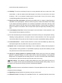
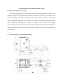
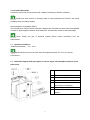
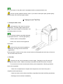
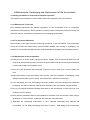
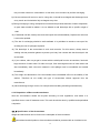
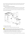
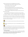
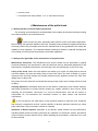
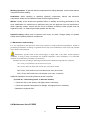
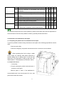
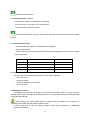
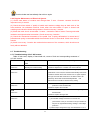
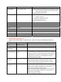
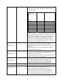
PSP25-SMS-001_EN Instruction Manual PSP25 Power Pallet Truck Operators should read and understand this manual and all warning Labels on power pallet truck before using the truck. Keep the manual for future reference. Release:2010.10 EG-Konformitätserklärung EC Declaration of Conformity Hiermit erklären wir, NOBLELIFT EQUIPMENT Jingyi Road, Changxing, Zhejiang, China We herewith declare Daß die nachfolgend bezeichnete Maschine aufgrund ihrer Konzipierung und Bauart sowie in der von uns in Verkehr gebrachten Ausführung den einschlägigen grundlegenden Sicherheitsund Gesundheitsanforderungen der EG-Richtlinien entspricht. that the following machine complies with the appropriate basic safety and health requirements of the EC Directive based on its design and type, as brought into circulation by us. Bei einer nicht mit uns abgestimmten Änderung der Maschine Gültigkeit. verliert diese Erklärung ihre In case of alteration of the machine, not agreed upon by us, this declaration will lose its validity. Bezeichnung der Maschine: Machine Description: Maschinentyp: Machine Type: Elektrohubwagen Power Pallet Truck PSP25 Einschlägige EG-Richtlinien: EG-Maschinenrichtlinie: 2006/42/EC Applicable EC Directives: EC Machinery Directive: 2006/42/EC Angewandte harmonisierte Normen insbesondere: Applicable Harmonized Standards: EN 1726-1: 1999; EN1175-1: 1998 Herstellerunterschrift/Datum: Authorized Signature/Date: Dec. 29, 2009 Angaben zum Unterzeichner: Title of Signatory: Presiden Table of Contents INTRODUCTION................................................................................................................................................. 1 1 GUIDELINES FOR SAFE OPERATION........................................................................................................ 2 2 OVERVIEW OF THE POWER PALLET TRUCK ......................................................................................... 6 3 TRANSPORT AND TRIAL RUN.................................................................................................................... 9 4 MAINTENANCE, RECHARGING AND REPLACEMENT OF THE ACCUMULATOR .........................11 5 OPERATION ................................................................................................................................................... 15 6 MAINTENANCE OF THE PALLET TRUCK ............................................................................................... 20 7 SCHEMATIC DIAGRAMS OF ELECTRIC AND HYDRAULIC SYSTEM .............................................. 36 Introduction Welcome to use this series of power pallet trucks. This manual gives clear information on how to master safe operation of the power pallet trucks. The safety instructions and important precautions are indicated with the following icons: 1. ---- This icon indicates the existence of a hazard that could result in personal injury if the safety instruction is not observed 2. ---- This icon indicates that a failure to observe the described instruction could lead to equipment damage 3. ---- Refers to general notes and instructions before use. Most parts of the product are made from recyclable steel. The recycling and disposal of cast-offs resulted during using, maintenance, cleaning and disassembling the product has to comply with local regulations without pollution to the environment. The recycling and disposal of the cast-offs should only be operated by specialised personnel in the designated area. The cast-offs such as hydraulic oil, batteries and electronic units, if improperly disposed, may be hazardous to the environment and human health. Due to continuous product improvement, Noblelift reserves the right to make changes in product designs and specifications without prior notice. For the latest product parameters, please feel free to contact us. Note: All parameters provided herein are as of the publication date of the Instruction Manual. 1 1 Guidelines for Safe Operation 1.1 Requirements for the driver: The power pallet truck should only be operated by personnel trained in operating the power pallet truck 1.2 The right, duty and responsibility of driver: Clear with his own right and duty, the driver should be trained in operating the power pallet truck and also knows the contents in this operation manual very well. If the power pallet truck in use is controlled on foot, the driver should wear safety boots during operation. 1.3 Unauthorized persons are prohibited to use: The driver is responsible for managing the power pallet truck in use, and must prevent any unauthorized person from driving or operating the power pallet truck. 1.4 Malfunction and Defects: In case malfunction or defects occurs with the power pallet truck, the driver should immediately inform the supervisor. If the power pallet truck can not be operated safely, e.g. with worn wheels and brake malfunction, always stop using it until repaired completely. 1.5 Safety operation and environment protection The checking and maintenance work described in this chapter should be executed according to the time intervals in the maintenance list. Never modify any parts, especially safety devices of the power pallet truck without permission. Never change the operation speeds of the power pallet truck. All original spare parts from the factory are verified by Quality Assurance Department. Only use spare parts from the manufacturer for the guarantee of the safety and reliability of power pallet truck operation. The replaced material such as oil or fuel should be disposed of according to environment protection regulations. 1.6 Dangerous area: Dangerous area generally refers to these locations, in which power pallet truck or its lifting mechanism (e.g. fork or accessories) is moving, lifting or lowering, thus being dangerous to persons in this area, or in which the truck is handling loads. Generally the scope of this area extends to locations to which the loads or accessories on the truck is lowered. 2 Unauthorized persons must be ordered to leave dangerous areas. The driver should always give warning if there is any risk of human injury. If the warned persons still stay in dangerous area, the driver should stop the power pallet truck immediately. 1.7 Use of the flip down platform and side guard rail for this truck may cause crushing and shearing injuries to personnel. The truck is not designed for use in high-risk environment. 1.8 Safety devices and warning signs:Sufficient attention should be paid to safety devices, warning signs and precautions described in above sections in this manual. 1.9 Driving in public places: The truck is prohibited to drive in public places except for special areas. 1.10 Space between vehicles: Remember to keep a proper distance from the vehicle ahead, since it may stop suddenly at any moment. 1.11 Passengers: Never carry or lift persons with this truck. 1.12 Operation in a lift or loading platform: If the load capacity of the lift or platform is sufficient and the space is enough for power pallet truck operation, they can be used for transportation with the permission from the power pallet truck user. The power pallet truck must be confirmed by its driver himself before entering the lift or loading platform. When entering the lift, the loads must enter ahead. And locate the power pallet truck in a suitable position to prevent from contacting walls around. If passengers take the lift together with the power pallet truck, they have to enter after the power pallet truck enters and stops firmly, and leave before the power pallet truck. 1.13 Pallet truck handling in narrow passageways and work areas: under the particular circumstances that the pallet truck has to pass through a narrow passageway, unauthorized personnel must leave the work area and heavy loads must be kept in specially prepared equipment. 1.14 Operation Management: Driving speeds must be suitable to local conditions. Always drive in lower speed when passing curved passageways, narrow passageways, rotary doors or any obstructed places. The driver should be able to measure by sight and keep enough stopping space from vehicles ahead all the time. It is prohibited to make an abrupt stop (unless in emergency), rapid U-turn and chase with each other in obstructed places. Never operate the 3 truck with the body stretching out of it. 1.15 Visibility: The driver must keep his eyes on moving direction and have a clear view of the road ahead. In case the loads carried block sight of the driver, the truck has to be driven reversely. If this is not practical, another person should walk in front of the truck, giving corresponding guidance and warning to the driver. 1.16 Driving on slopes and ramps: when driving the pallet truck on a slope or ramp through an allowable narrow passageway, make sure that the ground is clean and antiskid. Drive safely on the slopes and ramps specified in the technical specification (Instruction manual) of the pallet truck. Loads on the fork must face the upslope direction. U-type turning or parking on slopes or ramps are not allowed. Pass a ramp at lower speed and get ready for braking at any time. 1.17 Load capacity of the floor: Check if the weight of truck and loads or wheel pressure on the floor exceeds the load capacity of the floor. 1.18 The fork should be kept in the lowest position from the floor during non-transportation driving. Standing or sitting pallet truck. It is better to driver in reverse direction of the fork to get good vision and mobility. Driving with the fork forward may cause unpredictable mobility problems. 1.19 Load characteristic: Goods must be carried in a correct, safe and reliable way. Never carry loads piled higher than the pallet truck’s top or protective devices. 1.20 Speed: Select a suitable speed, depending on floor conditions, visibility and the principle of safety operation. During operation, it is prohibited to speed up, stop and turn suddenly, for that may cause roll-over of the loads and the stacker. 1.21 Driving on loading platform or approach bridge: Before driving the truck onto loading platform or approach bridge of a truck, make sure to check load capacity of the approach bridge and if it is equipped with anti-sliding devices. The driver must also check load capacity of the truck and if there are devices to prevent the truck from moving. 1.22 Safe Parking: Pay attention to safety when parking the truck. Never park the truck on a slope or on a ramp. The fork must be lowered down to the lowest position after parking. Turn off the electric lock and remove the key to prevent unauthorized operation. Please disconnect the wires linked to batteries, if the power pallet truck will not be used for a long time before recharging, 1.23 Signalling: Warning signals can be sent by the horn on the truck. 1.24 Protection shoes: According to EU standard EN-345:1-S1, standard protective shoes must 4 be worn when operating on the power pallet truck. 1.25 Attaching device: Attaching device or equipment that may interfere with or complement the pallet truck’s functions can only be installed with the written approval of the manufacturer. If necessary, permission from local authorities shall be obtained. Revision of the attaching devices without approval may affect the stability and rated load of the pallet truck. Failure to comply with these instructions will invalidate the guarantee. The guarantee is also invalidated if the hand-operated scissor lift pallet trucks are exported by the customer (or a third party) illegally without the consent of Noblelift. 5 2 Overview of the Power Pallet Truck 2.1 Main uses and application scope The PSP25 power pallet truck is specially designed for handling goods on flat roads. It is particularly suitable for high loads and long distance transport, with loads up to 2500kg. Travel motor and steering motor adopt three-phase AC technology, because of which the motor speed can be adjusted smoothly within a wider range and in a more efficient manner than traditional DC motor, completely eliminating the trouble of replacing motor brushes and applying zero-maintenance of the motor. Plus, the technology of helical gears used in the transmission box enables the drive to be more efficient, energy-saving and helps to achieve high acceleration and moving speed. 2.2 Outline drawing and technical parameters 6 PSP25 Features Weight 1.2 Type No 1.3 Power (electric, diesel, gasoline, liquefied petroleum 1.4 Driving mode (hand, pedestrian, stand-on, sit-down, unit-pick) 1.5 Rated loading capacity Q(kg) 2500 1.6 Load centre distance C(mm) 600 1.8 Front overhang distance x(mm) 957(1027) y(mm) 1515(1585) kg 1620/1850 kg 780/200 1.9 Track 2.1 Weight (with accumulator) Electric Stand-on 970(980) wgeel Dimension Capability 2.2 Axle load at full load 2.3 Axle load without loading 3.1 Tires (rubber wheels, high-performance elastomer, 3.2 Tyre size, drive side 3.3 Tyre size, load side 3.4 Dimension of steering wheel 3.5 Wheel numbers (X=driving wheel) Drive side/load 3.6 Wheel track (front) Drive side b10 (mm) 441 3.7 Wheel track (back) load side b11 (mm) 380(505) 4.4 Lift height h3 (mm) 130 4.9 Height of lever in middle position h14 (mm) 1290 4.15 Height of fork when being lowered h13 (mm) 85 4.19 Overall length l1 mm) 4.20 Length of truck body 4.21 Width of truck body b1 (mm) 4.22 Fork dimension s/e/l (mm) 4.25 Lateral distance of fork b5 (mm) 560(685) 4.32 Distance from wheel base centre to ground m2 (mm) 25 4.34 Right angle stacking aisle width, pallet 800X1200 (1200 placed along fork) 4.35 Turning radius 5.1 Driving speed 5.2 Lifting speed Drive side/load side Drive side/load side polyurethane wheels Φ254x82 mm Φ84x93 mm Φ149x55 1x -2/ 2/1x -2/ 4 875 Wa(mm) km/h full load/ no load full load/ no load mm/s Climbing capacity full load/no load % Motor Parking brake 6.1 Drive motor power kw 6.2 Lift motor power kw 6.3 Accumulator, U.K. BS standard, no 6.4 Voltage of accumulator, capacity (discharge rate 5 hours) 6.5 Accumulator weight (+/-5%) Others Turning angle 8.7 / 9.0 6.5/14 2.5(AC) 2.2 4VBS V/Ah kg Battery dimension, length X width X height 8.5 1865(1935) Electromagnetic brake 5.10 Noise heard by the driver 2533(2570) 33.7 /45 Lowering speed full load/ no load Driving and control methods Ast (mm) 60 / 160 / 1150(1220) 35.7/ 18.7 5.8 8.4 796 mm/s 5.3 8.1 2025(2095) 24 / 360 280 mm 728 / 243 / 67 dB(A) <70 ° 180 The table is completed in accordance with regulation VDI 2198 and only technical parameters of standard stacker are provided here. Specifications of non-standard stackers or stackers equipped with accessories or other optional components may be different from the above table. We reserve the right to update the specifications of this stacker. 7 2.3 Technical Standards Continuous noise level should be less than 70dB(A) according to ISO4871 standard. Continuous noise level is an average value of noise measured at the driver’s ear during travelling, lifting and being standby. Electromagnetic Compatibility (EMC) The manufacturer confirms that the stacker complies with EN12895 and other relevant standards on limits of electromagnet radiation and interference, and has been tested on static discharge. Never modify any part of electrical system without written permission from the manufacturer. 2.4 Operation Conditions Ambient temperature: 5°C~40°C Special devices have to be used under a temperature below 5°C or in very humid environment, 2.5 Schematic diagram and description on various signs and nameplate locations of the pallet truck No . 8 Name 1 Button mark of pallet truck’s lifting 2 Emergency stop label 3 Button mark of horn 4 Button mark of pallet truck’s advancing and retreating 5 The nameplate of pallet truck 6 Lifting location label (embedded in mask) Contents on the pallet truck’s nameplate shall be understood before use. If there is quality problems with the truck or you need to order spare parts, please specify serial number of the truck and part number. 3 Transport and Trial Run 3.1 Transport with a crane Load capacity of the crane in use must be sufficient. The load weight equals the net weight of truck plus weight of accumulator; see nameplate plate on the truck. The hook holes are specially designed for transport the truck.(see the right picture). Park the truck in a safe position. Hooks of the crane must be applied at hook holes. Hooks of the crane must be applied at hook holes, ensuring the truck will not be slipped down. During operation, make sure the crane, whose hooks must be applied at hook holes of the truck, do not contact with the truck. 3.2 Trial Run The truck can only use accumulator as power supply. Changing to use AC power will damage the electric circuit. Cables connecting accumulator should be less than six meters. To ensure the truck work normally after delivery and transportation, following operations have to be completed: —Check if the completeness of all parts and components, and check if they are in compliance with requirements. —Check the entire unit for defects and failure, especially the wheels and lifting mechanism. ---Recharge the accumulator immediately. 9 If customers want to replace the accumulator with a new one, make sure that the new accumulator match with the accumulator coulombmeter (or is permitted by service technician of manufacturer). 3.3 Moving the pallet truck in case of driving device failure When towing the truck without driving ability, release electromagnetic brake before moving. —Press the emergency stop button, switch off power and remove the key. — Open the cover and back. — Release 3 screws counter clockwise on the electric motor until the brake does not impede the stacker from moving. Now the pallet truck can move. After arriving at the destination location, recover the stacker to original status. 10 4 Maintenance, Recharging and Replacement of the Accumulator 4.1 Safety procedures for lead-acid accumulator operation The stacker must be parked in a safe location before any operation on the accumulator. 4.1.1 Maintenance Technician Only qualified technicians can perform operations on the accumulator such as recharging, maintenance and replacing. Before operation, carefully read the instruction manuals including the operation manual, replenishment preparation and recharging requirements. 4.1.2 Fire Prevention Measures Never smoke or use open fire when performing operations on the accumulator. The accumulator should be at least two meters away from flammable material when storing or recharging. The location for accumulator storage should be well ventilated and equipped with fire fighting devices. 4.1.3 Maintenance of the Accumulator 1) Keep the nuts on every battery cell dry and clean. Tighten every terminal and cable end, and brush them with grease to prevent corrosion. Exposed cable ends and terminal posts should be covered with a skid-proof insulating cover. 2) Every two cells should be well-connected. Check the nuts on each pole, if loose, tighten the nuts. 3) Keep the surfaces of the accumulator clean and dry. After the completion of recharging, clean spilled acid with cotton yarns or brush, annd clean with a wet towel if necessary. 4) Over recharging and over discharging should be avoided, and fast charging and insufficient recharging are also not allowed. Otherwise the life span of the accumulator may be affected. 5) Do not put conductive objects including metal tools on the accumulator, or short circuit or even explosion may be caused. 6) Never spill any hazardous liquid or solid material on surfaces of the accumulator. When using a densimeter or a thermometer, make sure the surface is clean and clear. 7) Recharge the discharged accumulator in time. Delayed recharging may damage the accumulator. Do not delay recharging more than 24 hours. Recharging of the accumulator 11 may not work outdoors in cold weather. In this case, move it indoors to perform recharging. 8) If the accumulator will not be in use for a long time, it should be recharged and discharged once every month and it should be fully recharged every time. 9) During recharging or using, the liquid level of the electrolyte sinks because of water evaporation, so pure water should be added. It is not allowed to add electrolyte with a specific weight of 1.280. 10) If individual cell fails, identify the cause and repair the cell immediately. Replace the cell when it cannot be repaired. 11) The site for recharging should be well ventilated. It is prohibited to smoke or use open fire, avoiding the risk of hydrogen explosion. 12) The electrolyte in the accumulator is toxic and corrosive. For this reason, always wear a working suit and protection glasses to protect your body from contact with the electrolyte in the accumulator. 13) If your clothes, skin or eyes get in contact with the acid liquid from the accumulator, flush with large amounts of clean water. For skin and eyes, flush with large amounts of clean water and also immediately seek a doctor’s treatment. Acid spillage must be neutralized and treated immediately. 14) The weight and dimensions of the accumulator have remarkable effect on the stability of the stacker. Therefore do not modify the type of accumulator without approval from the manufacturer. 15) Never discharge a large current, for example when travelling and lifting simultaneously. 4.1.4 Disposition of Worn-out Accumulators Worn-out accumulators should be recycled according to local regulations, and stored in a specified zone or cast-off treatment zone. This work should be done by qualified and specialized companies. 4.1.5 Specification of the Accumulator Weight and dimensions can be found on the nameplate of the accumulator. Uninsulated terminal poles on the accumulator should be protected with an insulated cover. 12 When connecting the accumulator and socket, make sure to stop the stacker and put the switch at position “0”. When replacing or installing the accumulator, make sure the accumulator is fixed securely in the battery box. 4.2 Removal and Installation of the Accumulator: Rotate the compression lock, open the accumulator gate and use a hex wrench to release the screws. Take the battery away from the stacker, pull it out onto a previously prepared rack, lock the accumulator and then pull it to the place for charging. The installation method is opposite to that of removal. See figure below: 4.3 Charging of the Accumulator PSP25 series stacker is equipped with a dedicated external charger. Before connecting the accumulator for charging purpose, make sure that the charger, emergency stop switch and electric lock switch are off. Perform charging in a well-ventilated place and keep away from sources of ignition. Charge an idle stacker once a month. Charge the stacker accumulator frequently and regularly. Charge the accumulator immediately after low power sign is shown on ECO smart meter during operation. Turn off the electric lock, remove the key and press the emergency stop button when charging, 13 Charge in an environment that is dry, well-ventilated and away from flames. The external charger is used on the PSP25 for charging process as follows: — Press the emergency stop switch to the off position. — Pull out the connector plug of the accumulator 一 Remove the accumulator gate and then turn on the accumulator locking device. 一 Use a pre-prepared transport device to pull the accumulator to the place for charging. — Now, open all the water-filling plug caps on the accumulator. 一 Connect the output plug of charger with the (input) plug of accumulator connector, and then switch on the charger. The accumulator shall be charged at least once a month when not in use for a long time. Automatic charging process: the stacker uses automatic and smart charging. After the plug on the charger is connected to power, the charging lamp flashes red. The charger can automatically adjust the current flow according to the residual capacity in the accumulator to achieve best charging state. After the accumulator is fully charged, charging indicator flashes green and the charger automatically stops charging and turns off the power. The accumulator needs about 7-8 hours to be fully charged. Check if the accumulator is locked and close the accumulator gate before operating the stacker. Recharging is not allowed before power is running out, otherwise damage may be caused to the accumulator. Open the water-filling plug caps on all the unit cells of the accumulator and ensure good ventilation during charging. Make sure no metal objects are placed on the accumulator. Check all cables connection and connectors for obvious defects. Observe strictly all safety instructions, e.g. replenishment of the accumulator and preparation for recharging. 4.3.1 Balanced Recharging The voltage, electrolyte and its concentration of cells in the accumulator may be different, causing low efficiency of the accumulator. At this time balanced recharging shall be carried out to eliminate inconsistency of cells in the accumulator and to keep the cells in step. Balanced recharging is also necessary in the following cases: 14 1) For accumulator cells with frequent voltage level of 1.7V during discharging. 2) If high current occurs during discharging. For example, driving motor and upgrade motor are used simultaneously 3) The accumulator is not recharged timely after power is running out. 4) Accumulator not used for a long time should be recharged before use. Balanced recharging is recommended to be performed once a month during use. 5 Operation 5.1 Below right is the schematic diagram of operation buttons: 1. Pedal switch 2. Horn switch 3. Control handle 4. Emergency stop switch 5. Master switch 6. Plug 7. Key switch 8. ECO intelligent instrument 9. Steering wheel 5.1.1 ECO intelligent instrument LED function ECO multi-function instrument is equipped with five built-in emission diodes, offering the operator intuitive information of the pallet truck’s status. Accumulator Indicator light (1) 15 The indicator light flashes when the accumulator voltage detected by the controller is no more than 40% of the nominal figure. Wrench indicator light (2) The indicator light flashes in case of the pallet truck’s failure. Thermometer indicator light (3) The indicator light flashes when the controller temperature of the pallet truck is too high. Seat indicator light (4) The indicator light flashes when the driver leaves the seat equipped with a switch. Brake indicator light (5) This indicator light flashes after pedal switch is released. Display function Accumulator capacity status (1) is displayed in the left side of the screen in form of ten grids, with each representing 10% of the total capacity. The number of grids displayed indicates the remaining accumulator capacity. When there is only 40% capacity left, the grids starts flashing. When fault alarm on the controller suggests low accumulator voltage, the accumulator LED on the dashboard starts flashing. The number in the top right box of the screen (2) shows the performance mode used by the controller. Press the button to select the performance mode. When a certain mode is selected, related information will be passed to the traction and pump controller via CAN BUS and be processed. The standard feature is to lower the speed of traction controller in Mode 1, 2, 3 and 4. 4 indicates the highest performance 3 indicates middle-level performance 2 indicates low performance 1 indicates the lowest performance Turtle symbol (3) is usually not displayed, but only shown when the pallet truck is under "soft" state, namely, when its maximum speed and acceleration are being reduced. 16 The number at lower right of the screen (5) indicates the working hours. The field n ext to the hour meter (4) shows which meter is being used. K: Timing starts when electric lock is turned on; S: Timing starts when seat switch is turned on; M: Timing starts when the pallet truck begins to work, namely the time figure will increase upon activation of pump or traction motor. Acceleration level (6) is displayed in eight grids at the middle top of the screen. Display of 1 grid indicates minimum acceleration rate and display of 8 grids indicates maximum acceleration rate, with each grid representing 1 / 8 of the acceleration signal input value. Below the accelerator signal at the centre of the screen is the number showing travelling speed of the pallet truck (7). LCD grid on the left of the hour meter (8) describes the wheel location and turning angle. It also indicates the travelling direction when the pallet truck is in motion. An arrow (9) shows a set travelling direction of the pallet truck. When it moves forward, the arrow points upwards. When it moves backward, the arrow points downwards. A dot will be displayed when it is not moving. 5.2 Starting-up the truck The driver should always make sure that no person is staying in the dangerous area of the pallet truck before starting up and operating the unit or lifting loads. Check before daily start-up —Check the entire unit for defects and failure, especially the wheels and lifting mechanism. — Check if the accumulator is firmly fixed and well-connected. Starting-up the truck —Rotate and turn on the emergency stop switch. —Insert the key in electric lock and turn it clockwise to position “I”. — ECO The coulombmeter shows current battery level —Check the horn. —Check braking function of the control lever. Now the preparation before starting-up is completed. 5.3 Operation of the truck 17 5.3.1 Starting-up, Driving and Parking Be careful during starting up and driving, especially when part of your body stretches out of truck’s outlines. Do not carry any other person during driving. Starting up Start up the truck only when the battery cover is closed. - Rotate the power key switch to ON after entering the cab. - The stacker will move forward or backward according to the direction of thumb switch. The greater the turning angle is, the greater the speed and acceleration rate will be. - Rotate the steering handle to make the wheel turn into the appropriate direction, which can be read on the ECO smart meter on the dashboard. Fully electric steering enables a seamless turning within a scope of 180°. The motor stops automatically when the pallet truck turns +90 °, eliminating any chance of overloading. Driving speed will automatically reduce in the event of steering angle exceeding +20 °, ensuring high driving security of the pallet truck. - Start the pallet truck by stepping on the pedal switch with your left foot to release the electromagnetic brake. Travelling Drive the pallet truck smoothly and avoid sudden start or acceleration. Make sure the pedal switch is always stepped down during driving of the pallet truck. Driving on a slope When carrying loads, drive the pallet truck slowly on a slope, with loads on the fork facing downhill. Braking The braking performance of the pallet truck depends on the ground conditions. The driver must be clear about this point. - After the thumb switch is released or turned to a opposite direction, the motor will run 18 automatically under the generator state to achieve soft braking that protects the electromagnetic brake pad, and to achieve energy recovery. Drivers shall adopt this approach as far as practicable. - Releasing the pedal switch by letting go of the pedal will lead to forced braking of the pallet truck. This method is only used for emergency braking. In case of brake failure, find out the cause and fix it. Turn to professionals for repair if necessary. Never use a stacker with faulty brakes, that would be very dangerous! Try to drive towards a direction opposite to the fork tip to ensure good vision and convenient operation. Emergency stop Pressing the emergency stop switch will stop all electric control functions. - Press the emergency stop switch to interrupt the circuit。 5.3.2 Operation of lifting and lowering loads Before lifting loads, the driver must check if the loads are placed on the pallet completely and the weight of loads does not exceed the loading capacity. Do not transport in full load status for a long time. — Make sure the fork reaches under the loads as far as possible. The fork will rise or fall at a certain speed when you operate the "master switch". Lifting of the fork - When you operate the "master switch" towards the "up" direction, the fork will rise to a level as you need. Lowering of the Fork - When you operate the "master switch" towards the "down" direction, the fork will lower to a level as you need. Safe Parking Pay attention to safety when parking the pallet truck. Never park the truck on a slope or on a ramp. Reduce the fork to the lowest position after parking. 19 — Lower the fork. — Turn electric lock from position “1” to “0” and remove the key. 6 Maintenance of the pallet truck 6.1 Safety operation and environment protection The checking and maintenance work described in this chapter should be executed according to the time intervals in the maintenance list. Never modify any parts, especially safety devices of the truck without permission. Never change the operation speeds of the truck. All spare parts provided by original manufacturer are strictly tested. Only use spare parts from the manufacturer for the guarantee of the safety and reliability of truck operation. The replaced material including oil should be collected and disposed of according to local environment protection and health regulations. 6.2 Safety rules applicable to the maintenance of the pallet truck Maintenance technician: The maintenance and service should only be performed by special personnel trained by the manufacturer. After the technician sent by after-sales department of the manufacturer completed maintenance and servicing work, they should sign on the service log. Lifting of the truck: When the truck needs to be raised up for repair, the lifting device must be safe and reliable, and must be strictly fixed to hook holes. When the truck is raised up, proper measures such as using wedges and wooden blocks must be applied to prevent the truck from sliding down or tilting over. Only when the fork is fixed and connected with strong enough ropes can a hoisting device be used for lifting. Cleaning Operation: Flammable liquid can not be used for cleaning the truck. Before cleaning, take safety precautions to prevent electric sparks (e.g. sparks caused by short circuit). When operating the accumulator, connectors on it must be disconnected. Use soft air suction or compressed air, non-conductive and anti-static brushes to clean electric and electronic components. If you are going to use water spray or high pressure cleaner to clean the truck, all electric and electronic components must be covered carefully in advance because moisture may cause them malfunction. Never use steam nozzles for cleaning. Operation of Electric System: Operation on the electric system should only be performed by specially trained personnel. Before performing any operation on the electric system, precautions must be made to prevent electric shock. When operating the accumulator, connectors on it must be disconnected. 20 Welding Operation: To prevent electric components from being damaged, remove these electric components before welding. Installation: When repairing or replacing hydraulic components, electric and electronic components, make sure to install them back to their original positions. Wheels: Quality of the wheels has significant effect on stability and driving performance of the truck. Modification on wheels can be performed only with the approval from the manufacturer. When replacing wheels, ensure that the truck is levelled as delivery state (wheels must be replaced in pairs, i.e. replace right wheel together with left one). Hydraulic tubing: tubing must be replaced once every six years. Change tubing of hydraulic system when replacing hydraulic components. 6.3 Maintenance and checking It is very important for safe operation of the truck to perform overall professional maintenance. Failure in performing maintenance according to specified interval may cause malfunction of the truck, and potential risk to human and equipment. Maintenance periods listed in this manual apply to single shift a day under normal operation conditions. If using in dusty environment, the ambient temperature varies remarkably or in multi-shift situation, the maintenance period has to be shortened. Maintain the truck according to following maintenance list. Maintenance periods are as follows: W1 = Every 50 work hours, but at least once a week. M3 = Every 500 work hours, but at least once every three months M6 = Every 1000 work hours, but at least once every six months M12 = Every 2000 work hours, but at least once every 12 months Additional operations should be performed in trial run period: (In initial 50 – 100 working hours or after two months) — Check the nuts on the wheels, and tighten them if necessary. — Check the hydraulic components for leakage, and tighten them if necessary. —Replace the hydraulic filter. 6.4 Maintenance list of PSP25 Time interval of maintenance 21 Standard =● W M M M Cooling storage =# 1 3 6 12 # ● Chassis & Main frame 1.1 Check all bearing parts for damages ● 1.2 Check all bolt connections ● Driver: 2.1 Check the drive system for noise and leakage ● 2.2 Check oil level in drive system ● 2.3 Replace lubricant oil 3.1 Check for wear and tear ● 3.2 Check the bearings and make sure they fit well with the wheels ● 4.1 Check the steering control ● 5.1 Check the performance and adjust accordingly 5.2 Check the brake disk for wear ● 5.3 Check the connection of brake and adjust if necessary ● 6.1 Check performance and adjust accordingly 6.2 Visually inspect the loading wheels for blockage 6.3 Check fork tips and pallet support for wear and damages # ● 7.1 Check performance # ● 7.2 Check all connections for leakage and damages # ● 7.3 Check the cylinder for leakage and damages and if the accessories are safe and secure # ● 7.4 Check the oil level. # ● 7.5 Replace hydraulic oil and the filter element # ● 7.6 Check the pressure regulator valve # ● 8.1 Check performance ● 8.2 Check all cable connections for safety, reliability and damages ● 8.3 Check if the amperage of fuses is proper 8.4 Check if the switch and release mechanism is secure and functions properly ● 8.5 Check the speed controller. ● 8.6 Check the warning device 9.1 Check the wear status of the carbon brush and commutator (pump motor) 9.2 Check the safety of additional devices of the motor 9.3 Clean dust in the motor with a vacuum cleaner 10.1 Check the density of acid liquid, capacity and voltage of the accumulator Wheels: Steering system: Braking system Lifting Mechanism Hydraulic system Electric system Motor Accumulator # # ● ● ● # 22 ● ● ● ● ● # ● 10.2 Check the safety devices on terminals and the grease # ● 10.3 Clean the connector of accumulator and check the connection. # ● 10.4 Check the cable for damages, replace if necessary Lubricant oil 11.1 Grease the truck according to time table for filling up lubricant General Test 12.1 Check the grounding connection of electric system ● 12.2 Check the travelling speed and braking distance ● 12.3 Check the lifting and lowering speed ● 12.4 Check the safety device and switch off devices ● 13.1 Perform trial run under rated load ● 13.2 The truck is proved to be safe and reliable to personnel after completion of above maintenance Trial ● # # ● ● If above steps still can not solve problems, please contact after-sales service department of the manufacturer and have the problems solved by specially trained technicians. 6.5 Instruction on maintenance and repair 6.5.1 Preparing the pallet truck for maintenance and repair. To prevent possible accidents during maintenance and repair work, following preparations must be done: —Park the truck safely. —Press the emergency stop switch and disconnect the connectors on accumulator. When operating after fork is rising or pallet truck is lifted, the operator shall adopt measures to prevent falling over or sliding down of the fork and pallet truck. For information on lifting of the truck, see related parts in “Transportation and Trial Run” above. 6.5.2 Open the covers. — Park safely — Press the emergency switch and undo screw 1 as shown in the figure. - Remove panel 4,back 3, first dashboard 6, second dashboard 5 and control panel 5 in turn, and place them beside the stacker. 23 Install in a reverse order. 6.5.3 Check hydraulic oil level —Get the truck ready for maintenance or repairing. —Remove screw 1, then open cover 4 and back 3. —Check hydraulic oil level in oil tank. Check the hydraulic oil level only after the fork and main frame are lowered to their lowest position. 6.5.4 Check electrical fuse —Get the pallet truck ready for maintenance and repairing. — Open control panel 2. —Consult the sheet and check whether all the fuses have appropriate rated current. Change fuses if necessary. Name Protective effect Data FU01 Traction fuse 200A FU02 Lifting control fuse 200A FU1 Control fuse 10A FU03 Steering control fuse 60A 6.5.5 Use Preparation after maintenance or repairing Use the truck only after following operations have been completed. — — — — Clean the truck. Check the brake. Check the emergency stop switch. Check the horn. 6.6 Storage of the truck If the pallet truck has been in storage for more than two months, park it in a dry and antifreezing place. Before that, take all the required actions. The following measures shall be adopted during and after storage. During storing, the truck should better be placed with the wheels off the ground for protecting the wheels and the bearings within wheels. If the storage time is over six months, please consult the manufacturer on additional protection measures. 24 6.6.1 Operations before storing —Clean the stacker thoroughly. —Check the brake. —Check the hydraulic oil level, refill if necessary. —Apply lubricant oil or grease to protect all parts. —Refill grease according to detailed lubrication cycle table. —Recharge the accumulator again. —Disconnect and clean the accumulator. Apply grease on terminal poles on accumulator. Besides these, the accumulator must be protected according to special requirements stated in accumulator instruction manual. 6.6.2 Cautions during storage Every one month: Recharge the accumulator. Operations related to accumulator It is very important to recharge the accumulator periodically. Otherwise, the accumulator will self discharge, resulting complete loss of capacity and the accumulator may become worn-out thoroughly. 6.6.3 Trial Run Again —Clean the truck thoroughly. —Refill grease according to lubrication cycle table. —Clean the accumulator, apply pole lubricant on the terminal poles and reconnect the connectors. —Recharge the accumulator again. —Check if there is moisture in hydraulic oil. If so, replace hydraulic oil. —Start up the truck. Operation of accumulator on the pallet stacker: —If the switches in electric system do not contact well, clean all exposed connectors with contact detergent spray, and repeat this operation to remove oxide layer on these connectors. 25 Conduct brake test immediately after trial run again. 6.6.4 Regular Maintenance of Electrical System (1) Check wear status of contacts and change them if worn. Contactor contacts should be inspected every 3 months. (2) Check the micro-switch of pedal or handle and measure voltage drop at both ends of the micro-switches. No resistance shall be found when the micro-switch is open or closed and crackling sound shall be heard during release. Check once every 3 months. (3) Check the main circuit: accumulator - inverter - connection cable of motor. Ensure good cable insulation and tight electrical connection. Check once every 3 months. (4) Check the mechanical movement of the pedal. See if spring deformation is normal and if potentiometer spring is retractable within the maximum level or to a set level. Check once every 3 months. (5) Check once every 3 months the mechanical movement of the contactor, which should move freely without adhesion. 6.7. Troubleshooting 6.7.1 Troubleshooting of AC1 AC Inverter Table of fault code, display of hand-held unit, cause of fault and corresponding treatment of AC1 AC Inverter: Trouble code Display of hand-held unit and fault A 08 WATCH DOG Cause: Watchdog failure. This is a logical self-diagnosis. Flash once Standby and runtime testing Treatment: Replace the controller if the fault continues. A 13 EEPROM Cause: Failure of memory or logic card storing adjustment KO Cause of fault and corresponding treatment parameters. In this case, the machine automatically shuts down. Flash once Treatment: Switch off the lock and then turn on again. Replace the logic card if the fault continues. If the fault is solved, all previously saved data are automatically deleted. Use hand-held unit controller to restore factory setting. A 17 LOGIC FAILTURE #3 Cause: failure 3 of the logic card: hardware circuit for current protection in the controller fails. Flash once Treatment: replace the controller. A 18 LOGIC FAILTURE #2 Cause: Failure 2 of The logic card: Circuit handling voltage feedback fails. Flash once Treatment: replace the logic card. A 19 LOGIC FAILTURE #1 Cause: failure 1 of the logic card is because: Flash once 1) accumulator voltage increases to more than 45v (accumulator of 24v) or more than 47.5v (accumulator of 36v) due to regenerative braking, leading to overvoltage protection. 2) internal input voltage in the logic card decreases to 11v or 26 less, such problems as true low-voltage, decrease of input voltage due to bad connection of electrical lock, temporary undervoltage appearing because of sudden increase of high-current battery voltage 3) hardware of logic card fails Treatment: fix the failure appropriately according to its cause and pay attention to failures due to cause 1). Contact Dekra company if it happens frequently. A 30 A 31 Flash three times VMN LOW Cause: Factors causing that VMN voltage is too low or too high VMN HIGH may include: Standby and runtime testing of 1) wrong wiring of three-phase power line of motor VMN voltage 2) electrical leakage of motor 3) damage of inverter Treatment: Check if motor wiring is correct and if motor leakage occurs; replace the inverter if damaged. A 38 CONTACTOR OPEN Cause: The logic card drives to the main contactor coil, but the contactor is not closed. Possible causes: Flash six times 1) the connecting cable of coil is cut off or disconnected 2) imperfect contact of contact points in the contactor Treatment: fix the failure appropriately according to its cause. A 53 STBY I HIGH Flash five times Standby testing Cause: Check if motor current is zero. If it is not zero and fault display occurs, the stacker will immediately stop working. Possible causes: 1) The chopper has taken in water or acid 2) Current sensor and its circuit are damaged. Treatment against cause 1): clean up the chopper, rinse it with dry ethanol and blow it try. If the fault still exists, replace the logic card. If it can’t help, replace the power section. Treatment against cause 2): check connections before replacing the logic card. If it can't help, replace the power section. A 60 CAPACITOR CHARGE Flash three times Standby testing. Cause: Capacitor charging fails. WHEN ELECTRIC LOCK IS connected, the inverter charges the capacitor through power resistors. Check if the capacitor is fully charged within stipulated time period. if not, inverter will react by giving alarm and the main contactor won't be closed. Possible causes are: 1) check if the charging resistor is disconnected; if yes, replace the resistor. 2) check if the charging circuit is defective. 3) power unit fails. 4) accumulator problems Treatment: Fix the failure appropriately according to its cause. 27 A 61 TEHERMAL PROTECTION Flash seven times The system keeps testing the Cause: Thermal protection: 1) If controller temperature is not high when the fault occurs, it output of temperature sensor. may be caused by failure of diagnostic circuit of thermal This failure indicates that chopper power unit or thermal detection circuit of the logic card. temperature is higher than 75 °C. At 2) If controller temperature is high when the fault occurs, it may this time the maximum current of be caused by overloading or imperfect cooling of stacker. chopper gradually decreases and Treatment: 1) For cause 1), check with a hand-held controller chopper output will be cut when to see if the actual temperature is not normal. temperature rises to 100°C. For example: 127 °C negative temperature, constant temperature or bouncing temperature during stacker operation. If temperature is abnormal, it may be due to failure of thermal detection circuit of the power unit or logic card. Replace the chopper in this case. 2) For cause 2), check to find out if the real cause of heat is poor working condition or bad heat exchange. Check of heat transfer links including: see if contact surfaces between chopper bottom and mounted bottom plate and between bottom panel and stacker body meet related requirements, and if screws are tightened, and if control box is well ventilated and so on. Operation under braking status may also cause overheating of chopper. Fix failure appropriately according to its cause. A 66 BATIERY LOW Cause: The fault occurs when the accumulator capacity falls Flash thirty-two times Only when the function "BATTERY below 10% and maximum current falls to below 50% due to: CHECK" on the chopper is selected will the accumulator capacity be 1) Over-discharge of real accumulator and low accumulator voltage. 2) Damage of a cell in battery, oxidation of battery pile head checked. The failure occurs. and loose connection of power cord. 3) Imperfect pull-in of the main contactor and voltage drop between main contacts. Treatment: Fix the failure appropriately according to its cause. A 71 HAND BRAKE Cause: The stacker can not start when the handle switch is turned on due to the same reason of AL79 Flash twice Treatment: same as AL79 AL73 THERMIC Cause: Thermal protection. Thermal diagnostic circuit of the Flash seven times SNSOR KO chopper's power unit or temperature sensing circuit of logic card fail. Treatment: Replace the chopper. A 74 DRIVER SHORTED Cause: The controller checks if short circuit occurs in the main contactor drive, causing the failure. Possible reason is Flash six times damage in logic card. Standby testing Treatment: Replace the logic card. A 75 CONTACTOR DRIVER Cause: The main contactor of logic card drive is closed after first 28 Flash six times Standby testing check. Alarm occurs when high level drain of the main contact drive is detected. Treatment: Replace the logic card. COLL SHORTED A 76 Cause: Overload of contactor drive output or short circuit of + BATT probably due to: Flash six times 1) Short circuit of contactor coil or passing through of Testing in electrical locking sustained current of more than 6A. 2) Short circuit of contactor drive cord and + BATT. The fault display indicates overload but not failure of chopper. Re-start the stacker when external failure is eliminated. 3) Failure of logic card Treatment: Fix the failure appropriately according to its cause. A 78 VACC NOT OK Flash four times Test output The output voltage of standby accelerator is 1V higher than the voltage of the accelerator under standby status minimum value stored in the PROGRAM VACC menu probably due to: 1) Disconnection of the potentiometer 2) Damage of potentiometer 3) Programming problem of the accelerator. Treatment: Check the potentiometer and its wiring, and then re-adjust the accelerator and conduct re-programming. A 79 INCORRECT START Flash twice Start-time Testing Cause: Errors in operation sequence. Possible causes are: 1) Sticking of operation micro-switch or handle micro-switch. 2) Incorrect start sequence by driver. 3) Wrong connection of external wires. Replacement of logic card is needed. 4) Data stored in EEROM memory is wrong due to improper operation or interference. For example, changing of safety switch settings will lead to wrong operation sequence. Treatment: Fix the failure appropriately according to its cause. Replace the logic card if the problem still exists. A 80 The Light always on FORW+BACK is Failure occurs when forward request and backward request are THE MACHINE WILL KEEP ON TESTING input into the controller simultaneously. Possible causes are: 1) Cord breakage and wrong wiring method. 2) Such incorrect operations as simultaneous depressing of forward switch and backward switch. 3) Sticking of forward switch or backward switch. 4) Circuit failure of forward or backward input of inverter. Treatment: Fix the failures appropriately according to its cause. Replace the logic card if the problem still exists. A 86 PRDAL WIRE KO Wrongly connected cables of the accelerator unit cause the failure. Flash four times Treatment: Check the wiring of the accelerator unit. A 99 A 248 CHECK UP NEEDED Cause: Warning that check-up time is over and remind the user to perform maintenance. 29 Flash once Flash six times Treatment: check it up and then set check up done to "on" AUX OUTPUT KO Cause: Microprocessor tested the driver of electric brake. Alarm occurs if the drive output state does not match the input signal of the microprocessor. Treatment: Replace the logic card. Flash six times PEV NOT OK Cause: Failure of standard "HM" or MDI PRC output voltage. Possible causes are: 1) Damage of the output transistor. 2) Failure of the logic card Treatment: Replace the logic card. A 242 MOT. TH. SENSOR KO A 244 SAFETY KO A 245 WRONG SET BAT A 246 SAFETY A 247 CAN BUS KO A 249 THERMIC SENS.KO A 250 HANDBRAKE A 251 WAITING FOR NODE A 253 AUX OUTPUT KO 6.7.2 Troubleshooting of EPS-AC0 Table of fault codes, display of hand-held unit, cause of fault and corresponding treatment of EPS-AC0: Trouble code Fault Cause of fault and corresponding treatment A 216 MICRO SLAVE #8 A 217 MICRO SLAVE #3 A 218 CLOCK PAL NOT OK Treatment: replace the controller. A 219 STEPPER Flash three times MISM A 220 MOTOR LOCKED Cause: failure occurs in case of inconsistency between the frequency and voltage difference of stepping motor connection (for example: the frequency of connection d and q in stepping motor is high while the voltage difference is low). Under normal conditions, the frequency of a stepping motor will increase as voltage difference enlarges. Treatment: replace the controller. Cause: fault alarm occurs if the current of steering motor keeps close to the maximum current for more than 1 second. Flash once MOTOR Flash twice Treatment: check if the motor is mechanically locked. a simple method is to set the DEBUG OUTPUT to "11" A 221 Flash once MICRO SLAVE #4 Cause: fault alarm occurs under any of the conditions below: (apply to open-loop system only) fault alarm occurs when the rotation direction of stator voltage as detected by the microprocessor is opposite to the speed signal of stepping motor. (Apply to closed-loop system only) fault alarm occurs when rotation direction of the stator voltage as detected by microprocessor is opposite to the pre-set direction. Treatment: replace the controller. 30 A 222 FB POT LOCKED or Flash three times FB SENS LOCKED CAN Bus Cause: when a feedback potentiometer is applied, the fault will occur if the potentiometer value is adjusted immediately but the feedback potentiometer (CPOT ON CNB # 6) fails to react (or reacts oppositely). When the trigger switch is applied, set the ENCODER CONTROL to "OFF". The fault will occur if t real-time control potentiometer changes but feedback encoder does not count changed value. Treatment: when a feedback potentiometer is applied, check for mechanical looseness of the feedback potentiometer and blocking of the steering wheel. Make sure the contact brush falls within the maximum mechanical limit of the steering wheel. In addition, failure may also occur during installation and when the motor rotation direction is not same as expected. When the trigger switch is applied, check if mechanically looseness occurs to the encoder and if blocking occurs to the steering wheel. The problem is easy to solve: set the DEBUG OUTPUT to “11”. A 223 JERKING FB POT Flash three times A 225 CURRENT GAIN Flash four times A 226 NO SYNC A 227 1)SLAVE COM.ERROR Flash once 2)NO SYNC CANBUS Cause: failure occurs if the value change of feedback potentiometer in 16 milliseconds is greater than 0.3v. The fault is usually caused by an inconstant voltage signal output by the feedback potentiometer. Treatment: change the signal of the feedback potentiometer. Cause: failure occurs in case of default setting of the gain compensation parameter (ADJUSTMENT # 03 and ADJUSTMENT # 04) in the current amplifier (for example, there is no adjustment on maximum current value) Treatment: adjust the maximum current value of the Zapi controller. 1) Cause: the main microprocessor and the subordinate microprocessor communicate through local serial interface. Fault alarm occurs if the main microprocessor can't send information to the subordinate microprocessor via serial interface. Treatment: replace the controller. 2) Cause: in every 16 milliseconds, internal code makes a cycle. The signal of main microprocessor will rise and fall, and then be sent to the microprocessor (SYNC). Fault alarm occurs if the microprocessor detects no edge signal in more than 100 milliseconds. A 228 Flash three times POSITION ERROR Cause: failure happens during testing of the feedback potentiometer. 1) When the feedback potentiometer and feedback encoder is being used simultaneously and the steering angel of the steering wheel is controlled: pre-set value of FEEDBACK ENC and FEEDBACK POT in the test menu shall be the same. Fault alarm occurs if the difference between the two values exceeds 20 degrees (SET MAX FB POT-SET MIN FB POT is equivalent to 180 degrees). 2) When the trigger switch and feedback encoder are being used simultaneously, fault alarm will occur if the area (the area for trigger switch installation and configuration) does not match the encoder calculation. This area is realized by reading of the feedback sector in 31 the test menu: the encoder value is calculated by reading of the wheel angle in the test menu. Special note: actually two trigger switches are applied. A 237 WAITING DATA Not flashing(warning) guide wheel deflection confirmed area angle(degree) confirmed feedback area -22 TO +22 1ST OR 4TH 3.13 V OR 1.88 V +23 TO +67 1ST 3.13 V +68 TO +112 1ST OR 2ND 3.13 V OR 4.39 V +113 TO +157 2ND 4.39 V +158 TO -158 2ND -157 TO -113 3RD -112 TO -68 3RD -67 TO -23 4TH OR 3RD 4.39 V OR 0.62 V 0.62 V OR 4TH 0.62 V OR 1.88 V 1.88 V Treatment: check if the potentiometer is connected correctly. if the trigger switch connects CNA # 2 and CNA # 3, test if the wiring is correct, set AUX FUNCTION 11 correctly, and check if the motor bearing sensor (encoder) has slip (bearing sensor has two loop connections: one connected to the rotor shaft and the other connected to motor enclosure). When no slip exists, check if the wiring structure of two connections is reliable. This warning only occurs when the CAN BUS is set as “present”. Fault alarm occurs if closed electric lock EPS-AC0 fails to correctly receive a list of parameters sent by the traction controller via CAN BUS. The steering motor is not driven and the safety relay remains disconnected when the fault exists. A 238 EPS NOT ALIGNED Not flashing(warning) Cause: this fault will cause disconnection of the traction controller. Fault alarm occurs during initial align if the straight forward condition isn't set in 6s after start. The safety relay will be cut off and the traction controller will stop working in case steering is not activated after 6s. A 239 WAITING FOR TRAC Not flashing(warning) A 240 KEY OFF A 241 ENCODER ERROR Flash three times Cause: closed electrical lock EPS-AC0 shall permit a signal of closed safety contacts and operating mode changing from the traction controller. Fault alarm will occur if the permission becomes unacceptable. The occurrence of warning disables operation to be activated and keeps the safety relay cut off. Cause: fault occurs if ENCODER CONTROL is set to “ON” and the actual frequency can not reach the pre-set value. Treatment: below are the two conditions that may exist separately: software encoder resolution does not match the actual encoder resolution, or the two channels of the encoder are connected in a wrong manner. The latest method of fixing the fault is to swap the two channel connections in the 32 encoder. A 242 Q LINE SENSOR KO Flash three times Cause: fault occurs if the average voltage of the stepping motor connections (connected to CNA # 8) is not 0. Voltage of stepping motor connections is a sine wave with null voltage. Treatment: check the connections of the stepping motor. In particular, measure if the resistance between CNA # 8 and the accumulator’s negative terminal (when the stepping motor is at rest) is low (close to 30OHMS). A 243 D LINE SENSOR KO Flash three times Cause: fault occurs if the average voltage of the stepping motor connections (connected to CNA # 9) is not 0. Voltage of stepping motor connections is a sine wave with null voltage. Treatment: check the connections of the stepping motor. In particular, measure if the resistance between CNA # 9 and the accumulator’s negative terminal (when the stepping motor is at rest) is low (close to 30ohms). A 244 GAIN EEPROM KO Flash four times A =245 DATA Flash thirty-two times ACQUISITIO N A 246 MICRO SLAVE KO Flash once Cause: adjustments on the gain compensation parameter of the current amplifier (ADJUSTMENT # 03 and ADJUSTMENT # 04) are redundant processings of rewritable memory. Each adjustment is actually a re-position of rewritable memory 3. Fault alarm occurs if the value at position 3 is inconsistent. Treatment: return the controller to Zapi for adjustment on maximum current. Cause: failure occurs when the motor resistance is set or the gain compensation parameters (maximum current after adjustment) of the current amplifier are adjusted. Treatment: switch on and off the electrical lock again. Cause: in application of the stepping motor, failure alarm occurs if the direction of stepping motor detected by the main microprocessor and that detected by the subordinate microprocessor do not match. Steering errors detected by the main microprocessor and the direction detected by the subordinate microprocessor do not match. In addition, the main microprocessor detects no restrictions on steering device while the subordinate microprocessor detects certain restrictions. Treatment: replace the controller. A 247 CAN BUS KO Cause: fault occurs only when CAN BUS is set as present. EPS-AC0 must receive all the information from the traction controller. If there is no information transmission in more than 1 second, a fault will occur. Flash twice Treatment: check the CAN BUS communication system and analyze the structures from traction controller to steering controller. A 248 S.P OUT Flash three times RANGE OF Cause: this fault occurs due to wrong adjustment on the potentiometer (CPOC1 ON CNA # 9, CPOC2 ON CNA # 8). When single output potentiometer is selected, the fault will occur if the output signal falls beyond the range of 0.8V to 4.2V. When dual potentiometer is selected, the fault will occur if the sum voltage of outputs falls beyond the range of 4.5V to 5.5V. 33 Treatment: check wiring of the potentiometer. Fault alarm will occur in case of damaged connection points of potentiometer. Flash three times F.B OUT OF RANGE A 250 MICRO SLAVE A 249 Flash once Cause: the fault is caused by wrong signal of the potentiometer feedback (CPOTON CNB # 6). Alarm occurs if CPOT falls beyond the range of 0.3V to 4.7V. Treatment: check the wiring of the feedback potentiometer. Alarm will occur in case of wiring damage in the feedback potentiometer. Cause: alarm occurs if the information on the bus between the main and subordinate microprocessors is fixed at “OXFF” (subordinate microprocessor can not upgrade the bus configuration state). Treatment: replace the controller. KM OPEN A 251 Flash once Cause: if the security contact is closed as detected by the main microprocessor, but is open as detected by the subordinate microprocessor, fault alarm occurs. Treatment: replace the controller. KS OPEN A 252 Flash once Cause: if the security contact is open as detected by the main microprocessor, but is closed as detected by the subordinate microprocessor, fault alarm occurs. Treatment: Replace the controller. A 253 KM CLOSED Cause: when electric lock is closed, fault alarm occurs if the subordinate microprocessor finds security contact to be closed before setting of main microprocessor. Treatment: when electric lock is closed, fault alarm occurs if the voltage of connection CNA # 5 (K1) is within 12V. In fact, K1 should connect to the positive terminal of accumulator voltage (not 12V) if the security contact is open. Check for hardware problems or replace the controller. KS CLOSED Cause: when electric lock is closed, fault alarm occurs if the main microprocessor finds security contact to be closed before setting of subordinate microprocessor. Treatment: when electric lock is closed, fault alarm occurs if the voltage of connection CNA # 4 (NK1) is within 12V. In fact, nk1 should connect to the negative terminal of an accumulator voltage (not 12V) if the security contact is open. Flash once A 254 Flash once Check for hardware problems or replace the controller. If above steps still can not solve problems, please contact the after-sales service department of the manufacturer and have the problems solved by specially trained technicians. 6.6.5 Lubrication points in routine maintenance 34 ◆= Refill opening ◇=Draining opening Lubrication Cycle Table Lubrication Cycle 1000 h 2000h No. Refill point 1 Bearings in wheels 2 Rotary bearing 3 Main frame post L 4 Hydraulic system C O D 5 Gear box C O F 500 h L A L E B L=Lubricating C=Checking O=Replacing Description tables of oil and lubricant Lubricant type Lubricant Name >-15℃ <-15℃ Lubricated area A Lubricant grease 2# Jinzhi grease 2# Jinzhi grease Bearings, sleeves, joints B Lubricant grease 2# Jinzhi grease 2# Jinzhi grease Main frame grooves C Lubricant grease 2# Jinzhi grease 2# Jinzhi grease Chain D Hydraulic Oil 40# Hydraulic Oil 30#Hydraulic Oil Hydraulic system E Lubricant grease 2# Jinzhi grease 2# Jinzhi grease Rotary bearing F Gear oil W85-90 Gear oil W85-90 Gear oil Gear box 35 7 Schematic Diagrams of Electric and Hydraulic System 7.1 PSP25 circuit diagram Following are names of electric components 1 GB Accumulator 14 S5 Button switch 2 Mp Pump motor 15 HA Horn 3 KMp Pulling motor contactor 16 ACC Fingertip potentiometer 4 YV Lowering solenoid valve 17 S4 Micro-switch 36 5 Mt Traction motor 18 S3 Master switch 6 YB Electromagnetic brake 19 SQA SQB Proximity switch 7 Ms Steering motor 20 SM Emergency stop switch 8 FU01 FU02 Fuse 21 B Stepping motor FU03 FU1 VD1 VD2 Diode 22 P Intelligent instrument 10 VD3 VD4 Es Steering controller 23 SW11 Pedal Switch 11 Et Traction controller 24 F Discharge module 12 SA Key switch 25 KM Contactor 13 MF1 MF Fan 120X12 9 7.2 Schematic diagram of PSP25 hydraulic system P T M 37