1
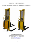
OPERATION & SERVICE MANUAL
S SERIES STACKER WITH POWERED DRIVE & POWER LIFT
Vestil Manufacturing Corp.
2999 North Wayne St., Angola, IN 46703
. Fax: 260-665-1339
Ph: 260-665-7586
E-mail: [email protected]
Website: www.vestil.com
1
General
Read and follow the instructions contained in
this operating manual without fail!
Only trained, well-informed personnel, who have been instructed in accordance with this
operation manual, may use or work on the machine.
Liability or guarantee is waived if:
The instructions in this operating manual are not observed.
The high-lift stacking truck is operated, cleaned or maintained incorrectly.
Alterations to the functions are carried out without the consent of manufacturer.
Original spare parts are not used.
Safety instructions
This chapter informs the user about residual dangers relating to the correct use of the
products. It contains generally valid safety instructions which must be observed.
Safety instructions relating to specific actions or situations are listed prior to the respective
action and/or description of the situation in the chapter.
Principles
This product complies with state-of-the –art technical standards and recognized safety
regulations, but there are still dangers which may occur which must be considered.
Only operate the product in a perfect condition and observing the information contained in
the operating manual.
The operator is responsible for integrating the product with as little risk as possible into his
working environment. This obligation continues through every phase of the products
lifespan, beginning at the planning stage. Residual dangers are to be minimized.
Only trained, competent personnel who have been instructed using the operating manual
and the product are permitted to work with the truck.
The operating manual must be understood (responsibility, checking)
Declaration:
I have read this manual and, in particular, have taken note of the caution.
Name
Date
Signature
2
Specification
SPECIFICATION
Capacity
S-62-FF
S-62-AA
S-62-FA
2000 lbs.
2000 lbs.
2000 lbs.
Fork Lift Height
62"
62"
62"
Fork Dimension
42x5.9x2 3/8"
42x4x1-1/4""
42x5.9x2 3/8"
26-3/4"
26-3/4"
26-3/4"
1"
1"
1"
2-9/16"
Overall fork width
Ground Clearance
Lowered Fork H.
3-3/8"
2-1/8"
H. Overall Extended
81-7/8"
81-7/8"
81-7/8"
26-1/2x30x29-3/4"
26-1/2x30x29-3/4"
26-1/2x30x29-3/4"
Head Dimension
Loading Center
23-5/8"
23-5/8"
23-5/8"
Wheel Base
44-3/4"
44-3/4"
44-3/4"
Turning Radius
55"
55"
55"
Support Wheel
Φ4x2"
Φ4x2"
Φ4x2"
Front Wheel
Φ3-1/8x3-3/8"
Φ3-1/8x3-3/8"
Φ3-1/8x3-3/8"
Drive Wheel
Φ10x3-1/8"
Φ10x3-1/8"
Φ10x3-1/8"
Overall Size
68x30x82
69x46x82
68x46x82
Lift
Load
2.95"/s
2.95"/s
2.95"/s
Speed
Unload
5.9"/s
5.9"/s
5.9"/s
Lower
Speed
Load
4"/s
4"/s
4"/s
Unload
2"/s
2"/s
2"/s
Travel
Speed
Load
5km/h
5km/h
5km/h
6km/h
6km/h
6km/h
Drive Motor
Unload
24V/700W
24V/700W
24V/700W
Lift Motor
24V/2.0KW
24V/2.0KW
24V/2.0KW
Controller
1207A-4102
1207A-4102
1207A-4102
Battery
2x12V/70Ah
2x12V/70Ah
2x12V/70Ah
DC 24V/6A Soneil
DC 24V/6A Soneil
DC 24V/6A Soneil
950 lbs.
990 lbs.
970 lbs.
6%
6%
6%
10%
10%
10%
35-1/2"
52"
52"
Battery Charger
Weight
Load Grade ability
Unload Grade ability
Width of Aisle
Note: The load capacity is based on the situation when the center of the gravity is
located at the center of length of forks. When the center of gravity of goods is out
of the center of forks, the load capacity will be lessened compared to the center.
3
CO N T E N T S
General …………………………………………………………………………………
2
Specification ……………………………………………………
3
Receiving instructions ……………………………………………………………… 5
Safety Notes ……….…………………………………………………………………… 6
Product description …………………………………………………………………
Designated use …. … …... … ……………………………………………………
Signs on the Truck ………………………………………………………………..
7
7
8
Transport ………………………………………………………………………………… 9
Operation ………………………………………………………………………………
10
Operation ………………………………………………………………………………
Operating elements ………………………………………………………………
Safety elements …………………………………………………………………
Driving, braking and horn…………………………………………………………
Lifting and lowering ………… ……………………………………………………
Traveling …………………………………………………………………………..
Taking up the load…………………………………………………………………
Driving on sloping surfaces………………………………………………………
Maintenance and repair ……………………………………………………………
Trouble shooting …………………………………………………………………
Changing batteries ………………………………………………………………
Changing motor controller ……………………………………………………..
Belly switch trouble shoot ………………………………………………………
Maintenance daily/before use, monthly, annually …………….……………..
Maintenance and care of the load chains ……………………………………
Chain inspections …………………………………………………………………
Temporary lay-up …………………………………………………………………
11
12
13
14
15
16
17
18
18-22
23-24
25-31
32-49
50
51
52
53
Parts List ………………………………………………………………………………… 54-60
4
Receiving Instructions
Every unit is thoroughly tested and inspected prior to shipment. However, it is possible
that the unit may incur damage during transit. If you see damage when unloading, make a
note of it on the SHIPPER RECEIVER.
Remove all packing & strapping material, inspect for damage. IF DAMGE IS EVIDENT,
FILE A CLAIM WITH THE CARRIERIMMEDIATELY! Also, check fork size, type of power
unit, etc., to see that the unit is correct for the intended application.
Warnings & Safety Instructions
Insure that all employees understand and follow the following instructions
•
Read and understand the owner’s manual before using or servicing the stacker.
•
Do not use the stacker if any damage or unusual noise is observed.
•
Improper use of this lift truck could result in injury and damage to load or
equipment.
•
Always watch the stacker and any load on it carefully when it is being used or
moved.
•
Avoid sudden stops or quick turns to turns to prevent accidental tipping of the
load.
•
Load must be centered and evenly distributed on the forks.
•
Park the truck on level surfaces and not in the way of other products
•
When parked, lower the load fork completely.
•
When parked, push E-switch push-button down.
•
Do not perform any modifications to the stacker without the manufacturer’s
approval. Failure to receive authorization for changes to the equipment could
void the warranty.
•
Do not use brake fluid or jack oil in the hydraulic system. If oil is needed, use an
anti-wear hydraulic oil with a viscosity grade of 150 SUS at 100°F, (ISO 32 @
40°C), or a non-synthetic transmission fluid.
•
Use only replacement parts either supplied or approved by the manufacturer.
5
Safety notes
Symbols and pictograms used
In addition to the text and illustrations, this operating manual contains various symbols
which should draw attention to the safety requirements.
They generally have the following appearance:
Signal wording
DANGER
WARNING
CAUTION
Explanation
Warning of an imminent danger!
Non-observance cause death or serious injury
Warning of a possibly incoming dangerous situation.
Non-observance may cause death or serious injury.
Warning of a possibly incoming dangerous situation.
May also be used for warnings of major damage to property.
Other definitions:
DIRECTION
IMPORTANT
Marks recommendations for use and other useful information.
Does not warn of dangerous situations.
Warns of a harmful situation.
Non-observance may cause damage to material.
Used symbols and pictograms
Possible danger to
file and limb or
machine!
Do not step onto when
load is raised!
Danger of crushing!
It is forbidden to ride
on the truck!
Do not reach into
running motor!
Suspension points for
transport of truck!
Wear safety shoes
Important
Wear helmet
Suspended
warning!
6
load
Product description
Designated use
The stacker is designated for lifting, lowering and transportation of loads according to
the specifications of the identification plate.
The stacker is to be used on hard level surfaces.
To move the stacker between buildings, warehouses etc
The gradient of the slope must not be more than 10%
Make sure load is not loose or unstable.
Do not pick up loads on tips or forks or edge of platform.
Do not overload.
The road surfacing must be solid and have a good grip.
Travel routes must offer sufficient load-bearing capacity for the loaded truck.
The stacker is not suitable for continuous use in cool-houses!
Ambient conditions
Temperature
From
To
Degree of humidity
Permitted
floor
incline
Loaded
Unloaded ¹
Dimensions and weights
Mass (dead weight)
m
14
113
≤70
°F
°F
%
Max. 0.5
Max. 2.0
%
%
480/750
kg
WARNING!
The user is responsible for determining the actual load bearing capacity of a high-lift
stacking truck. This can depend on the user, the condition of both the floor and the high-lift
stacking truck and the regularity of the maintenance intervals.
7
Product description
8
Removing from the pallet or lifting the product
Lifting belt specification— Use polyester lifting sling or nylon sling and
hoist with a minimum of 2,000 lb. capacity.
CAREFUL
To pick up the unit only use overhead hoist, forklift or loading
crane with sufficient carrying capacity!
Refer to the identification plate for the weight of the truck.
DANGER
When unloading the truck, all personnel should be cleared
from area.
9
OPERATION
Visually inspect stacker for damaged and worn parts, before
stacker is taken into operation. Authorized person should read
and understand all instructions
The lifting truck is ready for immediate use once the packaging has been removed.
The battery is full and charged.
The hydraulic tank is full.
The driving gear is filled with oil filling for approx. 200 operation hours.
The steering roller and the running rollers are equipped with bearings which do
not require maintenance; all mast rollers are also free from maintenance.
Caution!
Pedestrian controlled industrial trucks may only be operated by persons who
have been satisfactorily instructed in operating the truck and have proved their
ability to operate the truck to the responsible representative of the operating
company.
The first driving attempts should take place on level and spacious surfaces.
Recommendation:
The operator who is to maneuver the truck and is to control the lifting
mechanism should be allowed to practice, when unloaded, until they can
safely operate these functions.
Only then should they undertake the loading, transporting and unloading of
load.
10
Operation
11
Operation
12
Operation
Driving
Pull up the red push button of the E-switch
Tilt the Control handle to driving position, the
locking brake is released
If you release Control handle, this returns to the
vertical start position, the truck brakes and the
locking brake activates
The truck is steered via the Control handle
Brake:
This stacker is equipped with a magnetic brake
that is applied between 10-15 degrees of the
vertical position and between 85 -90 degrees of the
lower position in the vertical operating of the
handle. The brake can be operated at any point in
the lateral operating of the handle. When you
release your hand from the handle, it will resume
neutral position automatically, and will activate the
brake. Always make sure that the brake is in work
before operating the stacker. When parked, always
put the handle in the full vertical position with the
brake applied and forks lowered.
Horn:
A horn is located on top of the handle.
13
To raise and lower
The following are generally valid for the lifting and lowering procedure:
The red operating button of the EMERGENCY STOP pushbutton must be pulled
upwards
Lifting and lowering movements are initiated by pressing the pushbuttons on the
handle head.
There are four buttons located on the two sides of the handle. Each side
of the control has one button for raising the forks and one button for lowering
the forks. Always make sure when lifting that the load is within the capacity
rating of your truck and that the load has been stacked safely on the pallet.
Also, make sure that there is no one standing near the forks when raising or
lowering. It is also important to make sure that the length of the forks
corresponds to the opening in the bottom of the pallet. The load rollers must
be placed between boards so when you raise the forks, the pallet will not be
broken or damaged. Always make sure when entering the pallet that the forks
are in the fully lowered position. Be careful when lifting pallets that are too
short or too long for the truck
Warning
It is forbidden to climb or reach into any moving parts of the lifting truck-e.g. the
lifting frame, thrust units, lifting mechanisms etc.
14
Travel
The butterfly switch controls the direction and speed of the lift truck.
Rotating the butterfly control towards the forks moves the truck in the forward
direction. Rotating the butterfly control away from the forks, moves the truck
in the reverse direction. The control is progressive – the further you rotate the
control, the faster the truck will travel.
DIRECTIONAL SPEED CONTROL THROTTLE
Emergency reverse safety button
At the top of the handle is a red safety reverse button. The button is
designed to change the travel direction away from the operator when
depressed. The truck will stop moving away from the operator when the
button is released. When the fork truck is traveling forward (away from the
operator) the button has no effect when activated.
If the belly switch becomes jammed or stuck, it will move forward (away
from the operator) for a maximum of 3 seconds at which time the control circuit
will become disabled until the handle is re-set to the full up or full down position
and the belly switch is returned to normal operation.
BELLY SWITCH (SAFETY REVERSE BUTTON)
15
Operation
Lifting load
CAUTION!
Before lifting a load to be transported, ensure that the
load does not exceed the carrying capacity of the
truck.
The nominal carrying capacity and lifting heights can
be viewed in the load diagram.
Ensure that the load can be taken up in a compact and
stable manner. Slipping or falling of the load must be
avoided.
The load must not project into the lifting frame.
The load must be centered and evenly distributed on
the forks.
The load must not project more than 50mm over the
end of the lifting forks.
Transporting the load
CAUTION!
Raise the load only slightly to transport
For safety reasons (view) transport only in a forward
direction
Only when lifting up or lowering down the load it is
permissible to drive forwards or in reverse with a
raised load
Lift up or lower down loads on level surfaces
When unloaded, move stacker only with forks lowered
16
Operation
Driving on sloping surfaces
17
Maintenance and repair
TROUBLESHOOTING GUIDE -- ______
Warning: Before performing any task, always block drive wheel off of the ground.
Consult the factory for problems at time of installation, or for any problems not addressed
below.
Problem:
Unit doesn’t move when controls are
used.
Unit will not charge
Unit will not go forward; reverse
works; belly switch just kills unit
(does not go forward and time out)
Possible cause(s):
Battery voltage low (<17)
Charge batteries.
Problem with motor controller
(check for LED flash code on side
of controller)
Consult diagnostics
page/factory
Fuse blown
Remove back shroud and check
fuses (3 fuses).
Charger malfunction
Verify output voltage on charger,
will only get a reading when
connected to batteries; should be
approximately 28 volts.
Bad batteries
Load test batteries
Broken wire, or loose connection
Locate Pin 2 on Molex connector at
motor controller. Trace wiring to
contactor and verify connection.
Contactor bad, motor controller bad
Unit will not go reverse; belly switch
works (i.e. when the handle is in
operating range and rotating
throttle in reverse and the belly
switch is hit, the unit moves
forward and times out)
Action:
Broken wire, or loose connection,
contactor bad, motor controller
bad
18
When forward is depressed, there
should be 24 volts on this wire
from Molex connector to the
contactor, if not, the motor
controller may be bad; consult
diagnostics page/factory. If 24
volts is present at contactor,
verify ground connection. If
ground is good, remove both wires
and check with ohm meter;
resistance should be
approximately 38 ohms. If it’s
open or zero, the contactor should
be replaced.
Same as above; except locate Pin 3
on Molex connector on motor
controller…and follow procedure.
Problem:
Unit will not go forward, or reverse,
but belly switch still functions
properly.
Possible cause(s):
Broken wire, or loose connection,
bad motor controller,
Throttle assembly bad
Unit will not move forward, or
reverse, and the Belly switch will
not function, unit does turn on as
indicated by the battery gage
lighting up.
Action:
Locate Pin 6 on Molex connector at
the motor controller. Try to drive
the unit in forward, there should
be 0 to 5 volts (5 v is full throttle)
at this pin. If there is voltage and
the unit does not move, the motor
controller may be bad, consult
diagnostics page/factory. If
there is no voltage, trace the
wiring back towards the tiller head
and check voltage on each side of
connectors. Continue this until
bad connection is found.
If the connections are all good, and
there is no voltage coming out of
throttle assembly, then the
throttle assembly may be bad.
Verify there is 24 volts going into
the assembly and that there is a
good ground. If there is still no
output voltage for pin 6, replace
throttle assembly. See Fig. 1
Blown fuse
Verify fuses are good, replace if
blown.
Broken wire, or loose connection
Locate Pin 7 on Molex connector at
the motor controller. Trace wire
back up to tiller head and verify
continuity all the way to the
throttle assembly. Repair any
loose connections.
If there is continuity up to the
throttle assembly, then check the
ground wire that comes off of Bon the motor controller (3rd
terminal down). Add more length
to this wire if necessary, and
re-terminate with a ring terminal.
Unit will not go forward; the belly
switch functions; reverse works.
Broken wire, or loose connection,
bad motor controller
Locate Pin 11 on Molex connector at
the motor controller. Try to drive
the unit in forward; there should
be 24 volts at this pin. If there is
voltage and the unit does not
move, the motor controller may be
bad, consult diagnostics
page/factory. If there is no
voltage, trace the wiring back
towards the tiller head and check
voltage on each side of
connectors. Continue this until
bad connection is found.
Bad throttle assembly
If the connections are all good, and
there is no voltage coming out of
throttle assembly, then the
throttle assembly may be bad.
Verify there is 24 volts going into
the assembly and that there is a
good ground. If there is still no
output voltage for pin 11, replace
throttle assembly. See Fig. 1
19
Problem:
Unit will not reverse; belly switch
does not function; forward ok
Possible cause(s):
Broken wire, or loose connection,
bad motor controller
Bad throttle assembly
Belly switch does not function;
forward ok; reverse ok
Broken wire, or loose connection,
bad motor controller
Bad belly switch
Unit will not reverse. The unit only
goes forward for about 1 second
and dies when the handle is pulled
down. When the handle is re-set
and pulled down the unit will move
forward again then die.
Stuck Switch
20
Action:
Locate Pin 12 on Molex connector at
the motor controller. Try to drive
the unit in reverse; there should
be 24 volts at this pin. If there is
voltage and the unit does not
move, the motor controller may be
bad, consult diagnostics
page/factory. If there is no
voltage, trace the wiring back
towards the tiller head and check
voltage on each side of
connectors. Continue this until
bad connection is found.
If the connections are all good, and
there is no voltage coming out of
throttle assembly, then the
throttle assembly may be bad.
Verify there is 24 volts going into
the assembly and that there is a
good ground. If there is still no
output voltage for pin 12, replace
throttle assembly. See Fig. 1
Locate Pin 13 on Molex connector at
the motor controller. Try to drive
the unit in reverse, and hit the
belly switch… there should be 24
volts at this pin. If there is
voltage and the unit does not
move, the motor controller may be
bad, consult diagnostics
page/factory. If there is no
voltage, trace the wiring back
towards the tiller head and check
voltage, or continuity on each side
of connectors. Continue this until
bad connection is found.
If the connections are all good, and
there is no voltage, then the
switch may be bad. Verify there
is 24 volts going into the switch.
If there is still no output voltage
for pin 13, replace the switch.
The belly switch is stuck on.
Tap the orange assembly to see
if the switch can be freed. If
this doesn’t work, disassemble
the tiller head by removing 3
screws from bottom. Slightly
loosen up the two screws that
hold the switch in place, this
may free the switch. If it is still
stuck, contact the factory for a
replacement switch.
Problem:
Unit will not raise; motor does not
run
Possible cause(s):
Loose wire
Bad solenoid
Upper limit switch out of adjustment
Blown fuse
Batteries discharged
Action:
Verify 24 volts at coil when
raise is pushed, if no
voltage; trace wiring
back to till her head
looking for voltage on
each side of the
connectors until the bad
connection is found.
If voltage is present at the solenoid
and the unit does not rise, remove
the two wires to the coil and
measure the coil resistance. It
should be around 19 ohms. If it’s
open, or shorted replace the
solenoid.
Bypass upper limit switch and see if
the unit raises…DO NOT TAKE IT ALL
THE WAY UP… If it does rise,
verify the limit switch is normally
closed and will open when
activated. If the limit switch is ok,
try to adjust the switch accordingly
so that the units raise height is
approximately 7 to 8”
Check fuses above motor controller
Unit will not raise; motor runs
Lower solenoid stuck on
Unit will not lower
No hydraulic oil
Loose wire; bad coil
Re-charge batteries
Check to see if the lowering switch is
stuck on. If it is, remove the tiller
head via 3 screws on bottom and
replace switch, or tap on switch to
see if it can be freed up.
Re-fill hydraulic oil
Verify 24 volts at coil when lower is
pushed, if no voltage, trace wiring
back to tiller head looking for
voltage on each side of the
connectors until the bad
connection is found.
If voltage is present at the coil and
the unit does not lower, remove the
connector to the coil and measure
the coil resistance. It should be
around 39 ohms. If it’s open, or
shorted replace the coil.
Upper limit switch out of adjustment
Loosen hydraulic line at pump to
relieve pressure build up.
Re-adjust limit switch so unit stops
at 7 to 8 inches above the ground.
Look for binding in chain or rollers
Unit keeps blowing fuses when the
raise button is pressed
Shorted solenoid for motor raise
21
Remove the wire to the solenoid coil
on the pump motor. Measure the
resistance; it should be around 19
ohms. If it is nearly zero ohms
replace the solenoid.
Problem:
Possible cause(s):
Action:
Unit will not reverse; belly switch
does not function; forward ok
Broken wire, or loose connection,
bad throttle assembly, bad motor
controller.
Locate Pin 12 on Molex connector at
the motor controller. Try to drive
the unit in reverse; there should be
24 volts at this pin. If there is
voltage and the unit does not move,
the motor controller may be bad,
consult factory. If there is no
voltage, trace the wiring back
towards the tiller head and check
voltage on each side of connectors.
Continue this until bad connection
is found. If the connections are all
good, and there is no voltage
coming out of throttle assembly,
then the throttle assembly may be
bad. Verify there is 24 volts going
into the assembly and that there is
a good ground. If there is still no
output voltage for pin 12, replace
throttle assembly.
Lifting height is not longer achieved
Hydraulic oil level is too low
Re-fill hydraulic oil when forks are
lowered.
Unit jerks when lifting
Air in the system
Open vent screw on the lift cylinder
with forks lowered all the way down.
Lift forks with vent screw open until
oil is free from air bubbles. Close the
vent screw
Forks raise, then drift down
Check valve or Solenoid valve leaking
(contamination holding open the
lowering valve or the check valve)
Remove & inspect.
. Remove any load from the forks.
. Remove the nut holding solenoid coil
on the valve stem, and then unscrew
the valve from the manifold.
. Inspect the valve for contaminants,
and the valve’s o-rings and back –up
washers for cuts, tears, and other
damage.
. With valve immersed in mineral
spirits or kerosene, use a thin tool
such as a small screwdriver or a small
hex wrench to push the poppet in and
out several times from the bottom
end of the valve. The valve should
move freely, about 1/16” from closed
to open position. If it sticks in, the
valve stem could be bent and will
need to be replaced if it doesn’t free
up after cleaning. Blow the valve off
with a compressed-air gun while again
pushing the poppet in and out.
22
Filename:
Changing Batteries in S-62 Stacker
VESTIL MFG. CO.
Model: S-62/AA/FF/FA
Instructions for Changing the Batteries, estimated time, 15 min.
READ ALL INSTRUCTIONS BEFORE PROCEEDING!
Only qualified personnel should work on this equipment!
Lock out all potential energy sources before attempting this installation; turn off the
unit and remove the key.
Warning!
!
Working with or near lead acid batteries is dangerous. Batteries contain
sulfuric acid and produce explosive gases. A battery explosion could result in
loss of eyesight or serious burns.
!
Do not smoke or allow a spark or flame near batteries. Charge batteries in
locations which are clean, dry, and well-ventilated. Do not lay tools or
anything metallic on top of any battery. All repairs to a battery must be
made by experienced and qualified personnel.
!
When working with batteries, remove personal items such as rings, bracelets,
necklaces, and watches. Batteries can produce enough energy to weld
jewelry to metal, causing a severe burn.
!
Always have fresh water and soap nearby in case battery acid contacts skin,
clothing, or eyes.
!
Operating the battery with a low battery voltage can cause premature motor
contact failure.
!
Do not expose the lift or charger to rain or adverse conditions.
!
Replace defective cords or wires immediately.
!
Check the battery’s water level frequently if this applies to your battery type.
!
Make sure the battery charger is unplugged from 115vac source.
Battery Charger Operating Instructions
Plug the charger into a standard 115V receptacle. If an extension cord must be
used, keep it as short and as large as possible. A small cord will decrease the output
of the charger due to the voltage drop in the line. This will increase the charging time.
It can also cause the 115V cord to overheat.
When properly connected, the charge LED will indicate the status of charge current
flowing to the battery, as follows: Power LED is always green when charger is plugged
in. The status light is as follows:
Red only – the charger is providing full output to the battery.
Yellow – the charger is “topping off” the battery.
Green – the charger is providing a “float,” or maintenance, charge.
Remember to unplug the charger before moving the equipment.
and other equipment.
23
Failure to do so could cause damage to cords, receptacles
Troubleshooting:
If the unit does not operate, check all of the wiring connections to make sure they’re both
mechanically and electrically sound – specifically at the battery, and the motor.
A fully-charged lead acid battery in good condition at room temperature should read 12.65
volts. At 11.9 volts it is considered to be fully discharged and in need of charging. When
checking battery voltage, wait at least 1\2 hour after the charger has been turned off before
checking the battery’s voltage.
If the batteries aren’t being charged by the charger, check the output
charger fuse. Verify fuse is good with an ohmmeter, or close visual
(ohm meter best). Fuse is a 10Amp 250 Volt; GBD 10A. If it is
good, check the battery’s state of charge with a voltmeter. The
charger must be connected to the battery in order to read the output
voltage of the battery charger. Depending on the state of charge of
the batteries, the voltage should be somewhere around 27 to 28 volts
dc.
If it is determined the batteries are dead, and need replaced, change the
batteries.
Tools Required:
14mm wrench, or crescent wrench
Regular flat bladed screw driver
24
Filename:
Changing Motor Controller in S-62 Stacker
VESTIL MFG. CO.
ModelS-62-AA/FF/FA
Instructions; Changing the Motor Controller in; estimated time, 30 min.
READ ALL INSTRUCTIONS BEFORE PROCEEDING!
Only qualified personnel should work on this equipment!
Lock out all potential energy sources before attempting this installation; turn off the
unit and remove the key.
Warning!
!
Working with or near lead acid batteries is dangerous. Batteries contain
sulfuric acid and produce explosive gases. A battery explosion could result in
loss of eyesight or serious burns.
!
Do not smoke or allow a spark or flame near batteries. Charge batteries in
locations which are clean, dry, and well-ventilated. Do not lay tools or
anything metallic on top of any battery. All repairs to a battery must be
made by experienced and qualified personnel.
!
When working with batteries, remove personal items such as rings, bracelets,
necklaces, and watches. Batteries can produce enough energy to weld
jewelry to metal, causing a severe burn.
!
Always have fresh water and soap nearby in case battery acid contacts skin,
clothing, or eyes.
!
Operating the battery with a low battery voltage can cause premature motor
contact failure.
!
Do not expose the lift or charger to rain or adverse conditions.
!
Replace defective cords or wires immediately.
!
Check the battery’s water level frequently if this applies to your battery type.
!
Make sure the battery charger is unplugged from 115vac source.
Troubleshooting:
If it has been determined the motor controller needs to be replaced, the following procedure
can be used.
Tools Required:
2x 14mm wrench, open face
Philips head screwdriver
8mm wrench
25
Filename:
Changing Motor Controller in S-62 Stacker
VESTIL MFG. CO.
ModelS-62-AA/FF/FA
Verify power if off to the unit; key switch off!
Remove yellow cover; two screws on top.
The Campro motor controller is shown here.
26
Filename:
Changing Motor Controller in S-62 Stacker
VESTIL MFG. CO.
ModelS-62-AA/FF/FA
The wiring must be marked
The wiring should be marked in a unique way to remember where it all goes when re-connecting.
One possible method is shown below.
Remove the two 14mm bolts holding the motor controller mounting plate to the frame.
27
Filename:
Changing Motor Controller in S-62 Stacker
VESTIL MFG. CO.
ModelS-62-AA/FF/FA
Two bolts, one front and one back.
Remove the Molex connector from the motor controller.
28
Filename:
Changing Motor Controller in S-62 Stacker
VESTIL MFG. CO.
ModelS-62-AA/FF/FA
Remove the motor controller wiring with two 14mm wrenches.
29
Filename:
Changing Motor Controller in S-62 Stacker
VESTIL MFG. CO.
ModelS-62-AA/FF/FA
Wiring shown here removed.
Remove 3x 8mm screws holding the motor controller to the back plate with a Philips screwdriver,
and 8mm wrench. 1 screw in back and two in the front.
30
Filename:
Changing Motor Controller in S-62 Stacker
VESTIL MFG. CO.
ModelS-62-AA/FF/FA
Remove the motor controller, and replace with a new controller by reversing the above steps.
Verify the 4 spade terminal connections are still good on the forward / reverse motor contactor.
The contactor is just below the motor controller.
31
Filename: Belly Switch trouble shoot
VESTIL MFG. CO.
Model: S-62-AA/FF/FA
Instructions for Changing the Tiller Assembly; S-62-AA/FF/FA estimated time, 30 min.
READ ALL INSTRUCTIONS BEFORE PROCEEDING!
Only qualified personnel should work on this equipment!
Lock out all potential energy sources before attempting this installation; turn off the
unit and remove the key.
Warning!
!
Working with or near lead acid batteries is dangerous. Batteries contain
sulfuric acid and produce explosive gases. A battery explosion could result in
loss of eyesight or serious burns.
!
Do not smoke or allow a spark or flame near batteries. Charge batteries in
locations which are clean, dry, and well-ventilated. Do not lay tools or
anything metallic on top of any battery. All repairs to a battery must be
made by experienced and qualified personnel.
!
When working with batteries, remove personal items such as rings, bracelets,
necklaces, and watches. Batteries can produce enough energy to weld
jewelry to metal, causing a severe burn.
!
Always have fresh water and soap nearby in case battery acid contacts skin,
clothing, or eyes.
!
Operating the battery with a low battery voltage can cause premature motor
contact failure.
!
Do not expose the lift or charger to rain or adverse conditions.
!
Replace defective cords or wires immediately.
!
Check the battery’s water level frequently if this applies to your battery type.
!
Make sure the battery charger is unplugged from 115vac source.
32
Filename: Belly Switch trouble shoot
VESTIL MFG. CO.
Model: S-62-AA/FF/FA
Troubleshooting:
If the unit does not operate, check all of the wiring connections to make sure they’re both
mechanically and electrically sound – specifically at the battery, and the motor.
A fully-charged lead acid battery in good condition at room temperature should read 12.65
volts. At 11.9 volts it is considered to be fully discharged and in need of charging. When
checking battery voltage, wait at least 1\2 hour after the charger has been turned off before
checking the battery’s voltage.
If the batteries aren’t being charged by the charger, check the output
charger fuse. Verify fuse is good with an ohmmeter, or close visual
(ohm meter best). Fuse is a 10Amp 250 Volt; GBD 10A.
If it is
good, check the battery’s state of charge with a voltmeter. The
charger must be connected to the battery in order to read the output
voltage of the battery charger. Depending on the state of charge of
the batteries, the voltage should be somewhere around 27 to 28 volts
dc.
If the batteries are fully charged, and the units belly switch is not functioning the following
procedure will show how to…
A) Replace the tiller assembly which contains the belly switch and throttle controls.
B) Troubleshoot belly switch mechanism itself.
The following tools will be required:
5mm allen wrench
Philips bladed screw driver
Small Regular flat bladed screw driver
Filename: Belly Switch trouble shoot
VESTIL MFG. CO.
33
Model:
S-62-AA/FF/FA
S-62-XX; verify this is the unit you are working on.
Make sure E-switch is off (pushed down). Fig.2
34
Filename: Belly Switch trouble shoot
VESTIL MFG. CO.
Model: S-62-AA/FF/FA
This is the top side of the tiller.
Fig3
This is the driver side of the tiller, looking at the belly switch.
Filename:
Fig 4
Belly Switch trouble shoot
35
VESTIL MFG. CO.
Model: S-62-AA/FF/FA
This is the bottom side of the tiller handle. 3 allen head screws need to be removed. Fig5
Lift the front top edge of the tiller cover up.
Filename:
Fig6
Belly Switch trouble shoot
36
VESTIL MFG. CO.
Model: S-62-AA/FF/FA
Carefully pull the belly switch back off of the tiller while tipping the front up.
Fig 7
Filename:
Belly Switch trouble shoot
37
VESTIL MFG.
CO.
Model: S-62-AA/FF/FA
The tiller assembly cover should come off, just be careful not to drop it and rip out the wiring
from the connectors. At this point, the tiller throttle assembly can be replaced
with a new one by just unplugging the two connectors. Or, if the problem appears to be in the
belly switch itself, further breakdown of the assembly can continue to search for the problem.
Fig 8
Unplug the two connectors from the tiller throttle assembly.
38
Fig9
Filename: Belly Switch trouble shoot
VESTIL MFG. CO.
Model: S-62-AA/FF/FA
Remove Philips screw on throttle. Fig10
Throttle wheel will then pull off. Take note of the orientation of the wheel on the shaft.
orientation is shown here. Fig 11
39
Correct
Filename: Belly Switch trouble shoot
VESTIL MFG. CO.
Model: S-62-AA/FF/FA
Do the same on the other side, taking note of the orientation of the two plastic bushings. If the
throttle wheel had a tendency to stick, contact Vestil Manufacturing for replacement bushings. Fig
12
The front of the red cover should be connected via the gray nub.
Filename: Belly Switch trouble shoot
VESTIL MFG. CO.
40
Fig 13
Model:
S-62-AA/FF/FA
To remove the red cover, use a small screwdriver and carefully lift the plastic up over the gray nub.
Fig 14
Do the same on the other side, and remove.
Fig 15
Filename: Belly Switch trouble shoot
VESTIL MFG. CO.
41
Model:
S-62-AA/FF/FA
This should expose a spring. This spring has a specific orientation. When assembled the spring
sets in the red cup on the inside of the red belly cover. Fig 16
The other side of the spring fits over the gray plastic nub above the switch. Fig 17
Filename:
Belly Switch trouble shoot
42
VESTIL MFG. CO.
Model: S-62-AA/FF/FA
Another picture of the nub, spring not shown. At this point, verify the solder joints are in tact
and the two wires are attached to the switch as shown below. Also verify the belly switch is not
stuck in. You should be able to push on the switch and the actuator will move freely in and out,
you should here a click as you do this. If the switch is stuck in contact Vestil Manufacturing for
replacement options. Fig18
Solder
connection
Belly Switch
actuator
Solder
connection
Replace any broken/missing components. To assemble, press the red belly switch cover back on
the tiller head seating the red holes over the gray nubs. Basically the opposite of the procedure in
Fig. 17, but without a screwdriver. Fig 19
Filename: Belly Switch trouble shoot
VESTIL MFG. CO.
43
Model:
S-62-AA/FF/FA
The spring can be pushed into position.
Fig. 20
This is the spring shown not seated completely. Push the spring into the pocket, and over the
gray plastic nub. Fig21
Filename: Belly Switch trouble shoot
VESTIL MFG. CO.
Model: S-62-AA/FF/FA
44
Install bushings.
Fig22
Put throttle thumb wheels back on.
Fig23
Filename: Belly Switch trouble shoot
VESTIL MFG. CO.
Model: S-62-AA/FF/FA
45
Install Philips screw.
Fig24
Re-installing the tiller cover is basically reversing steps Fig 5 thru 9; with the following
precautions/steps.
Make sure red tabs on each side goes on top of black nubs when installing tiller cover on the
handle. Fig 25
Red Tab on
each side
Filename: Belly Switch trouble shoot
VESTIL MFG. CO.
Model: S-62-AA/FF/FA
46
Black nub for right side shown here; and the next photo
fig 26
The red tab slides over the top of this black nub on each side when installing the tiller throttle
assembly back on the handle. Fig 27
Plastic Nub
Filename: Belly Switch trouble shoot
VESTIL MFG. CO.
Model: S-62-AA/FF/FA
47
This shows sliding the red tabs over the black nub.
This is basically the reverse of Fig7.
Fig29
Red tab
Black nub
This is the top front where the two connectors are.
off so the wires do not get pinched. Fig28
Make sure they are on each side of the stand
Stand
off
between
connectors
Filename: Belly Switch trouble shoot
VESTIL MFG. CO.
48
Model:
S-62-AA/FF/FA
Gently push the tiller throttle assembly in place. Again, it’s just reversing steps 5 through 9 to
get the tiller throttle assembly back on the handle. Re-install the 3 allen screws, verify no
switches are sticking, and that the thumb wheel moves freely. Turn the unit on and verify
operation. This completes the assembly.
5mm allen
screws;
3
places
Maintenance and repair
(A) BEFORE EACH USE INSPECT FOR THE FOLLOWING:
49
1)
2)
3)
4)
5)
6)
7)
8)
9)
Frayed wires
Oil leaks
Pinched or chafed hoses
Damage or structural deformation to the structural members, the cylinder brackets,
etc.
Unusual noise or binding, or evidence thereof.
Proper functioning of all limit switches, including those on the perimeter pinch
point guard (if applicable)
Horn works
Load chain, check for mechanical damage, check for play (slack chain)
Battery, keep the surface of battery clean and dry. Make sure battery is secured
against slipping
(B) INSPECT MONTHLY FOR:
1) The oil level. Oil should be 1-1/2” to 2” below the reservoir’s fill hole with the lift in
the fully raised position
2) Worn or damaged hydraulic hoses and electrical wires
3) Pivot point wear
4) Roller’s looseness and wear
5) Integrity of retaining rings on all the rollers and at all pivot points
6) Looseness, wear, or damage to the front rollers & drive wheel, bearings, mounting
hardware, or surface material
7) Proper functioning of any hand-or foot-operated mechanisms
8) Proper water level in the battery
9) Unusual noises or movement during operation
10) All the information, safety, and wearing labels being in place and in good condition
11) The need to clean off dirt and debris
(C) YEARLY INSPECTIONS
1) The oil should be changed if the oil darkens, becomes gritty, or turns a milky color
(indicating the presence of water). Replace with anti-wear hydraulic oil with a
viscosity grade of 150sus at 100°F, (ISO 32 at 40°C ). Ex:AW 32 or HO 150
hydraulic oil, or a non-synthetic transmission fluid. You may use a synthetic
transmission fluid if you flush the system with the synthetic fluid before filling the
reservoir.
2) Check chain and chain connections for any mechanical damage
3) Clean upright channels and mast rollers, & grease slightly.
4) Check magnetic brake travel, & if necessary change brake rotor
5) Check carbon brushes for any wear in the lift motor, & if necessary change carbon
brushes.
Maintenance and repair
Maintenance and care of the load chains
50
In normal use the load chains should be re-lubricated every 250 operating hours; in the
event of heavy soiling, moisture and very high prolonged loading, re-lubrication should be
effected after 100 operating hours. If subject to corrosive media the chain should be
cleaned and lubricated immediately.
Chain lubrication, chain conservation
Flyer chains are correctly lubricated and are in a perfect state if:
The chain is free of exterior soiling.
When touching the chain, your finger is wetted with oil. This assures that the lubrication of
the chain links is sufficient.
Type of lubricant
A low-viscosity mineral – machine – or engine oil or synthetic oil should be used. The
viscosity of the lubricating oil is to selected so that it remains low viscose at all ambient
temperatures encountered.
Under normal temperature conditions, lubricating oils with a viscosity of SAE 20 to SAE 40
would be appropriate.
Lubricating methods
The lubricant can be applied by means of brush, paint brush or also using compressed air
spray devices. When using spray cans, please make sure the following basic requirement
is fulfilled:
- After the thinner has vaporized, a viscosity conforming to the above-mentioned
recommendation (type of lubricant) must be met.
Cleaning the chain
If operation leads the chain to suffer so heavily from soiling that the penetration of the
lubricating oil cannot be guaranteed, the chain must be cleaned.
This is only to be effected with paraffin derivatives such as diesel fuel, petroleum,
cleaner’s naphtha etc.
Do not clean with steam injectors, cold cleaners or even corrosive and acidic substances.
They can directly lead to chain damage.
If the chains have to be cleaned with steam injectors, please contact our customer
service.
Maintenance and repair
51
Chain inspections
Chains used in stackers should be inspected at least once a year or every three months if
exposed to severe contamination or high continuous loading stress.
We recommend that attention be paid to the following points:
1. Unusual noise
2. Surface rust
3. Linkage rust
4. Stiff links
5. Distorted pins
6. Loose link pins
7. Damage
8. Broken link plates
9. Broken pins
10. Contamination
11. Stretching
Even with the optimum amount of lubrication, it is impossible to prevent a chain from
stretching.
Wear extends only to that part of the chain which is led over the chain
sprocket/guide sprocket. Thus, when checking for wear, only check the area need
be inspected.
According to the regulations currently in force, a chain is deemed to be worn if it has
stretched by 3%.
If safety issues are particularly critical or a potential hazard is dependent on a single chain,
we consider it necessary to replace it if it is stretched by even 2%.
Measuring procedure
To measure elongation through wear, that part of the chain which runs over the chain
sprocket/guide sprocket must be positioned in the stretched area. With the aid of a
measuring rod, measure a section approximately 1 meter in length.
The number of divisions in the measured area, multiplied by the chain divisions, gives the
nominal measurement.
The length extending beyond this measurement represents the wear, which is limited to a
maximum of 3% over the nominal length.
An elongation through wear of 3% is reached if 33 links of the chain in use measure the
same length as 34 links of a new chain.
Chain replacement
If two chains are used as a pair on the affected machine, both should always be changed
at the same time.
The installation and removal of chains should be carried out with all the care appropriate
to any item of safety equipment.
Chains may only be repaired by authorized specialist personnel.
We do not recommend the lengthening of safety-type lifting chains, since the inserted
chain link will not have been pre-stretched.
Our product liability will be invalidated if a repaired chain is assembled from sections
bearing different silver label numbers.
Maintenance and repair
52
Temporary lay-up
If, for operating reasons, the stacker is laid up for more than two months, the
following instructions are to be carried out:
Place the stacker on blocks so that all the wheels are raised from the floor.
In this way, they will be prevented from becoming permanently misshapen.
Clean the stacker thoroughly.
It may be necessary to support the lifting gear in a suitable manner, so as to relieve
any stress on the load chains.
Check the hydraulic fluid level, replenish if necessary.
Grease the stacker thoroughly.
Clean all bright and moving parts with a thin film of oil and grease respectively.
Store the stacker in a dry, frost-proof, dust-free place.
Do not use plastic sheeting to cover the stacker otherwise condensation could form
under it.
Additional operations for vehicles with integral electrical systems
Disconnect the batteries from the stacker electrical system.
Charge the batteries.
Clean the top of the battery case and terminals.
Grease the terminals lightly with terminal grease.
Check the electrolyte level, top up if necessary (not applicable to maintenance-free or
gel batteries).
Recharge the batteries every 90 days; gel batteries every 6 months.
Spray a suitable contact spray on unattached electrical contacts.
Return to service after a lay-up
Thoroughly clean and grease the stacker.
Remove the film of protective grease.
Check the hydraulic fluid tank and hydraulic fluid for condensation, if necessary carry
out a fluid change.
Inspect hydraulic hose lines for brittleness.
Test the functions of the vehicle, particularly the safety equipment.
Part list
Electric wiring
53
Part list
Electric circuit
54
55
Part list
S-62 Electric component list
NO
Name
Code
Specification
Qty
1
Battery
DP
12V/70Ah
2
Controller
KZQ
1207A-4102
2PCS
1PC
3
Drive motor
M1
DC24V/0.7KW
1PC
4
Lift motor
M2
DC24V/2.0KW
1PC
5
Lift motor contactor
J1
MZJ200S 24V
1PC
6
Drive motor contactor
J2
MZJ200S 24V
1PC
7
Direction contactor
J3.1
DC88-1 24V
1PC
8
Direction contactor
J3.2
DC88-1 24V
1PC
9
Control circuit fuse
FU1
Ø6X30 10A
1PC
10
Hydraulic circuit fuse
FU2
150A
1PC
11
Drive circuit fuse
FU3
100A
1PC
12
Electromagnetic clutch
L1
DC24V/28W
1PC
13
Solenoid valve
L2
DC24V/16W
1PC
14
Horn
LB
DL1216
1PC
15
Power meter
MC
DC24V
1PC
16
Throttle
TSQ
ETR711-230
1PC
17
Diode
D1
IN5408
1PC
18
Diode
D2-D8
IN4007
7PCS
19
Battery charger
CDQ
24V/15A
1PC
20
Key switch
S1
S001
1PC
21
Emergency stop
S2
ZDK31-250
1PC
22
Clutch micro switch
S3
TM1703
1PC
23
Forward/backward switch
S4
TM1703
1PC
24
Back-run safety device button
S5
KW2-OZ
1PC
25
Lift limit switch
S6
KW2-OZ
1PC
26
Lift switch
S7,8
KW2-OZ
2PCS
27
Horn switch
S9
KW2-OZ
1PC
28
Low switch
S10,11
KW2-OZ
2PCS
29
Power plug
DC110V/200A
2PCS
30
Electric wire
RV16mm2
31
Electric wire
RV0.5mm2
56
Part list
Hydraulic Circuit Diagram
57
Part list
58
Part list
59
Part list
60