1
SERVICE MANUAL 5793
WEIGH RAIL
TYPE IV
September, 1975
B-10/84-100-1138-2
PRINTED IN USA
UNION SWITCH & SIGNAL DIVISION
AMERICAN STANDARD INC./ SWISSVALE, PA 15218
SERVICE MANUAL 5793
WEIGH RAIL
TYPE IV
September, 1975
B-10/84-100-1138-2
PRINTED IN USA
UNION SWITCH &SIGNAL DIVISION
AMERICAN STANDARD INC./ SWISSVALE, PA 15218
m
UNION SWITCH & SIGNAL
TABLE OF CONTENTS
SECTION
I
II
III
IV
v
VI
VII
PAGE
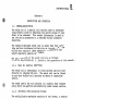
DESCRIPTION AND OPERATION
1.1 GENERAL DESCRIPTION
1.1.1 Main Rail Section (UM377531)
1.1.2 Deflection Multiplication
System
1.1.3 Side Plates (UR451060-1201 and
UM349734) .
.
1.2 OPERATION
1.1.1 Operation Sequence
1. 2 .~ 2 Contacts
1
2
2
2
INSTALLATION
2.1 GENERAL INSTRUCTIONS
5
5
ADJUSTMENT
3.1 CONTACTS
3.1.1 Standard Contact Settinqs
3.1.2 Five Weight Catagories
3.1.3 Master Adjustment Screw
3.1.4 External Parts
6
6
6
1
1
1
7
9
9
LUBRICATION
4.1 WEIGHT RAIL DISASSEMBLY
4.2 WEIGHT RAIL LUBRICATION
4.3 WEIGHT RAIL ASSEMBLY
10
10
10
11
LUBRICATION SPECIFICATIONS
5.1 SPECIFICATION NO. M-7680-2
(UJ41593)
5.2 SPECIFICATION UA41229
5.3 SPECIFICATION M-7611-01 (UA41099)
5.4 SPECIFICATION NO. M-7450-01
(UA41097}
12
GENERAL MAINTENANCE IN~TRUCTIONS
6.1 WEIGHT RAIL
6.2 CONTACTS
6.3 HEATER
14
14
14
14
APPENDICES
15
ii
12
12
12
13
UNION SWITCH & SIGNAL
m
SECTION I
DESCRIPTION AND OPERATION
1.1 GENERAL DESCRIPTION
The weigh rail is a special rail section used in automated
classification yards to determine the weiqht ranqes of cars
about to be processed. This weight information is used to
set the ceiling pressures in a retarder durinq automatic
operation.
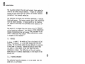
The specially designed weigh rail is ·seven feet four inches
long and has a horizontal milled slot at its midpoint. The
milled slot contains a lever mechanism, sensitive to the
weight exerted by passing car wheels.
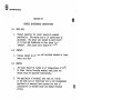
The main components of the weigh rail are as follows:
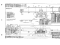
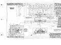
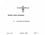
(Refer to Dwg. F451059-Sh. 2, listed in the appendices of this manual}.
1.1.1
Main Rail Section (UM377531)
The weigh rail is rectangular in cross section and will bolt
directly to 140 pound RE rail. The weigh rail can be fitted
to any size standard rail sections by means of compromise
joints.
The steel used in the rail.section is a special heat treated
alloy which will perform satisfactorily under severe service.
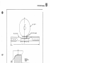
1.1.2
Deflection Multiplication System
The multiplication mechanism consists of two levers, a suooort
bracket and four contact actuating screws (see Figure 1).
Its purpose is to multiply rail deflection caused by the
weight of the car wheel and indicate this weiqht bv ooeratinq
the proper contact.
The lever mechanism is attached to the side plate and protected
by the controller box. The side plate is dowel fitted to the
stationary {lower) part of the rail. One end of the primary
lever is always in contact and thus moves with the vertical
deflection of the rail head. The opposite end of the primarv
lever positions the secondary lever through the master
adjusting screw. Four individual adjusting screws (figure 2)
are set in the opposite end of the secondary lever. These
screws operate four contacts which are provided for liqht,
medium, heavy, and extra heavy weight cars. As one faces the
open controller box, reading from left to riqht, are the extra
heavy contact, the light contact, the medium contact, and
finally the heavy contact.
1.1.3
Side Plates (UR451060-1201 and UM349734)
The slot cut through the center of the rail is covered by side
plates which are bolted directly to the rail section.
5793, p. 1
UNION SWITCH & SIGNAL
The side plates protect the slot and internal lever mechanism
from dirt and other foreign elements. a-rings are installed
between the side plates and rail section to further increase
protection of the internal mechanism.
The controller box houses the controller mechanism, a terminal
. block and a heater. The heater prevents frost from interfering
with the contact movement. A toggle switch in the junction
box adjacent to the weigh rail provides on-off control of the
heater.
The weigh rail is shipped from the factory with all internal
wiring connections completed.· The external wiring connections
between the controller box and junction box, are made at the
time of installation with control cable UN451060-1901, which
is shipped with the equipment.
1. 2
OPERATION
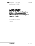
As shown in figure 1, the weigh rail has a horizontal milled
slot at its midpoint. As a car wheel passes over the rail
section, the rail portion above the slot deflects in relation
to the lower rail section. Maximum deflection occurs when
the wheel is at the center of the slot where the lever
mechanism is located. The deflection of the rail section
above the slot is directly proportional to the weight of the
passing car.
1.2.1
Operation Sequence
The mechanical operating sequence, as a car passes over the
weigh rail, is as follows:
A downward deflection o.f the rail section above the slot
produces a corresponding displacement of the primary lever.
The primary lever pivots on bearing Y, causing an upward
movement of the master adjustment screw on the end of the
primary lever.
The secondary lever pivots on bearing x, producing a downward
movement of the four individual adjustment screws.
The downward movement of the individual adjustment screws
closes the corresponding electrical contacts.
1.2.2
Contacts
Four contacts are provided (liqht, medium, heavy, and extra
heavy). The individual adjustment screws and electrical
contacts are adjusted so that a liqht weiqht car will close
only the light contact. A medium weight car will close
both the light and medium contacts. A car in the heavy weiqht
class will close the light, medium, and heavy contacts.
5793, p. 2
UNION SWITCH & SIGNAL
A
CAR WHEEL
w
RAIL SECTION
0
0
DEFLECTED SHAPE
0
0
0
0
INDIVIDUAL
ADJUSTMENT
SCREW
ORIGINAL
POSITION
NYLON
INSULATION
DEFLECTED
POSITION
, . . . . . . . _ _ _ CONTACT>
-
TO
EXTERNAL
CIRCUIT
SECTION A-A
Figure 1. Weigh Rail Schematic Operation
5793, p. 3
ffi
UNION SWITCH & SIGNAL
And finally, an extra heavy car will close all four contacts.
The spring installed between the secondary lever and the
mounting bracket prevents lost motion in the lever system
and insures the primary lever is always in contact with the
upper surface of the slot.
5793, p. 4
UNION SWITCH & SIGNAL
SECTION II
INSTALLATION
The list of general instructions below should be followed in
the installation of a weigh rail. The detailed instructions
for installing a weigh rail have been illustrated in Dwa.
F452002-Sh. 06 or Sh. 22.
2.1
GENERAL INSTRUCTIONS
1.
The weigh rail must be located on a concrete foundation or
a well tamped road bed. The concrete base is preferred.
2.
~he weigh rail must be placed on top quality ties.
3.
The center of the weigh rail must be accurately placed
over the center of a sixteen inch space between the middle
tie plates.
4.
The track gage should be widened about one quarter to one
half inch in the vicinity of the weigh rail and a guard
rail (straight section not less than six feet in length)
should be installed inside the opposite rail.
s.
The weigh rail must be located in a straight section of
track, preferably at least twenty-five feet from a track
curvature.
6.
The weigh rail must be located on an even grade. Best
performance results when vertical curves are absent for
a distance of twenty-five feet from either end of the
weigh rail.
7.
The weigh rail must be level with adjoining rails.
8.
Joining rails should be equipped with anti-creepers to
prevent unnecessary end load on the weiqh rail.
5793, p. 5
El:)
m
..
UNION SWITCH & SIGNAL
SECTION III
ADJUSTMENT
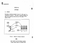
3.1
CONTACTS
The method of setting contacts by use of a shim qaqe is
illustrated in figure 2. The shim is inserted between the
base of the adjusting screw and top of the upper curved
contact spring.
INDIVIDUAL
ALUMINUM
CASTING
.
ADJUSTMENT~.
SCREW
\
==---------a=i~=====-
~~-
CONTACT
CONTACTS
Fiqure 2.
INSULATION
·
SHIM
/
=~r:~ -
NYLON
SPRINGS
X.H.
L
M
H
Method of Settinq Contacts
NOTE
Never insert the shim between contacts.
Contacts should never be adjusted when
a car wheel is positioned on the weigh
rail.
In addition to the standard contact setting instructions
listed below, each individual application drawinq includes
a detailed adjustment procedure.
Shim gage utilized in setting contacts should be similar to
"Lufkin Thickness Gage #126T". A small one-quarter inch
open end wrench should be used for individual screw adjustment.
3.1.1
Standard Contact Settinqs
To determine circuit continuity in the followinq adjustments,
an analyzer such as an ohmmeter, buzzer (or liqht) and battery
should be used.
Light Weight (L) - 14 to 35 Ton Car Loads
Connect analyzer between the white (common) and green (light
weight) wire leads in the junction box. Insert .015" shim
gage between the "L" adjustment screw and the long contact
spring (see figure 2).
5793, p. 6
UNION SWITCH & SIGNAL
Place the shim flush against the adjustment screw head. With
the shim inserted correctly, turn the "L" adjustment screw
until the circuit is just completed.
Medium Weight (M) - 35 to 52 Ton Car Loads
Connect analyzer between the white and black (medium weiaht)
wire leads in the junction box. Insert .040" shim aaqe
between the "M" adjustment screw and the loner contact sprinq.
Turn the "M" adjustment screw to just make the circuit.
Heavy Weight (H) - 52 to 110 Ton Car Loads
Connect analyzer between the white and red (heavy weiaht) wire
leads in the junction box. Insert .060" shim gaqe between
the "H" adjustment screw and the long contact spring. Turn
the "H" adjustment screw to just make the circuit.
Extra Heavy Weight (XH) - 110 Ton and Up Car Loads
Connect analyzer between the white and blue (extra heavy
weight) wire leads in the junction box. Insert .135" shim
gage between the "XH" adjustment screw and the long contact
spring. Turn the "XH" adjustment screw to just make the
circuit.
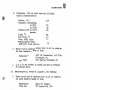
3.1.2
Five Weight Catagories
The Type IV Weigh Rail when shipped from the factory is
preadjusted for the standard four weiqht setup. In those
installations using a five weiqht system, the followina
procedure is to be followed.
The Automatic Light indicator (0-24 tons) is derived from
track occupancy.· The weigh rail provides the four remaininq
weight indications. The settings are different than for the
standard four weight system.
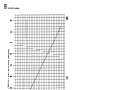
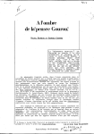
Shown in Fiqure 3 is a araph illustratina the relationship
between the contact gap settina versus the qross car weiqht.
Light Weight (L) 24 to 35 Ton Car Loads
Connect analyzer between the white (common) and green {liaht
weight) wire leads in the junction box. Insert .029" shim
gage between the "L" adjustment screw and the long contact
spring (see figure 2). Place the shim flush aqainst the
adjustment screw head. With the shim inserted correctly,
turn the "L" adjustment screw until the circuit is just
completed.
5793, p. 7
m
UNION SWITCH & SIGNAL
.180
I/
/
.160
/
~'I'
v
.140
I/
/
z
--
~
u,
w
~ .120
v
,..
/
CJ
~
...w
/
.100
i,
u,
a.
c(
I/
CJ .080
...
/
~
z
0
v
v
~
/
0
0
~v
/
en
z
~/
.060
.
I/
v
v
~
"'
/
/'
.040
,/
/
/
/
.020
.ooo
/
v
v
~"
0
Figure 3.
5793, p. 8
20
40
60
80
100
GROSS CAR WEIGHT (TONS)
Contact Setting for Various Car Weights
120
UNION SWITCH & SIGNAL
ffi
Medium Weight (M) - 35 to 55 Ton Car Loads
Connect analyzer between the white and black (medium weiqht)
wire leads in the junction box. Insert • 043'' shim qaqe between
the "M" adjustment screw and the long contact sprinq. Turn
the "M" adjustment screw to just make the circuit.
Heavy Weight (H) - 55 to 90 Ton Car Loads
Connect analyzer between the white and red (heavy weiqht} wire
leads in the junction box. Insert .068" shim qaqe between
the "H" adjustment screw and the long contact sprinq. Turn
the "H" adjustment screw -to just make the circuit.
Extra Heavy Weight (XH} - 90 Ton and Up Car Loads
Connect analyzer between the white and blue (extra heavy
weight) wire leads in the junction box. Insert .110" shim qage
between the "XH" adjustment screw and the long contact sprinq.
Turn the "XH" adjustment screw to just make the circuit.
3.1.3
Master Adjustment Screw
Under normal conditions the master adjustment screw (see Dwq.
F451059-Sh. 02), which is set at the factory, need not be
adjusted. Should there be any difficultv in obtaininq desired
settings of the individual adjustment screws due to extreme
wear of component parts, rail set, etc., a moderate chanqe
in the master adjustment screw setting will return the
individual adjustment screws to their oriqinal settinqs.
Any alteration of the master adjustment screw settinq will
effect all four individual screw settinqs. A clockwise
rotation of the master.adjustment screw will cause a narrowina
(closing) of individual screw contacts while a counterclockwise rotation will cause a wideninq (openinq) of
individual contacts.
A small 7/16" open end wrench should be used for master
screw adjustments.
3.1.4
External Parts
Weigh rail side plate bolts should be checked periodically
(refer to Dwg. F451059-Sh. 02). These bolts should be tiqht
to prevent entrance of foreign matter into the operating
mechanism.
·
The controller box cover should be held tiqhtly in place
insuring compression of the internal qasket.
5793, p. 9
m
UNION SWITCH & SIGNAL
SECTION IV
LUBRICATION
Periodic lubrication of the weigh rail is essential to proner
operation. The weigh rail should be lubricated (at least
once a year), dependinq upon amount of service. The weiqh
rail need not be removed from the track for lubrication. To
prevent damage to components, exercise care in following
the disassembly procedure outlined below.
4.1
WEIGH RAIL DISASSEMBLY (REFER TO.DWG. F451059-SH. 02)
1.
Place the heater switch, at the junction box, to the
OFF position.
2.
Remove the ramp (item 3, Dwg. F452002-SH. 06 or Sh. 22).
3.
Clean both sides of the rail section above and around
the side plates, removing all dirt, grease and corrosion.
Clean the side plates, the top of the rail, etc., to
prevent foreign matter from enterinq the mechanism during
disassembly.
4.
Remove the controller box cover (item 4, Dwg. F451059-Sh. 2).
5.
Measure and record contact gaps (L, M, H, and XH). The
contact settings will be checked (and may be duplicated
if necessary) before the rail is returned to service.
6.
Replace the controller box cover.
7.
Remove the bolts and washers (items 21 and 24) holdinq
the back plate (item 3) to the rail section.
8.
Remove the back plate.
9.
Remove the muslin bag (item 22), containinq VPI crystals
from the slot. If necessary refill with two ounces of
crystals, Specification M-7 450-1.
(See specification
tabulation in "Lubricant Specification" Section).
10.
4.2
1.
Remove the bolts and washers (item 21 and 24) holding
front plate (item 2) to the rail section.
WEIGH RAIL LUBRICATION
The following materials are required for proper
lubrication of the weigh rail.
a. Two (2) a-rings, UJ67134 (17" inner diameter x .139"
cross-section).
5793, p. 10
UNION SWITCH & SIGNAL
b.
0-ring Grease, UJ41593, Specification M-7680-2.*
c.
No-Rust Grease #1, UA41229.*
d.
Instrument Oil UA41099 or liqhtweight hiqh grade
non-gumming machine oil.
·
e.
VPI (vapor phase inhibitor) crystals, UA41087,
Specification M-7450-1.*
2.
The procedure for lubricating the weigh rail is as
follows:
4.3
a.
Remov~ and discard side plate 0-rinqs (item 28).
b.
Using mineral spirits, remove all corrosive material
from the o-ring grooves, the interior side plate
surface and mating rail section surface and the slot.
Wipe dry with a clean lintless cloth.
c.
Apply liberal amounts of o-ring lubricant (UJ41593)
to the new 0-ring (UJ67134) and 0-ring grooves,
then install new 0-rings into the grooves.
d.
Coat the side plates with grease (UA41229).
e.
Apply a few drops of instrument oil (UA41099) to
primary lever bearinq Y (see fiqure 1).
WEIGH RAIL ASSEMBLY (REFER TO DW~. F451059-SH. 02)
1.
Replace back plate (item 3), bolts and washers.
2.
Replace muslin bag containing VPI crvstals in the space
between the end of the slot and retaining bracket
(item 13-).
3.
Using the dowel pin as a guide, replace the front
side plate.
4.
Replace the front plate, bolts and washers.
5.
Remove controller box cover and carefully clean
contacts with a relay contact file or fine emery cloth.
6.
Readjust contacts to agree with oriqinal settings if
necessary.
(See "Adjustments", A. Contacts).
7.
Replace the ramp.
* Specific information covering the above lubricants toqether
with approved eources of supply are listed in "Lubricant
Specifications" section following.
5793, p. 11
m
UNION SWITCH & SIGNAL
SECTION V
LUBRICANT SPECIFICATIONS
5.1
SPECIFICATION NO. M-7680-2 (UJ41593) - NO. 2 SILICONE
GREASE
1.
This grease must conform to MIL-L-4343A.
2.
This grease can be obtained from either u.s.&s. by
ordering the above commodity nun:iJJer or from:
Manufacturer:
Trade Name:
3.
A satisfactory source of supply for this grease in
Canada is:
Manufacturer:
Trade Name:
5.2
1.
This grease can be obtained from either u.s.&s. by
ordering the above commodity number or from:
Trade Name:
5.3
1.
Dow Corning Silicone,LTD.
Toronto, Canada
No. 55 Pneumatic Grease
SPECIFICATION UA41229, RUST PREVENTIVE GREASE
Manufacturer:
2.
Dow Corning Corporation
No. 55 Pneumatic Grease
Gulf Oil Corporation, Gulf Bldq.
Pittsburqh, Pennsylvania
Gulf No-Rust, No. 3
This grease is not stocked in Canada and must be
obtained as indicated above.
SPECIFICATION M-7611-01 (UA41099), INSTRUMENT OIL
The above oil must conform to the followinq
specifications.
a.
5793, p. 12
General Composition - This specification covers
a high quality synthetic lubricating oil suitable
for clock-work mechanisms and delicate instruments
in a temperature range of from 30°F to 150°F. It
is oxidation resistant, has low volatility and
does not creep or spread.
UNION SWITCH & SIGNAL
b.
Properties - The oil shall have the following
typical characteristics:
Gravity, A.P.I
Viscosity, Centistokes
at 320F
at l00°F
Viscosity SUV at l00°F,
seconds
Flash, °F
Pour Point, °F
Color, ASTM, Union
Neutralization Value
ASTM D974, Total Acid No.
2.- This oil can be obtained either from
the above commodity number or from:
Manufacturer:
Trade Name:
3.
5.4
1.
270
28
132
405
-40
1.0
.01
u.s.&s. by
orderinq
Gulf Oil Corporation, ~ulf Bldq.
Pittsburqh, Pa.
Gulf Special Instrument Oil
This oil is not stocked in Canada and must be obtained
as indicated above.
SPECIFICATION NO. M-7450-01 (UA41097), VPI CRYSTALS
These crystals may be obtained from
the above commodity number or from:
Manufacturer:
Trade Name:
2.
21.6
u.s.&s.
by orderinq
Shell Oil Company
VPI Crystals No. 260
A satisfactory source of supply for these crystals
in Canada is:
Manufacturer:
Trade Name:
Shell Oil Company, Toronto,
Canada
VPI Crystals, No. 260
5793, p. 13
m
UNION SWITCH & SIGNAL
SECTION VI
GENERAL MAINTENANCE INSTRUCTIONS
6.1
WEIGH RAIL
1.
6.2
The rail mounting (in track) should be checked
periodically. The center gap of 16 inches must be
maintained. The weigh rail should be held tightly
to the ties and foundation so that there is no
"pumping". Side pla.te bolts s~ould be tight.
CONTACTS
1.· Contacts should be cleaned and settings checked at least
every sixty days.
6. 3
HEATER
1.
The heater should be turned on at temperatures of 40°F
or lower. During freezing weather conditions the
heater should be operated continuously.
2.
The application of external heat such as a torch
to the weigh rail or controller box is not recommended.
Application of external heat hastens the loss of
lubricant and in extreme cases can damage internal
wiring.
5793, p. 14
UNION SWITCH & SIGNAL
ffi
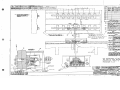
APPENDICES
5793, p. 15
UNION SWITCH & SIGNAL
--,--::---~-
-----~ --~-- -
.... hF.
._
-····
......... ,~
-a !01
-02G!
-
--
I
--<205
-0207
1--
-0208
--
............ ~
I.M377S31
REJIAJiKS
__. ....
8
o
....
1,;;!Jf.AAX
6
6
111432333
u.on531
W1TH
,52002-06()g_
111.hTH
WITHOOT
SEE NOTE G
WITHOOT
SEE NOTE G
UM34~694
IJM3847f.Z.
8
OIJL'()
11~,·z
111nMot11'
.SIEFIX NO'S. MIIIK£0 ~ARE FOR CIWVERTING
EXISTll«l WEIGH RAILS FRO! TlllEE-IIEIGHT TO
FOUR-IOiHT C~IFICATl<W
NOTE
..
- INSPECT & TEST PER SPEC. EU5005
NOTE A -
:1: ~m:!
~g;iAmM,a,f-hARTs.
NDTE 8 • BEFORE ASSIMILYf COAT BACK OF FR<WT & BACK PLATES.
ITEMS 2 ANO 3 W Tli A HEAVY CMTlll6,«
ITEM 30. OR ITEMe.J
•Y
NDTE
c - m ~ R F . J k ~ i , g JMRtfppttlEf~~~
NOTE
o-
SPECIAL IIISTRIMEHT 9IL (QA41im) AT BEARING& 11
NOTE E i«ITE
lli&~ !Pllt1M'~1«iarcrrro~ -·LA CORO
m
t/Ji~(i
ASSEMILl~iT MINGS, ITEM 28 OR ITEM[)
ITEM Of 0-RING GREASE M-76S0-2,
F• y~'YJ,fclhiij!Mf·
..,...
1~~01iE1rJ~\{M11\!1;POR
CLOSED ANO IIISER!E6 lt(!O SPACE INllCAfEO BY ARRON.
NDTE G • MIST
l~CT
PER !U5005
R Ail:'u\1MENT
SCREW & WEIGHT ADJUSTMENT SC~EWS
TO B strfNPPROx. POSl!IOIIS.
For Adjustment of Rail
for Use in Five Weight
Categories, Refer to
Paragraph 3.1.2
F11, R•'- o,,,!I
t Mei.e.s .. J."
1.112 .,:-.: . ' . cttf'~~;~--,--c-~·~·
V11w "YV1t.w SNOWING Jo1HT BAil 'Dtt.tLl.lHe
G~EEN LEAD~G (I)
·.
44
44
\0
1
i
i
l.J.
Yre
4.
WS:.16M Rtht,,. $ac.TtON(W1T1"' Z.4V,M ....'T . . .) ~ T
TYPE + lfEIGI! RAIL 5_ECTIOII_ _JWITH Ii V. HEii~
VIEll
LOOKING IN!O CCIITlOI. -WllH COVFR RfM>IED
"
--·--'._~
TERIAL KIT, FR<WT PLATE
_J14V.HTR.,
tR<WT PLATE ASSEMBLY WITli CONTROLLER, 14V HEATER, ETC.)
,MATERIAL KIT, FROO PLATE
FR<WT PLATE ASSEMBLY WITh CONTROLLER, 24V, HEATER, ETC.)
TYPE 4 WEIG/t R'IL SECTl<W
(WITH 14V. HEATER)
l'fPE 4 WEIGH RAIL SECTIIW
(!IT!i 24 V. HEATER
OESCR I PT l<W
EB
UNION SWITCH & SIGNAL
WEIGH RA
PC. NO.
COl'I..
c,51059
SH.
I
TR
24-VOLT
14-VOLT
CLI _ ___ .,,.,
H.01..11.s·z·
REMA-.K.S
Wt-rH(~~)
w,rH(s:!..... ) 0090250
24•VOLT
SEii: J,JoTE"'G"
UJJ390.207
24-WLT
SEE NOTE°(;.•
N3,0Z07
UR4'?i5i2.2
Rlt-~GBI
;.
i
·1
.j
~
I'
J
,
•
I
~
;
I
_1r-·1i
. ,
;2
/2_
·,,:j
I~
,
t
I
,
. ...
I
I
I
.L~_JI2).L__Jc;_]_
j
.
/2
11
!
.
I
I ..__Jr·,,
I I
11
bl[lLJ
r== · ------ - --- ·-= .:)
1
I
f,
i
,
.
:
.
;•
,
,
-
u.tl2&183
tlX432351-00I
I(
.
·r-! II .f
I
i~~
•
,·
\
I
!
_J•
'1
'-
!
•
,
•
8
t--.......8 _.:i
1
I
•A·'
1·
·1
•
•
•
.I
j
i
q
j- l
+
:
I
'
•
1'
2.7
I
~·~=1j""-'W
~
-
L ·
.
J
I
_
I
r - -----
..-L-- -
4
I
~
I
·-
f1' (FOR
I
_-.
L------
l"f~fWll\8~ f~ ~lfc.l:U.Jff ~liJF~L~~~EIGH
Nott G
RAIL CALIBRATIOO.
~
,.
L'"
14 TO 3~TON
JNSERT
. • Ol5_~E(SHIM)
c
eE!W~PtTHE
1
l~~~
CAR LOADS
'&y C:USTOMII.R..
COIMCT BUZZER AM> BATTERY TO THE WHITE A11D
.BLACK WIRES IN .AN:TIOO BOX.
r ;
i
• ·1
-.
-
. --- 1
• M•
(isTo52TOO
L
I
• ~---
•
~-=J.
_j
i_
·
T
"'T
-....
I
I
·
'<I\>
...__ ---,
!!!
~t.---,
' ;
r - - ------ · - - -·. - - - - 1
I
~
INSTALL RAIL & RAMP IN TRACK AS SHOIN. SPOT HEAVY CAR
8
r.Gw:~..u~~,U\ifME~M~~Tro,.c~~M 0o~
PU.CE 00 POST•
•
,ECT BUZZER AM) BATTERY TO THE WHITE
AM> GREEN WIRES IN JlliCTIOO BOX.
I- -
~il
.
I i
.
LJ
NOTE F -
Y,Utti.tt RAH. '&y CuS'TOMe.111. T'o S.u,T
l'ltn..L.U•~ 1..a .J'ou,JT '&~tt. SuPP\.\'I.D
:1
u.s.&S.
NOTE C - VICINITY
TRACK GAGEOFTOBE
WIDENED
1/4soTOGUARD
1/2 INCH
WEIGHING
DEVICE
RAILSINWILL
BE EFFECTIVE IN PREVENTING WHEEL FLANGE !ATERAL
PRESSURE 00 WEIGH RAI~.
NOTE D - SPACER BLOCKS SHOULD BE WELDED TO TIE PU.TES BEFOlE
INSTALLING WEIGH RAIL. SEE SECTIOO A-A.
NOTE E - BOTTCJ.1 OF JlliCTION BOX FLUSH WITH TOP OF TIE.
NOTE. ..G·- Hoi.e.s'Z7ltU "DltlLLED IN £.l't.CH E.~o Of'
ff
PLATE, TIE(! X 5 X 6FT, 5-1/4
GUARD RAIL TO BE CENTERED OPPOSITE CENTER LINE OF
WEIGHING DEVICE. STRAIGHT PORTIOO PREFERRED AS
LOOG AS WEIGH RAIL {7 FT .-4) BUT IN Alfi CASE NOT
LESS THAN 66 INCHES.
RE.F. OliLY)
..
1
a-
'DR11.1..(41HoLE.s 1..i R1u,•P(l:Tii.J1113)
®
I
'
•
f
NOTE
ITT .
.
1 r>mt; ·r,rn x s x ,
2
NOTE A - PARTS SHOIN IN FULL LINES FURNISHED BY
To 'l>UIT C.oN1'1TION'ii
IN TMI<. Fll!LO
•
I
I
2
J ::;
Lcc .. Tr.o
(111I
_J_'
L
. . ..
.
·-1,-..-.--- - - - · - - - ·
,
~
CONTACT 51'111"'5
1--
,
RAMP
BLOCK SPACER
BLOCK SPACER
OOTLET
(
/.
•
'-'
; ___ -- 7,t''f,'
~
- -if,-
GI
G--1
I
I
, •
• It - •
•.
•
.
I:"'~ __l_ _ _L_
I
-·t,f' W•19hu19 .Dwtv,t:ezfi Co,,,~~,•fe r;~ndar,o
__ L __L -
,·
,
,,
+----. - - - - .
+-
•
6
9
5
5
2
FURNISH THE FOLLCWING ITEMS FOl EACH
RETARDER YARD INSTALLATIOO
Lt1326557
I A2586 I TSSI WRENCH
21
1'1]s1'I
1·
I'I1 \.,.~.) •
•
~
I
r- - -----;-___:_::__-;------:--=-:..--=-===i'
r. •=3j,
n-r-rr-r:1
1-_j
.
,.
.
.
I
11
r- -::----- · . I
~. j ! -- ! ;_. _i ! ! - !
__L
I ,(
-$,----.I
L' .
•
,
I
-..,----r
.
.
.
i( '
("'\
!•
I. I -+
I- - -.11-. -
I
.
02
~_.1( __ 6 LAG
j )
·,_.
I
I
I
.--- ~ - - - .- - - - -
-~-·
STANOAR' TIES CJ! P,\WS'I'
•
. i !)j
i_.-=r- [CJ!
j
'
OESCR IPTIOO
RAIL •EIGH
BOX JlliCTION
SH.
THE FOLLCWING ITEMS ARE FOR REFERENCE OOLY
lM'.376133
17913
I 52 I BOLT. l'OtmAnoo
UJ47509
!WASHER, I STL. PLATE(CAD. PL.)
STL. HEX. (CAO. PL.)
;'2-1
u····:
•
sm,orEF I
I
I
jsf£'N07E ,B
f IIa I.I,-·1.II ·-· I:r·11l·-'
7J
~--,ci,
·J
,
r
r"'\
J
,
NOTE1
~EIGH
A~BI
ROAD
:;
--.- -
-~-
(sEE ntll)
lM3264B2
-·1°1JLJi
iJur
u:1~J=:4ru1-rFT·{·iu:~T-lil
lI.
I ·' I ! ' ' j
I ! '. j.
I
~/%1 ~ ~
r7{-l 1 ~
~"~l I I ; ~
_ _ _1 __
!!
+.
__J_
-,
DWG.
F451059
066316
FBOOIJ
C50002
C50002
066316
0
i
ll- -1.::--
I
1
,l: 11 __ j~~I
-L.
r~
.I ~·UIiEl
L
·~ir~·~;:~J?~f·~ _" :l1iw;'
Ull3'4'-.SG81
""
PC, NO.
{SEE TAB)
ISEE TAB
i
r--- ·
. ---,
!
.
I
i .
._.__j
c:JJ
)
(r
±'
~
,I
J
CAR LOADSC!HIECT BUZZER ANO BATTERY TO IH£ WHITE AM)
RED WIRES IN JlliCTIOO BOX.
•
NSERT ,..o,gp GAGE (SHIMl BElllEEN THE
.. H
AOJUSIM:NT SCREW ANO THE OiG C<M'ACT
!52 TO 110 TOO PRING. TURN THE AOJUSTMEfd SCREW TO
CAR LOADS
T MAKE THE CIRCUIT,
'
~OIMCT BUZZER AM> BATTERY TO IH£ WHITE
ANO BLUE WIRES IN Jt.NCTIOO BOX,
I
,
_--- - .
--- .
·~RT .135 GAGE
~ml BETWEEN THE
..,,,
110-;gr oo ~oor:8Fs=.~URN THET~~NT
CAR LOSOS SCREW TO ,U;T MAKE THE CIRCUIT,
~
1·
~11-S.~"·
{\J
i1
j
L
0 .g
00
m:Z:
J
('J.
For Adjustment of R~il
for Use in Five Weight
Categories, Refer to
Paragraph 3 .1. 2
i
..tdl
""
-:
l~
I _..r~" ~
X.45ZOOZ-K04
/ 'wc·,{/Zll/1//;
,
.
'
.., .L BET•EtN
I_
~
"3zSPACER BLOCKS
I i,,k1&,I RAIL_, ,..,OUN rE"D ON CON'CAC1'£
F'OchlDATIOH(U~NG ZfV. Htll~
!lQ4!;2002-0601
f ~EIGH_RAIL, M(l(P.ITtO ON CONCRETE FOlNlATIOO {USING 24 V. HEATER)
PARI NlMlER _I_
OESCRIPTIOO
___.J
BEFD!lE INSTALLING
MEiio~ RAIL (SEE NOTE D)
2
1
.'!, •
.e
..... i.:r,,:~~=~t"'">..::t-
·-------
,- d '% "'
-iI
·----11'-=----- ..
----i
I/4 FI ~T WELD (BOTH ENOS)
4 :; In% .. '(
~~ r;!.Eo::J::::·
Moo.aTE't> ow Co,.ctt.E.TE f'ouun"T1ow(osuac.24V.H~~~~"'o."'
WElllll-RA!I., t.«lltlTED <Jl_cONCRETE ~TIOO (USIMl 14 v. HEAJER)
~El~H RA1~ 1
1 :1;J;
!ti~~~:1---e::~~:;.:,:
:e;;?:; 11:
! Jr:
,i·~;. ... r,·
~if!~~if1;E~·.;·;·
i_ •
~!: ! ~?.~:;::~~!',
!it. f.'.,
,• w
UNION
-----
~ -!:..-.i-
----~--------- - l .
. __________,._ -
SW.'J..!;.,H.. a
SIGNAL
--::::~~!!':y~~.~
1t "-
l"'k1h'31:"Q~ ..
·•
m
01(1/irl,.,RL APPltOV~L-
I
Jfld,a:-ll-17-U
UNION SWITCH & SIGNAL
PC. NO.
CO,f>L.
I
j F451059
_j 511..,j HEATER
24-VOLT
14-VOLT
'(1"45200%·Z2C3 lrJA1..SIO"-atc8lo2
-
.,Q«;flll'f 6UA tt}
wrrr.H RAii Col
I 24·VoLT
Hol.ll$"Z"
, _. . h
w1TH (As s"'°"'") 0090207
f#/ITH (AS"'°11111) 0090250
5&.E NOT& ..6.
U>l390207
3
RA""P
FROOl'°!J
s...
6
6
UR349t.8t
9
ll~g
Ult349C.81
UA4357%~
'
11 1
le
'
~l
ltEMAltlC.S
l'Dlwt."L"
..
) Fut•- MlilO"' F•-. W4W R...... o 1'e.U.w.11- Y•.
/e
I
~
FtR5T MAO• Foa. Tllr, p Ry.C..LAWC:At,Talll'iD.
.~-:
Im
I
if~~;
I•
I
---1
u.-
,F..
•
I-
ii
~ - --(',-
=========t=::-~--:'::::·-=====-:-:~=-==.
- ----F-r-,j
-
r-- --------- -
•
p
__
r
~~==-'--'=.::..:-_=!:=_
-----
II
I c:c::.
"
•,
e 1r
L..J
____~=:'i
- 11
b~
n
11 -
i!r-d
!I
b.-..di •
-
.•
-- -1
---.:::::::.J
..
IL
I
~
"-'.._=11
i.k-...:::5
{
.
_ •
I:>
~
0\
l
b=.
II
F"
i
r-:-; r·, ·H _l!__tl __.___,
a
- <d=- ____
'11
t
'
. .
'I
:
(
L
-
,
--r .
,.
- - - - -- -
-·,----
-!
.:..=..:...._
·
-
J'
- - ~ -,.,-__________
-
.]
I
I
- -----
/.::
·1
- - - •"<- ·
-----
TE SLAB
0
J&~~l~LV1st&fflav£AN)IMY11£
TO AGREE WITH LOCAL BEO CINllllONS.
J
~
TO 1/2 11«:H IN
50 GUARD RA I LS
INi WHEEL FLANiE
)L,
• ,.
I
_:..l
------------:-:;:,:t-------------
We19hm9 .I)ev,c• ( Concrefe ('<>undahon
,;f
~
'----lfJlT:r~~H~
r.GE!J
C...
t
r~GHl~
--:..:..=i
• ;•
6
NOTE O - SPACER BLOCKS SHOULD BE WELOEO TO TIE PLATES
BEFORE INSTALLINi WEIGH RAIL. SEE SECTION A-A.
NOTE E - BOTT!J,! OF JIH:TION BOX FLUSH WITH TOP OF TIE.
:,irr:~~tG~~'LgLr~v,l:.'RA'L 0 c
Mo"l'ie,.··
~
"'.I) R •LI.
Loc.AiT!,.l),
.•
Z
~-
..---~---~-7rl~-l-------~-~~-i
~---~-+-----·ff-~---...i
t,to1..1i.1> .. C." lo Bft
'Dtt.u.. i..e.l>
tN
E.l\t..t END
,~
CAR LOADS
13,y CosTo...,aR..
1t11~.:ossmY
1F---~- _ ---.~~~~
C(M£CT BUZZER ANO BATTERY TO THE WHITE ANO BLACK
!'IRES IN JtH:TION BOX.
---=-=~
--===f·
- - - - - - - -,~..,.J
L
.-
i--1
I'
'--~
c_:J
11
l4-TOLlS TCJ.4
WE.tGt,,\ R.lh\.. 'Sy CusTe>MltR. TO Su,,.
J:>R.ll-'-lNG lN J"ou,.aT "BAii.. Su1"P1..1&1)
J
r·-
~
i.,T~LL~&«it,~.JrLT~cMM't~ rJm~ri:R,
ANOTIGHTENNUTS. IMCABLE INTOJIH:TIONBOX,
BUT oJO NOT PLACE ctl POST.
("t) Hoc.E.S IN R "'MP (1:'TE:"\ 3)
TO ~ I T CotJl)1"';IOtJS
IN THE F'IEI.O
.
u.s.&S.
NOTE B - WJ;O RAIL TO BE CENTEREO OPFOSITE CENTER lltiE OF
.~,~~C[lllswifl!.~B1W1ll:~E~ ~T
LESS Ttl<N 66 INCHES,
F-r~,-,::_~
II
.
Ir----"=_
r
- - -==-----.
,I
~i
--===-=11'1] - n -1i
11
NOTE A - PARTS 5IIO'IN IN FULL LltiES FURNISHEO 6Y
·-.
------,
I
/1
r-----I
<:~~ff:
"M"
3STO 5"Z. TON
CAR LQl.05
5. TURN THE
TO JUST MIIKE THE
TltE
"HM
5'2.TO 110 TON
CAR L0,.05
--·---.:
i
-·-"· ~-J
CAUTION
For Adjustment of Rail
for Use in Five Weight
Categories, Refer to
Paragraph 3.1.2
~!!;.
UX45200Z-2203
U0452_CIQ?_-ZZ02
U0452002-ZZOI
REV
PART NlMI_ER
~--p,..~_ _ _
__,-,;:-,_.,---:-----:-____:_----,;;i~·~--;.s~
C~~~~~~~=::~F...E:::..::-.::2.:::.:::j;~-:Jriij
- -· . -~
... .;:;;-.::::--,=.::~=·12
-
lSO.LE. -
'"· - ' " "
-,.,.=--
~
..~-l
~ l t , . . f f - L Y... ~
uN10N. iw1TcH
a
sidklt'i
122'1 I
~--'.
EB
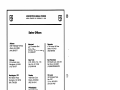
UNION SWITCH & SIGNAL DIVISION
AMERICAN STANDARD INC. I SWISSVALE, PA 15218
Sales Offices
2409 Treelodge Parkway
Atlanta, GA 30338
(404) 399-3577
Montreal
1115 Dorchester Blvd.
Suite 1003
Montreal, PO, Canada H3B2J2
(514) 866-3677
Roanoke
4718 Hickory Hill Drive
Salem, VA 24153
(703) 989-8400
Chicago
216 Lancaster Lane
Bolingbrook, IL 60439
(312) 759-3577
New York
40 W. 40th St., Rm. 1105
New York, NY 10018
(212) 840-5438
San Francisco
903 Sneath Lane, Suite 230
San Bruno, CA 94066
(415)588-6788/588-6789
Huntington, WV
Omaha
6122 Gideon Road
Huntington, WV 25705
(304) 736-2629
16326 Oak Circle
Omaha, NE 68130
(402) 334-1516
St. Louis
500 Northwest Plaza
Box 1267
St. Ann, MO 63074
(314) 291-7400
Atlanta
Phlladelphla
Jacksonville
P.O. Box 8609
Jacksonville, FL 32211
(904) 724-2607
Honeywell Center
111 Presidential Blvd.
Suite 206
Bala Cynwyd, PA 19004
(215) 667-7072
Pittsburgh
1789 Braddock Avenue
Pittsburgh, PA 15218
(412) 273-4300
Mall all orders to:
Order Entry Department
Union Switch & Signal Division
American Standard Inc
Swissvale, PA 15218
St. Paul
402 McColl Building
5th and Jackson
St. Paul, MN 55101
(612) 222-7562