1
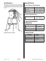
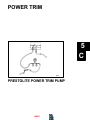
POWER TRIM
5
C
26345
PRESTOLITE POWER TRIM PUMP
INDEX
Table of Contents
Page
Identification . . . . . . . . . . . . . . . . . . . . . . . . . . . . . 5C-1
Specifications . . . . . . . . . . . . . . . . . . . . . . . . . . . . 5C-1
Valve Pressure Specifications . . . . . . . . . . . 5C-1
Electrical Specifications . . . . . . . . . . . . . . . . 5C-1
Lubricants/Sealers/Adhesives . . . . . . . . . . . . . . 5C-1
Special Tools . . . . . . . . . . . . . . . . . . . . . . . . . . . . 5C-1
Description . . . . . . . . . . . . . . . . . . . . . . . . . . . . . . 5C-2
Thermal Circuit Breaker Operation . . . . . . . . . 5C-2
Manual Release Valve Operation . . . . . . . . . . . 5C-2
Maintaining Power Trim Pump Oil Level . . . . . 5C-2
Air Bleeding Power Trim System . . . . . . . . . . . 5C-3
Bleeding OUT/UP Trim Circuit . . . . . . . . . . . 5C-3
Bleeding IN/DOWN Trim Circuit . . . . . . . . . 5C-3
Testing Power Trim Pump . . . . . . . . . . . . . . . . . 5C-4
Connecting Test Gauge . . . . . . . . . . . . . . . . 5C-4
Internal Restriction Test . . . . . . . . . . . . . . . . 5C-5
OUT/UP Pressure Test . . . . . . . . . . . . . . . . . 5C-5
IN/DOWN Pressure Test . . . . . . . . . . . . . . . . 5C-5
Trim Cylinder Internal Leak Test . . . . . . . . . . . . 5C-5
Trim Cylinder Shock Piston Test . . . . . . . . . . . . 5C-7
Motor and Electrical Bench Tests . . . . . . . . . . . 5C-7
Trim Pump Motor Test (In Boat) . . . . . . . . . 5C-7
Trim Pump Motor Test (Out of Boat) . . . . . . 5C-8
Solenoid Test (Pump in Boat) . . . . . . . . . . . 5C-9
Solenoid Test (Pump Out of Boat) . . . . . . . 5C-10
110 Amp Fuse Test (Pump in Boat) . . . . . 5C-11
110 Amp Fuse Test
(Pump Out of Boat) . . . . . . . . . . . . . . . . . . 5C-12
20 Amp Fuse Test . . . . . . . . . . . . . . . . . . . . 5C-12
5C-0 – PRESTOLITE POWER TRIM PUMP
INDEX
Page
Trim Pump Removal . . . . . . . . . . . . . . . . . . . . . 5C-13
Hydraulic Repair . . . . . . . . . . . . . . . . . . . . . . . . 5C-13
Manual Release Valve Replacement . . . . 5C-13
Disassembly . . . . . . . . . . . . . . . . . . . . . . . . . 5C-13
Valve Body and Gear Assembly . . . . . . . . 5C-14
Motor Repair . . . . . . . . . . . . . . . . . . . . . . . . . . . 5C-15
Disassembly . . . . . . . . . . . . . . . . . . . . . . . . . 5C-15
Armature Tests . . . . . . . . . . . . . . . . . . . . . . . 5C-17
Continuity Test . . . . . . . . . . . . . . . . . . . . . 5C-17
Test For Shorts . . . . . . . . . . . . . . . . . . . . 5C-17
Cleaning Commutator . . . . . . . . . . . . . . 5C-17
Field Test . . . . . . . . . . . . . . . . . . . . . . . . . . . . 5C-17
Test For Open Circuit . . . . . . . . . . . . . . . 5C-17
Test For Short In Field . . . . . . . . . . . . . . 5C-18
Thermal Switch Test . . . . . . . . . . . . . . . . . . 5C-18
Continuity Test . . . . . . . . . . . . . . . . . . . . . 5C-18
Brush Lead Tests . . . . . . . . . . . . . . . . . . . . . 5C-18
Brush Replacement . . . . . . . . . . . . . . . . . . . 5C-19
Brush Replacement . . . . . . . . . . . . . . . . 5C-19
End Cap And Brush Assembly
Replacement . . . . . . . . . . . . . . . . . . . . . 5C-19
Reassembly . . . . . . . . . . . . . . . . . . . . . . . . . 5C-20
Trim Pump Installation . . . . . . . . . . . . . . . . . . . 5C-22
Wiring Diagram . . . . . . . . . . . . . . . . . . . . . . . . . 5C-23
90-12934--2 1097
Identification
Specifications
Some MerCruiser Sterndrives will be equipped with
a Prestolite Power Trim pump. This pump was used
interchangeably with the Oildyne pump for a period
of time.
Valve Pressure Specifications
Valve
Pressure
2200 - 2600 PSl
(15173 - 17932 kPa)
Up Circuit
400 - 600 PSl
(2759 - 4138 kPa)
Down Circuit
Electrical Specifications
Pump Amperage Draw
115 Amps at
2200 - 2600 PSl
(15173 - 17932 kPa)
Lubricants/Sealers/
Adhesives
Description
Part No.
Power Trim and Steering
Fluid
92-90100A12
2-4-C Marine Lubricant
92-825407A2
Liquid Neoprene
92-25711-2
50524
Special Tools
Prestolite Power Trim Pump
Description
90-12934--2 1097
INDEX
Part No.
Test Gauge Kit
91-52915A6
Multi-Meter
91-99750
Torque Wrench (lb. ft.)
91-36210
Torque Wrench (lb. in.)
91-66274
Jumper Wire
Obtain Locally
PRESTOLITE POWER TRIM PUMP - 5C-1
Description
The Prestolite Power Trim Pump has internal valving
that eliminates the need for an external reverse lock,
as was required in the past. The pump generates a
higher volume of fluid, but at a lower pressure than
previous Prestolite pumps. This, in conjunction with
large I.D. hydraulic hoses (gimbal housing to pump)
and larger I.D. trim cylinders, should allow the drive
unit to “kick-up” easier if an underwater object is
struck.
! CAUTION
Due to differences in internal valving, the new
Prestolite trim pump cannot be used to replace
an earlier Prestolite pump, or vice-versa. Use of
incorrect pump will affect trim operation and may
cause damage to trim system.
The pump motor is protected from overheating by an
internal circuit breaker (on commutator end plate),
that interrupts the current flow through the field windings in the event of an overheating condition. Electrical current overload protection is provided to the
pump by a 110 amp fuse. Pump also is fitted with a
20 amp in-line fuse, which serves to protect the trim
control and harness from an overload.
Maintaining Power Trim
Pump Oil Level
! CAUTION
Vent screw MUST BE backed out two (2) full turns
(after bottoming out) to vent pump reservoir.
FAILURE TO BACK SCREW OUT COULD RESULT IN DAMAGE TO PUMP.
IMPORTANT: Check oil level with sterndrive unit
in the full down position.
IMPORTANT: SAE 10W-30 or 10W-40 engine oil
can be used in system, if Quicksilver Power Trim
and Steering Fluid is not available.
1. Place drive unit in the full IN/DOWN position.
2. Remove “Fill” screw from pump. Oil level should
be up to bottom of the threads in “Fill” screw hole.
If necessary, add Quicksilver Power Trim and
Steering Fluid or SAE 10W-30 or 10W-40 motor
oil (through “Fill” screw hole).
NOTE: In tropical areas, single viscosity SAE 30 motor oil can be used.
Thermal Circuit Breaker
Operation
If the IN/DOWN or “Trailer” switch is kept depressed
after drive unit reaches its end of travel, a thermal
circuit breaker will open to prevent pump motor from
overheating and pump motor will stop. Release
switch(es) as soon as drive unit reaches end of
travel, to prevent this from happening. If circuit
breaker should open, allow motor to cool down and
circuit breaker will automatically reset.
Manual Release Valve
Operation
! WARNING
Before loosening manual release valve, make
sure all persons are clear of sterndrive unit.
In case of a Power Trim system malfunction, the
sterndrive unit can be raised and lowered manually
by
turning
the
manual
release
valve
counterclockwise approximately 3 turns and moving
drive unit to desired position by hand. After drive unit
has been placed in the desired position, close valve
COMPLETELY. Power Trim system will not function
properly, unless valve is completely closed.
5C-2 – PRESTOLITE POWER TRIM PUMP
INDEX
50524
a - Fill Screw
b - Vent Screw
c - Manual Release Valve
3. Raise and lower drive unit 6 to 10 times to purge
any air from system; then, recheck oil level (with
drive unit fully IN/DOWN) and add oil if
necessary.
90-12934--2 1097
Air Bleeding Power Trim
System
Bleeding IN/DOWN Trim Circuit
The power Trim System will purge itself of a small
amount of air by raising and lowering the drive unit
several times. However, if a rebuilt trim cylinder is
being installed (which has not been filled with oil), the
following bleeding procedure should be used to
remove the air from the system.
2. Disconnect IN/DOWN hose from rear connection
on gimbal housing hydraulic connector. If both
cylinders were rebuilt, disconnect hoses from
both sides of hydraulic connector.
1. Ensure pump reservoir is filled to proper level.
3. Plug holes in hydraulic connector, using plug
(22-38609) or suitable device.
4. Direct end of trim hose(s) into container.
Bleeding OUT/UP Trim Circuit
1. Fill pump reservoir to proper level as explained
preceding. (Trim cylinder must be compressed).
2. Disconnect OUT/UP hose from front connection
on trim cylinder. If both cylinders were rebuilt, disconnect hoses from both cylinders.
3. Direct end of trim hose(s) into a container.
4. Run trim pump in the UP direction until a solid, airfree stream of fluid is expelled from hose(s). Reconnect hose(s) and tighten securely.
5. Refill trim pump to proper level.
5. Run trim pump in the UP direction until trim cylinders are fully extended.
6. Remove plug(s) from gimbal housing hydraulic
connector and momentarily run trim pump in the
IN/DOWN direction until a solid, air-free stream
of fluid is expelled from rear hole(s) in hydraulic
connector. Reconnect trim hose(s) and tighten
securely.
7. Lower drive unit to the full IN/DOWN position and
refill trim pump to proper level. Run trim system
IN/DOWN and OUT/UP several times and recheck fluid level.
22089
22089
a - OUT/UP Trim Hose
b - Front Connection on Trim Cylinder
90-12934--2 1097
INDEX
a - IN/DOWN Trim Hose
b - Hydraulic Connector
c - Plug (22-38609)
PRESTOLITE POWER TRIM PUMP - 5C-3
Testing Power Trim Pump
Connecting Test Gauge
1. Check trim pump oil level. Fill if necessary.
2. Place drive unit in the full IN/DOWN position.
3. Connect test gauge at the most convenient location (at pump or hydraulic connector).
22090
Gauge Connect to Hydraulic Connector
c - Caps
d - Plugs
26344
4. Open Valve “A” and “B” and run pump UP and
DOWN several times (to purge air).
Gauge Connected at Pump
a - Hydraulic Test Gauge 91-52915A6
b - Extension Hoses 91-52915A6
c - Fittings 22-77366
NOTE: Extension hoses MUST BE used to obtain accurate readings.
22126
a - Hydraulic Test Gauge (91-52915A6)
b - Gimbal Housing Hydraulic Connector
5C-4 – PRESTOLITE POWER TRIM PUMP
INDEX
90-12934--2 1097
Internal Restriction Test
Trim Cylinder Internal Leak
Test
1. Open valve “A” and “B.”
2. Run pump OUT/UP and IN/DOWN while observing gauge.
3. Replace adapter, if pressure is in excess of 200
psi (1379 kPa).
IMPORTANT: The following test assumes that
pump OUT/UP pressure is within specifications
as determined by performing “Power Trim Pump
Test.”
OUT/UP Pressure Test
1. Reconnect trim cylinder hoses (if removed in
previous test) as follows:
1. Leave Valve “A” open and close Valve “B.”
a. Remove plugs and caps.
2. Run pump OUT/UP while observing gauge.
Reading should be 2200 - 2600 psi (15173 17932 kPa). If not, replace valve body and gear
assembly.
b. Install UP hose to forward hole on hydraulic
connector. Tighten securely.
c. Install DOWN hose to aft hole on hydraulic
connector. Tighten securely.
3. Stop pumping OUT/UP. Pressure should not fall
below 1900 psi (13104 kPa). If it does, check for
and/or replace following:
•
External oil leaks
•
Valve Body and Gear Assembly
IN/DOWN Pressure Test
1. Close Valve “A” and open Valve “B.”
2. Run pump IN/DOWN while observing gauge.
Reading should be 400 - 600 psi (2759 - 4138 kPa).
If not, replace valve body and gear assembly.
3. Stop pumping IN/DOWN. Pressure should not
fall below 350 psi (2410 kPa). If it does, check for
and/or replace the following:
•
External oil leaks
•
Valve Body and Gear Assembly
90-12934--2 1097
INDEX
22090
a - UP Hose
b - DOWN Hose
c - Hydraulic Connector
PRESTOLITE POWER TRIM PUMP - 5C-5
2. Connect gauge at most convenient location.
3. Open Valve “A”and “B” and run pump OUT/UP
and IN/DOWN; several times (to purge air).
4. Run pump OUT/UP until trim cylinders are fully
extended; then, observe gauge while pumping.
Pressure should be 2200 - 2600 psi (15173 17932 kPa).
5. Stop pumping OUT/UP. Pressure should not fall
below 1900 psi (13104 kPa).
If readings are not within specifications, an internal trim cylinder leak is indicated. Use the following procedure to locate faulty cylinder.
a. If gauge is connected at pump, reconnect
gauge at gimbal housing hydraulic connector. Repeat Step 2; then, run pump in OUT/
UP direction until trim cylinder are fully extended.
b. Close Valve “B” on test gauge and repeat
Steps 3 and 4.
26345
Gauge Connected at Pump
a
b
c
d
e
-
If Readings Are Now Within Specifications: Trim
cylinder on the same side that test gauge is connected, is faulty.
If Readings Are Still Not Within Specifications:
Trim cylinder on the opposite side from where the test
gauge is connected, is faulty.
Hydraulic Test Gauge 91-52915A3
Fitting (22-77366)
Fittings (Supplied with Gauge)
Black Hydraulic Hose (From Gimbal Housing)
Gray Hydraulic Hose (From Gimbal Housing)
22126
Gauge Connected to Hydraulic Connector
a - Test Gauge
b - Coupling (Supplied with Gauge)
c - Front Hydraulic Connector Port
5C-6 – PRESTOLITE POWER TRIM PUMP
INDEX
90-12934--2 1097
Trim Cylinder Shock Piston
Test
If trim system checks out good, but drive unit will not
trim IN/DOWN, problem may be due to a leaky trim
cylinder shock piston. Use the following test to check
for this condition. Test gauge is not required.
1. Run pump in OUT/UP direction until trim cylinders are fully extended.
2. Prevent trim cylinder piston rods from retracting,
using a suitable device. Quicksilver Trailering Kit
works well for this purpose.
Motor and Electrical Bench
Tests
Trim Pump Motor Test (In Boat)
! WARNING
DO NOT perform this test near fIammables (or explosives), as a spark may occur when making
connections.
! WARNING
RemaIn clear of drive unit when performing power trim pump motor tests with pump in the boat
and hydraulic hoses connected.
1. OUT/UP Operation:
a. Connect a jumper wire between positive (+)
solenoid terminal and BLUE/WHITE motor
lead terminal.
b. Motor should run.
22562
a - Trailering Clip
3. Disconnect UP trim hose from trim cylinders.
50523
22089
a
b
c
d
-
OUT/UP Solenoid
POSITIVE Terminal (+)
BLUE/WHITE Motor Lead Terminal
Jumper Wire
a - UP Trim Hose
b - Front Connection
4. Run pump in IN/DOWN direction. If oil flows from
UP port on trim cylinder, shock piston is leaking
and must be replaced.
90-12934--2 1097
INDEX
PRESTOLITE POWER TRIM PUMP - 5C-7
2. IN/DOWN Operation:
3. OUT/UP Operation:
a. Connect a jumper wire between positive (+)
solenoid terminal and GREEN/WHITE motor
lead terminal.
b. Motor should run.
a. Connect a 12 volt positive (+) supply lead to
BLUE/WHITE motor lead terminal.
b. Connect the negative (-) supply lead to a
good ground on pump.
c. Motor should run.
50523
a
b
c
d
-
IN/DOWN Solenoid
POSITIVE Terminal (+)
GREEN/WHITE Motor Lead Terminal
Jumper Wire
50523
a - OUT/UP Solenoid
b - 12 Volt POSITIVE (+) Supply Lead
c - NEGATIVE (-) Supply Lead
3. If motor does not run, refer to “Motor Repair.” See
Table of Contents.
Trim Pump Motor Test (Out of Boat)
! WARNING
DO NOT perform this test near flammables (or explosives), as a spark may occur when making
connections.
1. Remove trim pump from boat. Refer to “Trim
Pump Removal.” See Table of Contents.
2. Remove fluid from trim pump reservoir.
5C-8 – PRESTOLITE POWER TRIM PUMP
INDEX
90-12934--2 1097
4. IN/DOWN Operation:
Solenoid Test (Pump in Boat)
a. Connect a 12 volt positive (+) supply lead to
GREEN/WHITE motor lead terminal.
b. Connect the negative (-) supply lead to a
good ground on pump.
c. Motor should run.
! WARNING
DO NOT perform this test near flammables (or explosives), as a spark may occur when making
connections.
! CAUTION
Remain clear of drive unit when performing power trim pump motor tests with pump in boat and
hydraulic hose connected.
1. UP/OUT Solenoid:
a. Connect jumper wire between positive (+) solenoid terminal and BLUE/WHITE harness
wire terminal.
b. Motor should run.
50524
a - IN/DOWN Solenoid
b - 12 Volt POSITIVE (+) Supply Lead
c - NEGATIVE (-) Supply Lead
NOTE: If motor does not run, refer to “Motor Repair.”
50521
a
b
c
d
90-12934--2 1097
INDEX
-
OUT/UP Solenoid
Positive (+) Terminal
BLUE/WHITE Harness Wire Terminal
Jumper Wire
PRESTOLITE POWER TRIM PUMP - 5C-9
2. IN/DOWN Solenoid:
Solenoid Test (Pump Out of Boat)
a. Connect a jumper wire between positive (+)
solenoid terminal and GREEN/WHITE harness wire terminal.
b. Motor should run.
! WARNING
DO NOT perform this test near flammables (or explosives), as a spark may occur when making
connections.
1. Remove trim pump from boat. Refer to “Trim
Pump Removal.” See Table of Contents.
2. Remove fluid from trim pump reservoir.
3. OUT/UP Solenoid:
a. Connect 12 volt positive (+) supply lead to
BLUE/WHITE harness wire terminal.
b. Connect negative (-) supply lead to solenoid
ground terminal.
c. Connect ohmmeter leads to large terminals
on solenoid.
50521
a
b
c
d
-
IN/DOWN Solenoid
Positive (+) Terminal
GREEN/WHITE Harness Wire Terminal
Jumper Wire
3. If motor does not run in one direction or another,
replace appropriate solenoid. (See Wiring Diagram at end of this section for wire connection
points).
50521
a
b
c
d
-
OUT/UP Solenoid
12 Volt Positive (+) Supply Lead
Negative (-) Supply Lead
Ohmmeter Leads
4. Zero Ohms Reading (Full Continuity): Solenoid is OK.
High Ohms Reading (No Continuity): Replace
solenoid.
5C-10 – PRESTOLITE POWER TRIM PUMP
INDEX
90-12934--2 1097
5. IN/DOWN Solenoid:
a. Connect 12 volt positive (+) supply lead to
GREEN/WHITE harness wire terminal.
b. Connect negative (-) supply lead to solenoid
ground terminal.
2. Check for voltage at terminal “2,” using volt meter.
Voltage Indicated: Fuse OK.
Voltage Not Indicated: Replace fuse.
c. Connect ohmmeter leads to large terminals
on solenoid.
50523
50521
a
b
c
d
-
a - Volt Meter Negative (-) Lead
b - Volt Meter Positive (+) Lead
c - Fuse
IN/DOWN Solenoid
12 Volt Positive (+) Supply Lead
Negative (-) Supply Lead
Ohmmeter Leads
6. Zero Ohms Reading (Full Continuity): Solenoid is OK.
High Ohms Reading (No Continuity): Replace
solenoid.
See Wiring Diagram at the end of this section for wiring connection points.
110 Amp Fuse Test (Pump in Boat)
! WARNING
DO NOT perform this test near flammables (or explosives), as a spark may occur when making
connections.
1. Check for voltage at terminal “1” using a volt meter. Voltage MUST BE indicated before proceeding with next check.
90-12934--2 1097
INDEX
50524
a - Volt Meter Negative (-) Lead
b - Volt Meter Positive (+) Lead
c - Fuse
PRESTOLITE POWER TRIM PUMP - 5C-11
110 Amp Fuse Test (Pump Out of
Boat)
20 Amp Fuse Test
1. Remove fuse from fuse holder.
1. Connect ohmmeter leads between terminals on
fuse.
ZEro Ohms Reading (Full Continuity): Fuse OK
HIGH OHMS READING (No Continuity): Replace
fuse
50521
a - Fuse Holder
2. Connect ohmmeter; one lead to each end of fuse.
50524
a - 110 Amp Fuse
b - Ohmmeter Leads
Zero Ohms Reading (Full Continuity): Fuse
OK.
HIGH OHMS READING (No Continuity):
Replace fuse.
22497
a - 20 Amp Fuse
b - Ohmmeter Leads
5C-12 – PRESTOLITE POWER TRIM PUMP
INDEX
90-12934--2 1097
Trim Pump Removal
Hydraulic Repair
1. Disconnect trim pump battery leads from battery
(negative lead first).
Manual Release Valve Replacement
2. Disconnect trim harness connector (3 pronged)
from trim pump.
3. Remove hydraulic hoses from trim pump. Cap
end of hoses.
4. Remove lag bolts and washers, and lift pump and
floor bracket from boat.
NOTE: Replacement of manual release valve can be
completed without removing the trim pump from
boat.
! WARNING
Before loosening the manual release valve, make
sure all people are clear of drive unit as drive unit
will drop to full IN/DOWN position when valve is
loosened.
Slowly turn manual release valve counterclockwise
to remove. To install new valve, turn valve clockwise
until it seats.
50461
a - O-ring
b - Rubber Seal
Disassembly
! CAUTION
50524
a
b
c
d
e
-
Positive Battery Lead
Negative Battery Lead
Harness Connector
Black Hydraulic Hose (UP Hose)
Gray Hydraulic Hose (DOWN Hose)
Work area must be dirt and lint free. The slightest
amount of dirt in hydraulic system can cause
pump malfunction.
1. Disconnect trim motor wires.
50520
a - BLUE/WHITE Motor Wire
b - GREEN/WHITE Motor Wire
c - BLACK Ground Wires
90-12934--2 1097
INDEX
PRESTOLITE POWER TRIM PUMP - 5C-13
2. Remove mounting bolts and remove trim pump
from floor bracket.
Valve Body and Gear Assembly
1. Place pump in a container to catch oil when valve
body and gear assembly is removed.
2. Remove valve body, gear assembly and seal.
50522
50460
a - Screws (8)
b - Valve Body And Gear Assembly
50522
a - Trim Pump
b - Floor Bracket
c - Mounting Bolts
3. Remove solenoids (if replacement is necessary).
50520
c - Seal
50520
a - UP Solenoid
b - DOWN Solenoid
c - Mounting Bolts (2 On Each Solenoid)
5C-14 – PRESTOLITE POWER TRIM PUMP
INDEX
90-12934--2 1097
3. Install new seal in reservoir.
5. Install valve body and gear assembly.
50520
a - Seal
4. Align motor shaft with gear assembly.
50460
a - Screws (8)
b - Valve Body And Gear Assembly
c - New Seal (Not Seen)
Motor Repair
Disassembly
1. Disconnect trim pump motor leads.
50522
a - Motor Shaft
b - Gear Assembly
50459
a - Trim Pump Motor Leads
b - Solenoids
90-12934--2 1097
INDEX
PRESTOLITE POWER TRIM PUMP - 5C-15
2. Remove solenoid plate and connector and
harness.
4. Remove motor assembly.
50459
a
b
c
d
e
f
-
Solenoid Plate
Nut
Screws
Solenoids
Spacer
Connector and Harness
26506
3. Remove valve body and gear assembly.
a
b
c
d
e
f
g
h
i
-
Nut And Washer (2)
End Plate Assembly
Field and Frame Assembly
Armature
Small Thrust Washer(s)
Large Thrust Washer
Spacer (1)
Studs (2)
Reservoir
50460
a - Screws (8)
b - Valve Body And Gear Assembly
c - Seal (Not Seen)
5C-16 – PRESTOLITE POWER TRIM PUMP
INDEX
90-12934--2 1097
Armature Tests
1. Clean commutator with “00” garnet grit sandpaper. DO NOT use emery paper.
CONTINUITY TEST
2. Check gaps between commutator bars for material. Remove material if present.
1. Check armature for continuity. Set ohmmeter on
Rx1 scale. Connect leads as shown.
Continuity Indicated: Armature is grounded (replace armature).
Continuity Not Indicated: Armature is OK.
50520
a - Commutator
b - Gap
50461
a - Ohmmeter
b - Meter Lead - Place On Armature Shaft
c - Meter Lead - Place On All Commutator Bars (One At A Time)
TEST FOR SHORTS
Field Test
TEST FOR OPEN CIRCUIT
1. Set ohmmeter to Rx1 scale and connect meter
leads between field leads.
Zero Ohms Indicated (Full Continuity): Field OK.
1. Check armature on a growler (follow growler
manufacturers instructions). Indication of a short
requires replacement.
Zero Ohms Not Indicated (No Continuity):
Replace field assembly.
CLEANING COMMUTATOR
NOTE: If commutator is worn it can be turned down
on a lathe or an armature conditioner tool.
50461
a - Ohmmeter
b - Meter Leads - Connect Between Field Leads
c - Field Leads
90-12934--2 1097
INDEX
PRESTOLITE POWER TRIM PUMP - 5C-17
TEST FOR SHORT IN FIELD
1. Set ohmmeter on Rx1 scale. Connect ohmmeter
between field brush lead and field frame.
Zero Ohms Indicated (full continuity) - Short
indicated (Replace field assembly).
Zero Ohms Not Indicated (no continuity) - Field OK.
Brush Lead Tests
1. Set ohmmeter on Rx1 scale. Connect leads as
shown. Test positive brush lead for ground.
Continuity Indicated: Grounded condition; replace
end plate assembly.
No continuity: Brush lead OK.
50461
a
b
c
d
-
Ohmmeter
Meter Lead - Place On Positive Brush Holder Lead
Meter Lead - Place On Frame
Field Lead
50460
a - Ohmmeter
b - Meter Lead - Place On Positive Brush Lead
c - Meter Lead - Place On End Cap
Thermal Switch Test
CONTINUITY TEST
1. Test thermal circuit breaker for continuity, using
ohmmeter set on Rx1 scale.
Zero Ohms Indicated (Full Continuity): Thermal
switch OK.
2. Set ohmmeter on rx1 scale. Connect leads as
shown. Test negative brush lead for an open
condition.
Continuity Indicated: Brush lead OK.
Continuity NOT Indicated: Inspect lead for a poor
connection.
Zero Ohms Not Indicated (No Continuity):
Replace thermal switch.
26507
50460
a - Place Meter Lead At This Point
b - Place Meter Lead At Ground
5C-18 – PRESTOLITE POWER TRIM PUMP
a
b
c
d
INDEX
-
Ohmmeter
Meter Lead - Place On Negative Brush Lead
Meter Lead - Place On End Cap
Positive Brush Lead
90-12934--2 1097
END CAP AND BRUSH ASSEMBLY
REPLACEMENT
1. Cut off field to positive brush holder lead as close
to brush holder as possible.
Brush Replacement
Inspect brushes and replace if:
• Pitted
• Chipped
2. Using 70-30 tin-lead alloy rosin core solder,
solder field lead to brush holder on new end cap.
• Brush is less than 1/4 in. (6mm) long
• Leads are fraying
BRUSH REPLACEMENT
1. Cut brush leads off as close to brush holders as
possible.
2. Using 70-30 tin-lead alloy rosin core solder, solder new brushes to brush holders.
50459
a - Field Lead
b - Positive Brush Holder
c - End Cap
26507
a - Brush Leads
b - Brush Holders
90-12934--2 1097
INDEX
PRESTOLITE POWER TRIM PUMP - 5C-19
NOTE: Brush holder tool can be made as shown.
Reassembly
1. Install armature and washers.
26507
3. Spread brushes with brush holder tool and install
end plate over armature. Secure end cap with
nuts and washers.
26506
a
b
c
d
e
f
g
h
-
Large Washer
Small Washer(s)
Armature
Reservoir
Long Stud
Sleeve (1)
Small Stud
Connector And Harness Holder
26507
2. Install field and frame assembly. Align index mark
on field and frame assembly with mark on
reservoir.
a - End Plate
4. Ensure seal is in place in reservoir.
50459
a - Index Marks - Align
b - Field And Frame Assembly
c - Reservoir
5C-20 – PRESTOLITE POWER TRIM PUMP
50520
a - Seal
INDEX
90-12934--2 1097
5. Align motor shaft with gear assembly.
7. Install solenoid plate and connector and harness.
50459
a - Motor Shaft
b - Gear Assembly
a
b
c
d
e
f
6. Install valve body and gear assembly.
8. Secure trim pump motor leads to solenoids.
50522
-
Solenoid Plate
Nut
Screws
Solenoids
Spacer
Connector And Harness
50460
a - Screws (8)
b - Valve Body and Gear Assembly
c - New Seal (Not Seen)
90-12934--2 1097
50459
a
b
c
d
INDEX
-
Blue Lead - Connect to OUT/UP Solenoid
Green Lead - Connect to IN/DOWN Solenoid
OUT/UP Solenoid
IN/DOWN Solenoid
PRESTOLITE POWER TRIM PUMP - 5C-21
9. Install trim pump on floor bracket. Tighten
securely.
Trim Pump Installation
1. Secure pump and mounting bracket to boat using
lag bolts and washers.
2. Reconnect trim hoses to pump. Black hose to left
connection; gray hose to right connection. DO
NOT cross-thread or overtighten hose fittings.
Torque to 70 - 150 lb. in. (7.9 - 16.9 NSm).
3. Reconnect trim harness connector to trim pump.
50522
4. Reconnect battery leads to battery.
5. Check fluid level and fill if necessary. (Refer to
“Maintaining Power Trim Pump Oil Level” in this
section.)
50522
a - Trim Pump
b - Floor Bracket
c - Screws and Lock Washers
50524
a
b
c
d
e
5C-22 – PRESTOLITE POWER TRIM PUMP
INDEX
-
Positive Battery Lead
Negative Battery Lead
Harness Connector
Black Hydraulic Hose (UP Hose)
Gray Hydraulic Hose (DOWN Hose)
90-12934--2 1097
90-12934--2 1097
26347
Wiring Diagram
INDEX
PRESTOLITE POWER TRIM PUMP - 5C-23
THIS PAGE IS INTENTIONALLY BLANK
5C-24 – PRESTOLITE POWER TRIM PUMP
INDEX
90-12934--2 1097