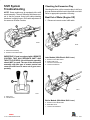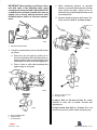
1
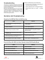
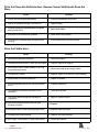
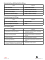
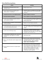
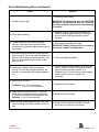
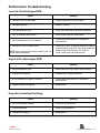
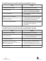
GENERAL INFORMATION
TROUBLESHOOTING
Index
1
C
Table of Contents
Page
Troubleshooting . . . . . . . . . . . . . . . . . . . . . . . . . . 1C-1
Sterndrive Unit Troubleshooting . . . . . . . . . . . . 1C-1
Sterndrive Unit Will Not Slide Into
Bell Housing . . . . . . . . . . . . . . . . . . . . . . . . . 1C-1
Drive Unit Does Not Shift Into Gear; Remote
Control Shift Handle Moves . . . . . . . . . . . . . 1C-1
Drive Unit Does Not Shift Into Gear; Remote
Control Shift Handle Does Not Move . . . . . 1C-2
Drive Unit Shifts Hard . . . . . . . . . . . . . . . . . . 1C-2
Drive Unit In Gear, Will Not Shift Out Of
Gear . . . . . . . . . . . . . . . . . . . . . . . . . . . . . . . . . 1C-3
Drive Unit Jumps Out Of Gear . . . . . . . . . . . 1C-3
Gear Housing Noise . . . . . . . . . . . . . . . . . . . 1C-3
Drive Shaft Housing Noise . . . . . . . . . . . . . . 1C-4
Performance Troubleshooting . . . . . . . . . . . . . . 1C-7
Low Full-Throttle Engine RPM . . . . . . . . . . . 1C-7
High Full-Throttle Engine RPM . . . . . . . . . . 1C-7
Propeller Ventilating/Cavitating . . . . . . . . . . 1C-7
Poor Boat Performance And/Or Poor
Maneuverability-Bow Too Low . . . . . . . . . . 1C-8
Poor Boat Performance And/Or Poor
Maneuverability-Bow Too High . . . . . . . . . 1C-8
Steering System Troubleshooting . . . . . . . . . . 1C-9
Hard Steering - Ride Guide Steering
System . . . . . . . . . . . . . . . . . . . . . . . . . . . . . . 1C-9
Hard Steering Power Steering System . . . . 1C-9
Power Steering System External Fluid
Leaks . . . . . . . . . . . . . . . . . . . . . . . . . . . . . . 1C-10
Power Trim Electrical System . . . . . . . . . . . . . 1C-11
Power Trim Pump Motor Will Not Run In
The Out/Up Or In/Down Direction . . . . . 1C-11
Power Trim Motor Runs In The Out/Up
Direction, Not In The In/Down Direction 1C-12
Power Trim Pump Motor Runs In/Down, But
Not In The Out/Up Direction - . . . . . . . . . 1C-13
Trim Control Out/Up Switch Inoperative . . 1C-14
Trim Control Trailer Switch Inoperative . . 1C-14
Trim System Functions While
Unattended . . . . . . . . . . . . . . . . . . . . . . . . . 1C-14
Auto Trim Electrical System . . . . . . . . . . . . . . 1C-18
Pump Motor Will Not Run Up Or Down In
Either Manual Or Auto Mode . . . . . . . . . . 1C-18
Pump Motor Will Run Up, But Not Down In
Both Manual And Auto Modes . . . . . . . . . 1C-19
Pump Motor Runs Down, But Not Up In Both
The Manual And Auto Modes . . . . . . . . . 1C-20
Pump Motor Will Not Stop Running Down
In Auto Mode . . . . . . . . . . . . . . . . . . . . . . . 1C-21
Pump Motor Will Not Run Up Or Down In
Auto Mode . . . . . . . . . . . . . . . . . . . . . . . . . 1C-21
Pump Motor Will Run Down, But Not Up In
Auto Mode . . . . . . . . . . . . . . . . . . . . . . . . . 1C-22
Pump Motor Will Run Up, But Not Down In
Auto Mode . . . . . . . . . . . . . . . . . . . . . . . . . . 1C-22
Page
Trim System Completely Inoperative In
Manual Mode . . . . . . . . . . . . . . . . . . . . . . . 1C-22
Trim In/Down Switch Inoperative In
Manual Trim Control . . . . . . . . . . . . . . . . . 1C-23
Trim Out/Up Switch And Trailer Switch
Inoperative In Manual Trim Control . . . . 1C-23
Trim Out/Up Switch Inoperative In
Manual Trim Control . . . . . . . . . . . . . . . . . 1C-23
Boat Is On Plane Well Before Drive
Unit Begins To Trim Out . . . . . . . . . . . . . . 1C-24
Boat Is Not On Plane Before Drive
Unit Begins To Plane Out . . . . . . . . . . . . . 1C-24
Auto Trim II System Wiring Diagram . . . . . 1C-25
Power Trim System Troubleshooting Hydraulic System on Oildyne Trim Pump . . 1C-26
Drive Unit Cannot Be Trimmed Out/Up . . 1C-26
Drive Unit Cannot Be Lowered From
Up Position . . . . . . . . . . . . . . . . . . . . . . . . . 1C-27
Drive Unit Will Not Stay In Full Up Position
For Extended Periods . . . . . . . . . . . . . . . . 1C-28
Drive Will Not Stay In The Trimmed Out/Up
Position When Underway . . . . . . . . . . . . . 1C-28
Drive Unit Trails Out/Up On Deceleration Or
When Shifting Into Reverse . . . . . . . . . . 1C-28
Oil Foams Out Of Pump Fill/Vent Screw . 1C-29
The Trim Pump Motor Runs But Does
Not Pump Oil . . . . . . . . . . . . . . . . . . . . . . . 1C-29
Power Trim Hydraulic Schematic . . . . . . . 1C-30
Power Trim System Troubleshooting - Hydraulic
System on Prestolite Trim Pump . . . . . . . . . 1C-31
Drive Unit Cannot Be Trimmed Out/Up . . 1C-31
Drive Unit Cannot Be Lowered From
OUT/UP Position . . . . . . . . . . . . . . . . . . . . 1C-31
Drive Unit Will Not Stay In Full Out/Up
Position For Extended Periods . . . . . . . . 1C-32
Drive Unit Will Not Stay In Trimmed Out/Up
Position When Underway . . . . . . . . . . . . . 1C-32
Drive Unit Trails OUT/UP on Deceleration or
When Shifting into Reverse . . . . . . . . . . 1C-32
Oil Foams Out of Pump “Vent” Screw . . . 1C-32
Prestolite Trim System Diagram . . . . . . . . 1C-33
Corrosion Protection . . . . . . . . . . . . . . . . . . . . . 1C-34
Corrosion Of Underwater Parts, Without Mercathode Or Current Protection . . . . . . . . . . . . 1C-34
Corrosion On Underwater Parts, With Mercathode Or Current Protection . . . . . . . . . . . 1C-34
Corrosion Troubleshooting Procedures . . 1C-37
Shift System Troubleshooting . . . . . . . . . . . . . 1C-38
Checking for Excessive Play . . . . . . . . . . . 1C-38
Isolating Excessive Play . . . . . . . . . . . . . . . 1C-41
Checking Remote Control Shift Cable
Output . . . . . . . . . . . . . . . . . . . . . . . . . . . . . 1C-42
Checking Cutout Switch Timing . . . . . . . . . 1C-44
Checking Operation . . . . . . . . . . . . . . . . . . . 1C-45
Index
1C-0 - TROUBLESHOOTING
90-12934--2 1097
Effective troubleshooting is best enhanced by:
• Personal product knowledge and experience of
the trained mechanic/technician.
Troubleshooting
This section is a guide for performance and product
troubleshooting. Referrals to specific sections of this
manual are made where special tests or repair procedures are to be performed.
• Allowing adequate time for testing and analysis.
• Utilizing these charts as a “guide” - a starting
point.
Because of the relationship between Power Package
components (engine and sterndrive), it will be necessary, in some cases, to simultaneously refer to the
appropriate Engine Service Manual for further
trouble shooting information.
Sterndrive Unit Troubleshooting
Sterndrive Unit Will Not Slide Into Bell Housing
Cause
Remedy
1. U-joint shaft splines not aligned with engine
coupler splines.
1. Rotate propeller shaft COUNTERCLOCKWISE
to align splines.
2. Engine not aligned.
2. Check engine alignment.
3. Gimbal bearing not properly installed.
3. Check engine alignment to determine if gimbal
bearing is cocked, or improperly installed in
gimbal housing.
4. Damaged u-joint shaft splines and/or engine
coupler splines.
4. Inspect and replace if necessary.
5. Lower shift shaft not in forward gear position.
Bell Housing shift shaft not lined up.
5. Properly align shift shafts.
6. Bell housing shift shaft coupler not aligned.
6. Place coupler in forward gear position.
Drive Unit Does Not Shift Into Gear; Remote Control Shift Handle Moves
Cause
Remedy
1. Shift cables improperly adjusted.
1. Adjust shift cables.
2. Shift cables not connected.
2. Install and adjust shift cables.
3. Inner core wire broken or loose.
3. Reconnect or replace inner core wire.
4. Gear housing crank improperly installed.
4. Install shift crank properly.
Index
90-12934--2 1097
TROUBLESHOOTING - 1C-1
Drive Unit Does Not Shift Into Gear; Remote Control Shift Handle Does Not
Move
Cause
Remedy
1. Control box not properly assembled.
1. Properly reassemble control box.
2. Broken or damaged linkage in control box.
2. Repair linkage.
3. Controls improperly adjusted-cable end guide
hitting brass barrel.
3. Adjust shift cables.
4. Shift shaft or shift shaft lever jammed.
4. Install shift crank properly.
5. Shift cable not installed deep enough into bell
housing.
5. Install cable further into bell housing.
Drive Unit Shifts Hard
Cause
1. Shift cables improperly adjusted.
Remedy
1. Adjust shift cables.
2. Damaged remote control or drive unit shift cable. 2. Replace cable(s) and adjust.
3. Shift cable too short (sharp bends) or too long
(loops and long bends).
3. Select and install proper length cable.
4. Corroded shift cables.
4. Replace, adjust, and check for water leakage.
5. Internal wear in remote control box.
5. Repair as needed.
6. Shift cable attaching nuts too tight (end cannot
pivot).
6. Properly install nuts.
7. Shift cable pivot ends are corroded, or not
lubricated.
7. Clean and lubricate.
8. Shift cutout switch improperly adjusted or
inoperative.
8. Adjust or replace switch.
10 Shift shaft bushing in bell housing or gear
housing corroded.
10. Replace.
11. Shift crank and/or clutch actuating spool worn.
11. Replace crank and spool.
12. Damaged shift shaft bushing.
12. Replace shift shaft bushing.
13. Bent upper, intermediate, or lower shift shaft(s).
13. Inspect and replace.
Index
1C-2 - TROUBLESHOOTING
90-12934--2 1097
Drive Unit In Gear, Will Not Shift Out Of Gear
Cause
Remedy
1. Shift cable broken.
1. Replace cable and adjust.
2. Cable end not connected in drive unit.
2. Remove and reinstall drive unit.
3. Remote control damaged.
3. Repair or replace remote control.
4. Internal shift mechanism damage.
4. Repair or replace as necessary.
Drive Unit Jumps Out Of Gear
Cause
Remedy
1. Shift cables improperly adjusted.
1. Adjust shift cables.
2. Worn or damaged clutch and gears.
2. Repair.
Gear Housing Noise
Cause
Remedy
1. Metal particles in drive unit lubricant.
1. Disassemble, clean and inspect, and replace
necessary components.
2. Propeller incorrectly installed.
2. Inspect mounting hardware. Install propeller
correctly.
3. Propeller shaft bent.
3. Inspect and replace if necessary.
4. Incorrect gear shimming.
4. Check gear housing backlash and pinion gear
height.
5. Worn or damaged gears and/or bearings caused
5. Disassemble, inspect, replace.
by impact, overheating, or improper shimming.
Index
90-12934--2 1097
TROUBLESHOOTING - 1C-3
Drive Shaft Housing Noise
Cause
Remedy
1. Steering lever contacting transom cutout
opening in turns.
1. Modify transom cutout.
2. Engine flywheel housing contacting inner
transom plate or exhaust pipe.
2. Determine cause for interference (loose engine
mounts, transom too thin, etc.) and correct as
necessary.
3. Propeller with untrue or out-of-balance blades.
3. Repair or replace, as required.
4. Abnormal sterndrive operation.
4. Instruct operator on proper operating technique.
5. U-joint cross and bearing assembly retaining
rings improperly installed.
5. Make sure that proper thickness retaining rings
are used and that rings are fully seated in u-joint
bearing cap grooves.
6. Excessive side-to-side play in u-joint cross and
bearing assemblies.
6. Replace cross and bearing assembly.
7. U-joint bearing caps contacting center socket or
drive shaft housing bearing retainer.
7.
Make sure proper cross and bearing assemblies
are used. If interference is noted, replace center
socket.
8. U-joint cross and bearings rough.
8. Disassemble cross and bearing assemblies and
inspect. DO NOT RELY ON FEEL. Replace
assemblies if they show signs of scoring, galling,
roughness, lack of lubricant, etc.
9. O-rings missing or flattened out on u-joint shaft
causing shaft to rattle against ID of gimbal
bearing.
9. Install new o-rings.
10. Worn u-joint shaft splines and/or engine coupler
splines.
10. Remove u-joint coupling end yoke and insert
into gimbal bearing and engine coupling. Rotate
shaft back-and-forth. If play is excessive,
replace u-joint coupling end yoke and/or
engine coupler, as necessary.
11. Engine alignment incorrect or engine coupler
crooked.
11. Adjust alignment, making sure that alignment
tool moves in-and-out of coupler freely. After
proper alignment has been obtained, check for a
cocked coupler by rotating engine coupler 1/2
turn and rechecking alignment. If proper
alignment is no longer observed, coupler is
crooked and must be replaced.
Index
1C-4 - TROUBLESHOOTING
90-12934--2 1097
Drive Shaft Housing Noise (continued)
Cause
Remedy
12. Replace gimbal bearing.
12. Gimbal bearing rough.
13. Loose gimbal bearing.
14. Gimbal bearing not fully seated in gimbal
housing. Yoke moves back and forth when
turning and may hammer against bearing if not
fully seated.
IMPORTANT: Gimbal bearing and carrier MUST BE
replaced as an assembly as they are a matched
set. Failure to do this may result in a loose bearing
fit in carrier.
13. Reinstall bearing using a new tolerance ring if
carrier is loose in gimbal housing. If bearing is
loose in carrier, bearing assembly must be
replaced.
14. Drive bearing assembly into place.
IMPORTANT: Gimbal bearing must be pressed in
past lead-in chamfer in bearing bore.
15. Excessive clearance between gimbal ring and
gimbal housing. This could cause misalignment
between bell housing and gimbal housing, and
also may allow gimbal ring to vibrate up-anddown, in turns.
15. Check and adjust clearance.
16. Improperly installed or failed rear engine
mounts. This will affect engine alignment, but
usually is not detectable with engine alignment
tool.
16. Check for uneven mount height, or loose or soft
mounts. Make sure there is clearance between
flywheel housing and fiber washer. If no
clearance exists, mounts have probably sagged.
Install mounts correctly or replace, as
necessary.
17. Boat transom too thin.
Thickness: 2 in. (51 mm) minimum
2-1/4 in. (57 mm) maximum
17. Add thickness to transom.
18. Boat transom thickness uneven. This could
affect engine to transom assembly alignment.
It is usually not detectable with alignment tool.
Variation: 1/8 in (3 mm) maximum
18. Repair boat as necessary.
19. Bell housing contacting gimbal ring. This would
cause knocking in the fully trimmed IN position
only.
19. Check for soft or split trim cylinder bushings,
and loose or worn hinge pin bushings.
Index
90-12934--2 1097
TROUBLESHOOTING - 1C-5
Drive Shaft Housing Noise (continued)
Cause
Remedy
20. Stringer height uneven or transom assembly
installed crooked on boat transom. This will
affect engine alignment, but is usually not
detectable with alignment tool.
20. Measure the distance between the engine
flywheel housing and the inner transom plate on
both sides. If distances are uneven, the
problem may be due to uneven stringer height
or a cocked transom assembly. Adjust the
stringer height or relocate the transom cutout
as required.
21. Weak boat transom or boat bottom that flexes
under power and causes engine misalignment this condition will usually cause engine coupler
failure.
21. This condition can sometimes be detected by
having someone apply force to the top of the
drive unit while watching the inner transom
plate. If movement can be observed, the
transom is weak and must be repaired.
22. Rear engine mount attaching hardware
improperly installed or missing.
22. Reinstall hardware correctly.
23. Engine mounting holes drilled off-center in inner
transom plate engine supports or engine
flywheel housing
23. Make sure the holes are equally spaced fore
and aft and are equal distance from the
centerline.
24. Misalignment between bell housing, gimbal
housing and engine coupler.
24. Contact your regional service center and
arrange to have a technical service
representative check the unit using a special
gauge.
Index
1C-6 - TROUBLESHOOTING
90-12934--2 1097
Performance Troubleshooting
Low Full-Throttle Engine RPM
Cause
Remedy
1. Improper drive unit trim angle.
1. Properly adjust drive unit trim angle.
2. Damaged propeller.
2. Repair or replace.
3. Improper propeller pitch.
3. Water test boat using a lower pitch propeller.
4. Dirty or damaged boat bottom.
4. Clean and/or resurface boat bottom.
5. Drive installation too low on transom.
5. Contact boat manufacturer for installation
specifications.
6. Permanent “hook” in boat bottom.
6.
NOTE: Some boats are built with a slight “hook” for
correct boat performance.
Check for a “hook” in the boat bottom by placing
a straight edge, at least 6ft. (2m) long, under the
bottom edge of the transom. If a “hook” is
found, contact the boat manufacturer.
High Full-Throttle Engine RPM
Cause
Remedy
1. Improper propeller pitch.
1. Water test boat using a higher pitch propeller.
2. Propeller hub slipping.
2. Replace hub or replace propeller.
3. Drive installation too high on transom.
3. Contact boat manufacturer for installation
specifications.
4. Engine coupler hub slipping.
4. Replace hub.
Propeller Ventilating/Cavitating
Cause
Remedy
1. Drive unit trimmed too high.
1. Trim drive unit IN/DOWN.
2. Incorrect propeller.
2. Install correct propeller.
3. Propeller hub slipping.
3. Replace hub.
Index
90-12934--2 1097
TROUBLESHOOTING - 1C-7
Poor Boat Performance And/Or Poor Maneuverability-Bow Too Low
Cause
Remedy
1. Improper drive unit trim angle.
1. Properly adjust drive unit trim angle.
2. Boat is bow heavy.
2. Redistribute boat load to stern. If bow over
weigh is caused by permanently installed fuel
tank(s), etc., contact the boat manufacturer.
3. Boat is underpowered.
3. Check horsepower to weight ratio. Contact the
boat manufacturer.
4. Permanent “hook” in boat bottom.
4. Check for a “hook” in the boat bottom by placing
a straight edge, at least 6ft. (2m) long, under
NOTE: Some boats are built with a slight “hook” for
the bottom edge of the transom. If a “hook” is
correct boat performance.
found, contact the boat manufacturer.
5. Power hook or weak boat bottom.
5. Water test boat. Boat will perform normally until
hook develops at high speed: then loss of RPM
and speed will occur. Contact boat
manufacturer.
Poor Boat Performance And/Or Poor Maneuverability-Bow Too High
Cause
Remedy
1. Improper drive unit trim angle.
1. Properly adjust drive unit trim angle.
2. Boat is stern heavy.
2. Redistribute boat load to bow. If stern overweight
is caused by permanently installed fuel tank(s),
etc., contact the boat manufacturer.
3. Propeller pitch too high.
3. Water test the boat using a lower pitch propeller.
4. Permanent “rocker” in boat bottom.
NOTE: Some boats are built with a slight “rocker”
for correct boat performance.
4. Check for a “rocker” in the boat bottom by
placing a straight edge, at least 6 ft. (2m) long,
under the bottom edge of the transom. If a
“rocker” is found, contact the boat manufacturer.
5. Dirty boat bottom.
5. Clean boat bottom.
Index
1C-8 - TROUBLESHOOTING
90-12934--2 1097
Steering System
Troubleshooting
If Power Package is equipped with Power Steering,
first determine if problem is caused by the Power
Steering System or Ride Guide portion of the steering system.
2. Remove clevis pin which secures piston rod end
clevis to stern drive steering lever.
3. Turn steering wheel thru entire steering range. If
steering difficulty is encountered problem is located in Ride Guide steering system.
If steering wheel turns with ease, problem is located
in Power Steering system.
Proceed as follows:
1. Remove clevis pin which attaches steering cable
to Power Steering unit piston rod end clevis.
Hard Steering - Ride Guide Steering System
Cause
Remedy
1. Damaged steering cable.
1. Replace cable.
2. Steering cable too short (sharp bends) or too
long (loops and long bends).
2. Select and install proper length cable.
3. Steering cable corroded or not lubricated.
3. Lubricate or replace the cable.
4. Ride Guide rack or rotary head not lubricated.
4. Disassemble and lubricate.
Hard Steering (Engine Running) Power Steering System
Cause
Remedy
1. Low power steering pump fluid level.
1. Check fluid level.
2. Loose power steering pump drive belt.
2. Adjust belt tension.
3. Air in system.
3. Locate source of air in lines or fittings. Correct
and air bleed system.
4. Fluid leak.
4. Locate and correct source of leak.
5. If the above 4 steps do not solve the problem,
test the power steering system.
5. Test power steering system.
Index
90-12934--2 1097
TROUBLESHOOTING - 1C-9
Power Steering System External Fluid Leaks
Cause
Remedy
1. Pump reservoir leaking at fill cap (reservoir too
full).
1. Remove fluid to bring to proper level.
2. Pump reservoir leaking at fill cap (air or water in
fluid).
2. Locate source of air or water and correct. Air
may enter because of low reservoir fluid level or
internal pump leak. Test pump.
3. Loose hose connections.
3. Tighten hose connections.
4. Damaged hose.
4. Replace hose.
5. Bad cylinder piston rod seal.
5. Replace seal.
6. Damaged or worn control valve seals.
6. Replace seals.
7. Bad power steering pump seals and o-rings.
7. Repair pump.
8. Cracked or porous metal parts.
8. Replace part(s).
Index
1C-10 - TROUBLESHOOTING
90-12934--2 1097
Power Trim Electrical System
Power Trim Pump Motor Will Not Run In The Out/Up Or In/Down Direction
(Solenoids Do Not Click)
IMPORTANT: Refer to wiring diagram at end of this section for assistance in electrical system troubleshooting.
Cause
1. Thermal circuit breaker in pump motor broken.
Remedy
1. Replace commutator end plate assembly.
2. Determine cause for blown fuse and correct
before replacing fuse
2. 20 amp fuse blown.
NOTE: If fuse blows while trimming “Out/Up” or raising
drive unit, problem may be due to grounded trim limit
switch leads. To check for grounded condition, disconnect trim limit switch leads at bullet connector “14,”
“15,” “16,” and “17” (in wiring diagram). If drive unit can
now be raised (using “Trailer” switch), trim limit switch
or leads are grounded.
3. Power trim pump battery cables or wiring
harness connections corroded or lose.
3. Clean and or tighten connections “1”, “2,” “4,”
“10,” “11,” “12,” and “18,” as necessary.
4. Trim control wiring harness connector loose or
corroded.
4. Clean and secure connection “13” as necessary.
5. 110 amp fuse blown.
NOTE: Does not apply to an intermittent problem.
6. Open circuit in trim control wiring harness.
5.
Check for voltage at terminal “4.” If no voltage is
indicated, determine cause for blown fuse and
correct, then replace fuse. Trimming OUT/UP
and IN/DOWN simultaneously will blow fuse)
6. Check for battery voltage at terminal “8” while
trimming OUT/UP and at terminal “6” while
trimming IN/DOWN. If no voltage is indicated,
check trim control for a loose or corroded
connection or a damaged power supply lead in
harness
Index
90-12934--2 1097
TROUBLESHOOTING - 1C-11
Power Trim Pump Motor Will Not Run In The Out/Up Or In/Down Direction (Both
Solenoids Click)
Cause
Remedy
1. Faulty solenoids or loose or corroded
connections.
1. Check for battery voltage at terminal “5” (in
wiring diagram) while trimming IN/DOWN and
at terminal “3” while trimming OUT/UP. If no
voltage is indicated check connections “2,” “3,”
“4” and “5” and/or replace solenoids.
2. Pump motor brushes stuck, corroded or worn
out.
2. Clean or replace, as required.
3. Armature commutator dirty.
3. Clean or replace armature, as required.
4.
4. Test for shortened, open or grounded condition
and replace if bad.
Armature faulty.
5. Field and frame faulty.
5.
Check for open or grounded condition. Replace
field and frame assembly, if bad.
6. Pump gears froze.
6. Replace pump valve body and gear assembly.
7. Power trim pump harness or trim control
harness shortened
7. Disconnect blue-white lead from solenoid
terminal “8.” If pump motor will now run in the
IN/DOWN direction, a short in harness exists.
Repair or replace harness, as necessary.
Power Trim Motor Runs In The Out/Up Direction, But Not In The In/Down
Direction (In/Down Solenoid Does Not Click)
Cause
Remedy
1. Loose or dirty solenoid connections.
1. Check connections “6,” “7,” “8,” and “9” (in
wiring diagram) and clean and/or tighten, as
required.
2. Open IN/DOWN circuit in trim control or pump
wiring harness.
2. Check for battery voltage at terminal “6” while
trimming IN/DOWN. If no voltage is indicated,
check for a loose or corroded IN/DOWN circuit
connection, damaged IN/DOWN circuit lead or
a faulty IN/DOWN trim switch. Repair or
replace, as required
3. Solenoid faulty.
3. Replace solenoid.
Index
1C-12 - TROUBLESHOOTING
90-12934--2 1097
Power Trim Motor Runs In The In/Down Direction, But Not In The Out/Up
Direction - Both Trim And Trailer Switches Inoperative-(Out/Up Solenoid Does
Not Click)
Cause
Remedy
1. Loose or dirty solenoid connections.
1. Check connections “8” and “9.” Clean and/or
tighten as necessary.
2. Open OUT/UP circuit trim control or pump
wiring harness.
2. Check for battery voltage at terminal “8” while
trimming OUT/UP. If no voltage is indicated,
check for a loose or corroded OUT/UP circuit
connection, blown fuse (if trim control is so
equipped), damaged OUT/UP circuit lead, or a
faulty OUT/UP trim switch. Repair or replace
as necessary.
3. Solenoid faulty.
3. Replace solenoid.
Power Trim Pump Motor Runs In The Out/Up But Not In The In/Down Direction In/Down Solenoid Clicks
Cause
Remedy
1. Loose or dirty solenoid connections.
1. Check connections “4” and “5” (in wiring
diagram) and clean and/or tighten, as required.
2. Faulty solenoid
2. Check for battery voltage at terminal “5” while
trimming IN/DOWN. If no voltage is indicated,
replace solenoid.
3. Faulty IN/DOWN field winding
3. Replace field and frame assembly.
Power Trim Pump Motor Runs In The In/Down Direction, But Not In The Out/Up
Direction - Both Trim And Trailer Switches Inoperative - (Out/Up Solenoid
Clicks)
Cause
Remedy
1. Loose or dirty solenoid connection.
1. Check connections “2” and “3” (in wiring
diagram). Clean and/or tighten, as necessary.
2. Open OUT/UP circuit in trim control or pump
wiring harness.
2. Check for battery voltage at terminal “3” while
trimming OUT/UP. If no voltage is indicated,
replace solenoid.
3. Solenoid faulty
3. Replace solenoid.
Index
90-12934--2 1097
TROUBLESHOOTING - 1C-13
Trim Control Out/Up Switch Inoperative (Trailer Switch Operates)
Cause
1.
Trim limit switch lead bullet connectors loose or
corroded.
Remedy
1.
Clean and/or tighten connections “14,” “15,” “16”
and “17” (in wiring diagram), as necessary.
2. Trim limit switch or leads faulty.
2. Disconnect trim limit switch leads from trim
harness. Connect a continuity meter between
leads “16” and “17.” Continuity should be
indicated with drive unit in full IN/DOWN
position. If not, check for damaged leads or poor
connections. If this is not the cause, replace limit
switch.
3. Open in trim control OUT/UP circuit
3. Check for a loose or corroded OUT/UP circuit
connection, damaged OUT/UP circuit lead or
faulty OUT/UP trim switch. Repair or replace,
as necessary.
Trim Control Trailer Switch Inoperative (Trim Out/Up Switch Functions)
Cause
Open trim control trailer circuit.
Remedy
Check for a faulty trailer switch, loose or corroded
connections, or damaged trailer circuit lead.
Trim System Functions While Unattended
Cause
Remedy
1. Faulty trim or trailer switch.
1. Replace switch.
2. Shorted trim pump harness or trim control
harness.
2. Repair or replace as required.
Index
1C-14 - TROUBLESHOOTING
90-12934--2 1097
Power Trim
BLK
BLU
BRN
GRY
GRN
ORN
PNK
PUR
RED
TAN
WHT
YEL
LIT
DRK
=
=
=
=
=
=
=
=
=
=
=
=
=
=
BLACK
BLUE
BROWN
GRAY
GREEN
ORANGE
PINK
PURPLE
RED
TAN
WHITE
YELLOW
LIGHT
DARK
22252
Wiring Diagram (With 3-Button Trim Control)
Index
90-12934--2 1097
TROUBLESHOOTING - 1C-15
26351
Power Trim Electrical System Wiring Diagram (with 3-Button Trim Control)
Index
1C-16 - TROUBLESHOOTING
90-12934--2 1097
26347
Index
90-12934--2 1097
TROUBLESHOOTING - 1C-17
Auto Trim Electrical System
NOTE: Refer to wiring diagram, following, for assistance in electrical system troubleshooting.
Pump Motor Will Not Run Up Or Down In Either Manual Or Auto Mode
(Solenoids Click)
Cause
1.
Pump positive battery cable connection loose or
corroded.
Remedy
1. Check cable “14.”
2. 110 amp fuse blown or loose, or corroded
solenoid connection.
2. Check for voltage at terminal “5.”
3. Pump motor brushes stuck, corroded or worn
out.
3. Clean or replace.
4. Armature commutator dirty.
4. Clean or replace.
5. Armature faulty.
5. Test and replace if bad.
6. Field and frame faulty.
6. Test and replace if bad.
7. Pump gears frozen.
7. Replace pump adaptor.
8. Trim harness shorted between UP and DOWN
circuit.
8. Disconnect blue-white lead “2” from solenoid
terminal. If pump motor will now run in the
DOWN direction, a short in the harness is
indicated.
Index
1C-18 - TROUBLESHOOTING
90-12934--2 1097
Pump Motor Will Not Run Up Or Down In Either Manual Or Auto Mode
(Solenoids Do Not Click)
Cause
Remedy
1. Pump negative battery cable loose, corroded or
damaged
1. Check cable “13” for a loose or corroded
connection, or damage.
2. Mode switch wiring harness connector is loose
at pump.
2. Secure connection “47.”
3. Faulty thermal circuit breaker in pump motor.
3. Connect a jumper wire between terminals “1”
and “7.” If pump now operates, circuit breaker is
faulty and field and frame assembly must be
replaced.
4. Open circuit in mode switch wiring harness.
4. With ignition switch in “Run” position and mode
switch in “Manual” mode, check for voltage at
terminal “8” while trimming UP and terminal
12” while trimming DOWN. If no voltage is
indicated, refer to items “5” and “6” immediately
following.
5. No power to mode switch.
5. Check for voltage at terminal “25” (with ignition
switch in “Run” position). If no voltage is
indicated, check power lead for a poor
connection.
6. Faulty mode switch.
6. Check for voltage at terminal “24” (with mode
switch in “Auto” mode) and terminal “26” (with
switch in the “Manual”mode). Replace switch if
no voltage is indicated.
Pump Motor Will Run Up, But Not Down In Both Manual And Auto Modes
(Down Solenoid Does Not Click)
Cause
1. Loose or Dirty solenoid connections.
Remedy
1. Check connections “4,” “7,” and “12.”
2. Check for voltage at terminal “12” while trimming
2. Faulty mode switch or open in DOWN circuit.
3. Faulty DOWN solenoid.
DOWN (in “Manual” mode). If no voltage is
indicated, repeat test at terminal “22” and “23.”
If voltage exists at terminal “23,” but not at “22”
switch is faulty. If voltage is present at terminal
“22,” check leads “3” and “48” and connector
“47” for an open condition.
3. Replace.
Index
90-12934--2 1097
TROUBLESHOOTING - 1C-19
Pump Motor Will Run Up, But Not Down In Both Manual And Auto Modes
(Down Solenoid Clicks)
Cause
Remedy
1. Loose or dirty solenoid connections.
1. Check connections “10” and “11.”
2. Faulty solenoid.
2. Check for voltage at terminal “11” while trimming
DOWN (in “Manual” mode). If no voltage is
indicated, replace solenoid.
3. Faulty DOWN field winding.
3. Replace field and frame.
Pump Motor Runs Down, But Not Up In Both The Manual And Auto Modes
(Up Solenoid Clicks)
Cause
Remedy
1. Loose or dirty solenoid connections.
1. Check connections “5” and “6.”
2. Faulty solenoid.
2. Check for voltage at terminal “6” while trimming
UP. If no voltage is indicated, replace solenoid.
3. Faulty UP field winding.
3. Replace field and frame.
Pump Motor Runs Down, But Not Up In Both the Manual and Auto Mode (Up Solenoid Does Not Click)
1. Faulty solenoid
1. Replace solenoid
Index
1C-20 - TROUBLESHOOTING
90-12934--2 1097
Pump Motor Will Not Stop Running Down In Auto Mode (Trim Out/Up Switch
And Trailer Switch Inoperative In Manual Mode)
NOTE: An internal timer in the control module stops the pump motor 50 seconds after this condition occurs.
Cause
Remedy
1. Loose or dirty solenoid connection.
1. Check connections “7” and “8.”
2. Faulty solenoid.
2. Check for voltage at terminal “8” while trimming
UP (in Manual mode). If voltage exists, an
open condition in solenoid is indicated and
solenoid must be replaced. If no voltage is
indicated, refer to steps 3 through 6 following.
3. Loose or corroded trim limit switch lead
connections.
3. Check connections “32” and “36.”
4. Faulty trim limit switch.
4. Disconnect trim limit switch leads “32” and “36”
and connect a continuity meter between leads.
Continuity should exist with drive unit in DOWN
position. If not, readjust or replace switch as
necessary.
5. Open circuit in wiring harness.
6. Faulty control module.
5.
Check leads “30,” “35,” “46,” and “2” for loose or
corroded connections or physical damage.
6. Replace.
Pump Motor Will Not Run Up Or Down In Auto Mode (Manual Mode Functions
Properly)
Cause
Remedy
1. Open in control module battery cables or wiring
harness.
1. Check cables “16” and “18,” and lead “20.”
2. Faulty mode switch.
2. Check for voltage at terminal “24” and “25” with
switch in Auto mode. If voltage exists at terminal
“25,” but not “24,” switch is faulty.
3. Faulty control module.
3. Replace.
Index
90-12934--2 1097
TROUBLESHOOTING - 1C-21
Pump Motor Will Run Down, But Not Up In Auto Mode (Manual Mode Functions
Properly)
1. Open circuit in control module sense lead.
1. Check lead “17” (in Figure 12) for loose or
corroded connections or damage.
2. Faulty control module.
2. Replace.
Pump Motor Will Run Up, But Not Down In Auto Mode (Manual Mode Functions
Properly)
Cause
Remedy
1.
1. Faulty mode switch.
Check for voltage at terminal “21” and “22” while
turning ignition switch to “Run” position (in “auto”
mode). If voltage exists at “21”, but not at “22”,
switch is faulty.
2. Open circuit in wiring.
2. Check lead “19” for a loose or corroded
connection or damage.
3. Faulty control module.
3. Replace.
Trim System Completely Inoperative In Manual Mode (Auto Mode Functions
Properly)
Cause
1. Faulty mode switch.
2. Open circuit wiring harness.
Remedy
1. Check for voltage at terminal “26” with mode
switch in “Manual” mode. If no voltage is
indicated, replace switch.
2.
Check leads “27” and “33” for loose or corroded
connections or damage.
Index
1C-22 - TROUBLESHOOTING
90-12934--2 1097
Trim In/Down Switch Inoperative In Manual Trim Control - Trim Out/Up Switch
and Trailer Switch Function (Auto Mode Functions Properly)
Cause
Remedy
1.
1. Faulty IN/DOWN switch in manual trim control.
2.
2. Open circuit in wiring harness.
3. Faulty mode switch.
3.
Check for voltage at terminal “38” while trimming
IN/DOWN (in “Manual” mode). If no voltage is
indicated, switch is faulty.
Check for voltage at terminal “23” while trimming
IN/DOWN. If no voltage is present, check leads
“28” and “34” for a loose or corroded connection
or damage.
Check for voltage at terminal “22” while trimming
IN/DOWN. If no voltage exists, switch is faulty.
Trim Out/Up Switch And Trailer Switch Inoperative In Manual Trim Control Trim In/Down Switch Operates (Auto Mode Functions Properly)
Cause
1.
Trim control 20 amp fuse (if so equipped) - “43”
blown.
Remedy
1. Determine cause for blown fuse and correct
before replacing fuse.
2. Open in power supply lead to trim and trailer
switch.
2. Check voltage at terminal “44.” If no voltage is
indicated, check lead “45” for a poor connection
or damage.
3. Faulty trim OUT/UP switch (applies only to trim
controls where it is necessary to actuate trim
UP switch in order for trailer switch to function).
3. Check for voltage at terminal “40” while
actuating trim OUT/UP switch. Replace
switch if no voltage is indicated.
Trim Out/Up Switch Inoperative In Manual Trim Control - Trailer Switch
Operates Properly (Auto Mode Functions Correctly)
Cause
Remedy
1. Faulty trim OUT/UP switch (applies only to
1. While actuating switch, check for voltage at
trim controls where it is not necessary to actuate
output terminal. Replace switch if voltage is
trim UP switch in order for trailer switch to
not indicated.
function - not shown).
2. Open circuit in wiring harness
2.
Check leads “31” and “37” for loose or corroded
connections or damage.
3. Faulty control module.
3. Replace.
Index
90-12934--2 1097
TROUBLESHOOTING - 1C-23
Trailer Switch Inoperative In Manual Trim Control - Trim Out/Up Switch
Functions
Cause
Remedy
1.
1. Faulty trailer switch.
Check for voltage at terminal “41” and “42” while
actuating trailer switch. If voltage exists at
terminal “42,” but not at terminal “41,” a faulty
switch is indicated. If no voltage exists at
terminal “42,” check power supply lead for an
open.
2. Check lead “39” for a loose or corroded
connection or damage.
2. Open in wiring.
Boat Is On Plane Well Before Drive Unit Begins To Trim Out
Cause
Remedy
1. Control module adjustment incorrect.
1. Refer to SECTION 5 for adjustment procedure.
2. Faulty control module.
2. Replace control module.
Boat Is Not On Plane Before Drive Unit Begins To Plane Out
Cause
Remedy
1. Control module adjustment incorrect.
1. Refer to SECTION 5 for adjustment.
2. Faulty control module.
2. Replace control module.
Index
1C-24 - TROUBLESHOOTING
90-12934--2 1097
Auto Trim II System Wiring Diagram
BLK
BLU
BRN
GRY
GRN
ORN
PNK
PUR
RED
TAN
WHT
YEL
LIT
DRK
=
=
=
=
=
=
=
=
=
=
=
=
=
=
BLACK
BLUE
BROWN
GRAY
GREEN
ORANGE
PINK
PURPLE
RED
TAN
WHITE
YELLOW
LIGHT
DARK
18
1
14
8
7
6
2
5
9
13
10
12
47
4
11
46
15
21
43
41
42
22
25
44
39
40
16
23
26
29
45
30
34
38
36
19
24
37
33
31
17
32
35
22178
Index
90-12934--2 1097
TROUBLESHOOTING - 1C-25
Power Trim System Troubleshooting - Hydraulic System on
Oildyne Trim Pump
NOTE: The callouts (eg. “5”) in the Hydraulic System troubleshooting section refer to the hydraulic schematic
on page 1C - 31.
Drive Unit Cannot Be Trimmed Out/Up, Trims Slowly Or Trims With Jerky
Movements
Cause
Remedy
1. Power Trim pump oil level low.
1. Check for cause of low oil level and correct. Add
oil and bleed trim system.
2. Air in trim system.
2. Check for cause of entry and correct. Add oil to
pump and bleed air from system.
3. O-rings damaged on Manual Release Valve
(if equipped) or valve not completely closed.
3. Replace valve and/or close completely.
4. Test (as explained in “Testing Power Trim
Pump”, (Sec 5A). If shuttle “1” is stuck, replace
pump adaptor (Sec 5A). If pressure is low,
4. Insufficient pump pressure or pump shuttle valve
replace adaptor or attempt to repair by
stuck.
replacing the following components:
OUT/UP pressure relief valve
Thermal relief valve
5. Hoses reversed on one cylinder only.
5. Connect hoses “7” and “8” correctly.
6. Trim cylinder(s) binding.
6. Check for cause of binding (bent piston rod,
scored cylinder, etc.). Repair or replace as
necessary.
7. Gimbal housing-to-trim pump hydraulic hose
pinched.
7. Replace hose “7.”
8. Up pressure relief valve has dirt particles under
check ball.
8. Replace with a new valve kit.
9. Relief balls stuck in the up side of the pump
assembly.
9. Replace the pump assembly in the adapter.
10. Dirt or foreign material under the up pressure
relief valve.
10. Replace the up pressure relief valve assembly.
11. Check the condition of the oil, it may be
contaminated and thick like honey.
11. Remove the reservoir and clean out the
contaminated oil.
12. A possible tight adaptor pump gear, or water or
oil in the motor.
12. Replace the pump assembly in the adaptor, or
replace the electric motor assembly.
Index
1C-26 - TROUBLESHOOTING
90-12934--2 1097
Drive Unit Cannot Be Lowered From Up Position Or Lowers With Jerky
Movements
Cause
Remedy
1. Air in trim system.
1. Check for cause of entry. Fill and bleed trim
system.
2. Low oil level.
2. Add oil.
3. Damaged O-rings on manual release valve
(if equipped).
3. Replace valve.
4. Insufficient IN/DOWN pressure or shuttle “1”
valve stuck.
4. Test (as explained in “Testing Power Trim
Pump”, Sec 5A). If shuttle “1” is stuck, replace
pump adaptor. (Sec 5A) If pressure is low,
replace adaptor or attempt to repair by replacing
the following item:
IN/DOWN pressure relief valve “6.”
5. Trim cylinder(s) block leaking internally.
5. Test. Rebuild or replace cylinder as necessary.
6. Trim cylinder(s) “5” binding.
6. Check for cause of binding. Repair or replace
as necessary.
7. Gimbal housing-to-trim pump hydraulic hose “8”
or “7” pinched.
7. Replace hose “8” or “7.”
8. Hoses “10” and “11” reversed on one trim
cylinder only.
8. Reconnect hoses “10” and “11” correctly.
9. Drive unit binding in gimbal ring.
9. Check for cause of binding and replace.
10. Down Pressure relief valve “6” has dirt particles
under check ball.
10. Replace with a new valve kit.
11. Foreign material under down pressure relief
valve.
11. Replace the down pressure relief valve
assembly
12. Dirt or foreign material under the down
pressure relief valve
12. Replace the down pressure relief valve
assembly
13. Check the condition of the oil, it may be
contaminated and thick like honey
13. Remove the reservoir and clean out the
contaminated oil
14. A possible tight adaptor pump gear, or water or
oil in the motor
14. Replace the pump assembly in the adaptor, or
replace the electric motor assembly
Index
90-12934--2 1097
TROUBLESHOOTING - 1C-27
Drive Unit Will Not Stay In Full Up Position For Extended Periods
Cause
Remedy
1. External leakage.
1. Check for cause and correct. Add oil to pump
and bleed trim system.
2. Damaged o-ring on manual release valve (if so
equipped) or valve not closed completely.
2. Replace valve and/or close completely.
3. Pump OUT/UP circuit leaking internally.
3. Test. Replace adaptor “2” or attempt to repair
by replacing the following:
Thermal relief valve “4”
Pilot check valve or seals “9”
4. Trim cylinder(s) leaking internally and pump
DOWN circuit leaking internally (both must be
faulty to cause this problem).
4. Rebuild cylinders “5.” Repair or replace adaptor
“2” as required.
5. Either Foreign Material under the poppet valve
seat or a bad rubber seat on the face of the
poppet valve.
5. Install an Overhaul Kit.
Drive Will Not Stay In The Trimmed Out/Up Position When Underway
NOTE: Use the following in conjunction with items mentioned under “Drive Unit Will Not Stay In Full ‘Up’ Position
For Extended Periods”
Cause
Remedy
1. Air in trim system.
1. Check for cause of entry. Fill and bleed system.
2. Leaky shuttle poppet valve “1.”
2. Install repair kit for shuttle valve “1.”
Drive Unit Trails Out/Up On Deceleration Or When Shifting Into Reverse (Unit
Thumps When Shifting)
Cause
Remedy
1. Trim cylinders(s) leaking internally.
1. Test. Rebuild or replace
cylinders as necessary.
2. Trim pump IN/DOWN circuit leaking internally.
2. Test. Replace adaptor or attempt to
repair by replacing the following:
Pilot check valves or seals “9”
Install trim pump rebuild kit
Index
1C-28 - TROUBLESHOOTING
90-12934--2 1097
Oil Foams Out Of Pump Fill/Vent Screw
Cause
Remedy
1. Contaminated oil.
1. Flush system with clean oil refill pump and bleed
trim system.
2. Oil level low.
2. Check for cause of low oil level and correct.
Add oil to pump and bleed system.
The Trim Pump Motor Runs But Does Not Pump Oil
Cause
1. Broken coupler between the pump and the
motor.
Remedy
1. Replace the coupler.
Index
90-12934--2 1097
TROUBLESHOOTING - 1C-29
Power Trim Hydraulic Schematic
1 - Shuttle
2 - Pump Adaptor
3 - Out/Up
Pressure
Relief Valve
4 - Thermal Relief
Valve
5 - Trim Cylinder
6 - IN/DOWN
Pressure Relief
Valve
7 - Out/Up
Hose
8 - IN/DOWN
Hose
9 - Pilot Check
Valves
10 Gimbal Ring
to Trim Cylinder
IN/DOWN
Hose
11 Gimbal Ring
to Trim Cylinder
OUT/UP
Hose
9
1
2
4
3
6
5
8
7
11
10
5
73552
Index
1C-30 - TROUBLESHOOTING
90-12934--2 1097
Power Trim System Troubleshooting - Hydraulic System on
Prestolite Trim Pump
Drive Unit Cannot Be Trimmed OUT/UP Or Trims Slowly Or with Jerky
Movements
(Numbers refer to callouts on the Oildyne Trim System Diagram P. 1C-21)
Cause
1. Power trim pump oil level low (1).
1. Check for cause of low oil level and correct.
Add oil.
2.
2. Air in trim system.
3. Manual release valve (2) not completely closed.
4.
Remedy
3. Close valve (2) completely.
Insufficient pump pressure or pump shuttle valve 4.
(3) stuck.
5. Hoses (5) (6) reversed on one cylinder only.
6. Trim cylinder(s) (7) binding.
7. Gimbal housing-to-trim pump hydraulic hoses
(4) (9) pinched.
Check for cause of entry and correct. Add oil to
pump and bleed trim system.
Test, as explained following. Replace valve body
and gear assembly.
5. Connect hoses (5) (6) correctly.
6.
Check for cause of binding (bent piston rod (8),
etc.). Repair or replace, as necessary.
7. Replace hose (4) (9).
Drive Unit Cannot Be Lowered From OUT/UP Position or Lowers with Jerky
Movements
Cause
1. Air in trim system.
2. Insufficient pump IN/DOWN pressure or shuttle
valve (3) stuck.
3. Trim cylinder(s) (7) leaking internally.
4. Trim cylinder(s) (7) binding.
5. Gimbal housing-to-trim pump hydraulic hose (4)
(9) pinched.
Remedy
1. Check for cause of entry. Fill and bleed trim
system.
2.
Test, as explained following. Replace valve body
and gear assembly.
3. Test, as explained following. Rebuild or replace
cylinder (7) as necessary.
4.
Check for cause of binding (bent piston rod (8),
etc.). Repair or replace, as necessary.
5. Replace hoses (4) (9).
6. Hoses (5) (6) reversed on one trim cylinder only. 6. Reconnect hoses (5) (6) correctly.
7. Drive unit binding in gimbal ring.
7. Check for cause of binding (bent gimbal ring,
drive shaft housing, etc.) and replace.
Index
90-12934--2 1097
TROUBLESHOOTING - 1C-31
Drive Unit Will Not Stay In Full OUT/UP Position For Extended Periods
Cause
1. External leakage.
2. Pump OUT/UP circuit (3) (4) (5) leaking
internally.
Remedy
1.
Check for cause and correct. Add oil to pump (1)
and bleed trim system.
2.
Test as explained following. Replace valve body
and gear assembly. Also check trim cylinders (7)
for internal leakage.
Drive Unit Will Not Stay In Trimmed OUT/UP Position When Underway
Cause
Remedy
1. Air in trim system.
1. Check for cause of entry. Fill and bleed system.
2. External leakage.
2. Check for cause and correct. Add oil to pump
and bleed trim system.
3. Pump OUT/UP circuit leaking internally (3) (4)
(5).
3.
Test as explained following. Replace valve body
and gear assembly.
Drive Unit Trails OUT/UP on Deceleration or When Shifting into Reverse (Unit
Thumps When Shifting)
Cause
Remedy
1. Determine cause for air entry and correct. Add
oil to pump and bleed trim system.
1. Air in trim system.
2. Trim cylinder(s) (7) leaking internally.
2. Test as explained following. Replace or rebuild
cylinder(s) (7), as necessary.
3. Trim pump IN/DOWN circuit (3) (6) (9) leaking
internally.
3. Test as explained following.
Oil Foams Out of Pump “Vent” Screw
Cause
Remedy
1. Contaminated oil.
1. Flush system with clean oil, refill pump and
bleed trim system.
2. Oil level low.
2.
Check for cause of low oil level and correct. Add
oil to pump (1) and bleed system.
Index
1C-32 - TROUBLESHOOTING
90-12934--2 1097
Prestolite Trim System Diagram
Index
90-12934--2 1097
TROUBLESHOOTING - 1C-33
Corrosion Protection
Corrosion Of Underwater Parts, Without Mercathode Or Current Protection
Cause
Remedy
1. Sacrificial anode(s) consumed.
1. Replace anode(s) when 50% consumed.
2. Stainless steel propeller installed.
2. Add Mercathode (impressed current protection)
or additional sacrificial anodes.
3. Sacrificial anode(s) not grounded to drive.
3. Remove anode(s), clean contact surface,
reinstall, check continuity.
4. Loss of continuity between underwater parts &
ground.
4. Provide good ground connections.
5. Shore power causing overload of anode(s) and/
or Mercathode.
5. Disconnect shore power or install Quicksilver
isolator.
6. Paint on drive heavily abraded (exposed metal).
6. Prime and repaint, and/or install additional
anode(s).
7. Sacrificial anode(s) painted.
7. Remove paint or replace anode(s).
8. Drive tilted so far that anode(s) are out of the
water.
8. Leave drive down, install additional anode
(below water line), or transom mount a
Mercathode.
9. Only power trim cylinders corroded.
9. Provide good ground to drive. All parts must be
grounded.
10. Corrosion in area of exhaust outlets (exhaust
deposits can cause corrosion).
10. Remove deposits with marine or auto wax.
11. Corrosion occurring after unit removed from
saltwater.
11. Wash exterior and flush interior with fresh water.
Corrosion On Underwater Parts, With Mercathode Or Current Protection (Drive
Corroding)
Cause
1. Poor connection between reference electrode
(brown) lead or anode (orange) lead and
Mercathode controller.
Remedy
1. Clean and/or tighten connection. Repair wiring.
Index
1C-34 - TROUBLESHOOTING
90-12934--2 1097
Corrosion On Underwater Parts, With Mercathode Or Impressed Current
Protection (Drive Corroding) (Continued)
2. Faulty Mercathode reference electrode.
2. Disconnect reference electrode lead (brown)
from the controller “R” terminal. Connect the
lead to positive (+) terminal of a digital
multi-meter (set on 0-2000 millivolt scale).
Connect negative (-) meter lead to negative (-)
battery terminal. Note meter reading; then
repeat the test with a test silver/silver chloride
reference electrode held behind the drive. The
same reading should be obtained in both cases.
If not, replace the reference electrode.
3. Faulty Mercathode controller.
3. With anode and reference electrode leads
connected to controller, connect a jumper wire
between “R” and “-” terminals on controller.
Connect positive (+) lead of volt meter (set on
0-20 scale) to “A” terminal on controller.
Connect the negative (-) meter lead to the
negative (-) controller terminal. Reading should
be as follows:
Freshwater Areas = 11.5 volts minimum
Seawater Areas = 3.55 volts minimum
If the reading is low, replace the controller.
4. Too much cathode (such as stainless steel).
4. Mercathode system overpowered by large
quantity of stainless steel below the water line.
5. Loss of continuity between drive components
and ground.
5. Ensure continuity (check continuity wires and
washers).
6. Sacrificial anodes consumed, painted, or
inoperative.
6. Replace anodes.
7. Mercathode reference electrode or anode
painted.
7. Remove paint or replace anode or Mercathode
reference electrode.
8. No power to Mercathode controller.
8. Connect positive (+) lead of volt meter (set on
0-20 volt scale) to positive (+) terminal on the
controller and negative (-) volt meter lead to
negative (-) terminal. Meter should indicate
battery voltage. Check for blown fuse (if so
equipped) on a standard Mercathode system.
Clean the connection or repair wiring as
required.
9. a. Check the fuse in the hot lead.
b. Check battery.
9. Mercathode system not functioning.
c. Check for loose connections at controller and
battery.
d. Check the grounding wire between the drive
and the controller.
Index
90-12934--2 1097
TROUBLESHOOTING - 1C-35
Corrosion On Underwater Parts, With Mercathode Or Impressed Current
Protection (Drive Overprotected)
Cause
1. Faulty Mercathode reference electrode.
2. Faulty Mercathode controller.
Remedy
1. Disconnect reference electrode lead (brown)
from “R” terminal on controller. Connect the lead
to the positive (+) terminal of a digital multimeter
(set on 0-2000 millivolt scale). Connect the
negative (-) meter lead to the negative (-)
battery terminal. Note the meter reading; then
repeat the test with a test silver/silver chloride
reference electrode held behind the drive. The
same reading should be obtained in both cases.
If not, replace the reference electrode.
2. a. Check controller output. If the hull potential
indicates overprotection, remove the
reference electrode lead from the controller.
if the controller is off (no impressed current
called for) the voltage between the negative
(black) and the anode should be less than 1
volt. If your digital voltmeter can measure
amperage; with the reference electrode
disconnected, the amperage between the
negative on the controller and the anode
terminal should be less than 1 milliamp.
b. Replace the controller.
3.
Stray current corrosion (electrical current leaves
a metal conductor and creates a path through
the water).
4. Poor connection between the Mercathode
reference electrode lead (brown) and the “R”
terminal on the controller.
3. Disconnect electrical components one at a time
and observe the multimeter reading until you
eliminate the high reading (see Troubleshooting
Procedures). Correct the source of the stray
current.
4. Clean and/or tighten the connection. Repair
wiring as needed.
5. a. Check the fuse in the hot lead.
b. Check battery.
5. Mercathode system not functioning.
c. Check for loose connections at controller and
battery.
d. Check the grounding wire between the drive
and the controller.
Index
1C-36 - TROUBLESHOOTING
90-12934--2 1097
Corrosion Troubleshooting Procedures
1. Unplug shore power (if equipped).
2. Measure hull potential with silver/silver chloride reference electrode and digital volt/ohm meter.
READINGS
Saltwater
Freshwater
Potential
Diagnosis1
Below 850 millivolts
Drive is corroding, see (DRIVE
CORRODING), p. 1C - 35
Between 850 - 1100 millivolts
Drive is protected
Above 1100 millivolts
Drive is overprotected, see
(DRIVE OVERPROTECTED)
p. 1C - 37
Potential
Diagnosis
Below 750 millivolts
Drive is corroding, see (DRIVE
CORRODING), p. 1C - 35
Between 750 - 1050 millivolts
Drive is protected
Above 1050 millivolts
Drive is overprotected, see
(DRIVE OVERPROTECTED)
p. 1C - 37
CORROSION SYMPTOMS
• Paint blistering (usually on sharp edges)
• Loosely adhering white corrosion products on exposed aluminum surfaces (do not confuse these with
tenaciously clinging calcium carbonate deposits)
• Aluminum pitting
Index
90-12934--2 1097
TROUBLESHOOTING - 1C-37
Checking for Excessive Play
Shift System
Troubleshooting
NOTE: Some models may be equipped with a shift
assist assembly. The only difference with these models is that the remote control shift cable attaching
hardware is slightly longer. Shift cable adjustment is
the same as all other versions.
Checking the drive unit for excessive play in shift system can be done with the boat in the water or on land.
Refer to appropriate procedure following:
Boat Out of Water (Engine Off)
1. Disconnect remote control shift cable.
50308
22267
a - Shift Assist Assembly
b - Remote Control Shift Cable
IMPORTANT: If boat is equipped with A REMOTE
CONTROL THAT HAS SEPARATE SHIFT AND
THROTTLE LEVERS, this shift assist assembly
should NOT be used. The use of the shift assist
assembly with this type of remote control can
cause the shift lever to move out of gear unexpectedly.
Later Models (With Plastic Shift Lever)
a
b
c
d
-
Remote Control Shift Cable
Plastic Shift Lever
Clevis Pin and Cotter Pin
Locknut and Washer
22911
71339
a - Shift Lever
b - Throttle Lever
Earlier Models (With Metal Shift Lever)
a - Remote Control Shaft Cable
b - Metal Shift Lever
c - Locknuts and Washers
Index
1C-38 - TROUBLESHOOTING
90-12934--2 1097
IMPORTANT: When pushing or pulling on drive
unit shift cable in the following steps, apply
enough pressure so that shift cutout switch roller starts to move off center of notch, then ease up
slightly. Use a fine tip marking device to mark
threaded tube to obtain an accurate measurement.
c. While maintaining pressure on propeller
shaft in a counterclockwise direction (to keep
clutch locked with gear), lightly pull out on
shift cable end guide and place another mark
on threaded tube.
d. Measure distance between both marks. Distance should be 9/16 in. (14 mm) or less.
22058
a - Shift Cutout Switch Roller
50497
2. Check for excessive play in drive unit shift system
as follows:
a
a. Place drive unit into gear by pushing in on
drive unit shift cable, while simultaneously rotating propeller shaft counterclockwise until
shaft stops, to ensure full clutch engagement.
b. Place a mark on shift cable threaded tube
against edge of end guide.
b
22266
50499
a - 9/16 in. (14 mm) or Less
b - Propeller Shaft
If play is 9/16 in. (14 mm) or less: No further
attention to drive unit is needed. Proceed with
adjustments.
22266
If play is more than 9/16 in. (14 mm): Drive unit
must be removed to further isolate excessive play.
a - Drive Unit Shift Cable
b - Propeller Shaft
c - Threaded Tube
Index
90-12934--2 1097
TROUBLESHOOTING - 1C-39
Boat In Water (Engine Running)
! WARNING
• At least two people will be needed for the following procedure, one person to check the
adjustment and one person to stay at the control station of the boat.
• Ensure boat is secured to dock and precautions have been taken to avoid damage to
boat prior to placing drive unit into gear.
1. Start engine and let it warm up (Refer to operating
procedures in Operation and Maintenance
Manual).
2. Disconnect throttle cable(s) from carburetor(s).
22911
Earlier Models (With Metal Shift Lever)
a - Remote Control Shaft Cable
b - Metal Shift Lever
c - Locknuts and Washers
IMPORTANT: When pushing or pulling on drive
unit shift cable, in the following steps, apply just
enough pressure so that shift cutout switch roller just starts to move off center of notch; then,
ease up slightly. Use a fine tip marking device to
mark threaded tube to obtain an accurate measurement.
a
22062
a - Throttle Cable End Guide
b - Carburetor Throttle Lever
22058
3. Disconnect remote control shift cable.
a - Shift Cutout Switch Roller
22267
Later Models (With Plastic Shift Lever)
a
b
c
d
-
Remote Control Shift Cable
Plastic Shift Lever
Clevis Pin and Cotter Pin
Locknut and Washer
Index
1C-40 - TROUBLESHOOTING
90-12934--2 1097
4. Check for excessive play in drive unit shift system
as follows:
a. Push in on drive unit shift cable.
b. Place a mark on shift cable threaded tube,
against cable end guide.
Isolating Excessive Play
NOTE: Refer to the end of this section for templates
and patterns needed to fabricate similar tools.
1. To determine shift shaft rotational end play, use
a tool such as the one shown to measure degrees
of play in shift shaft with clutch locked and held in
gear.
a. Install tool as shown.
50499
a - Drive Unit Shaft Cable
b - Threaded Tube
c. Lightly pull on drive unit shift cable end guide
and place another mark on threaded tube.
d. Measure distance between both marks.
Distance should be 9/16 in. (14 mm) or less.
50498
a - Pointer - Installed on Shift Shaft
b - Scale (1 Increments)
c - Nut
50497
a - 9/16 in. (14 mm) Or Less
If play is 9/16 in. (14 mm) or less: No further
attention to drive unit is needed. Proceed with
adjustments.
If play is more than 9/16 in. (14 mm): Drive unit
must be removed to further isolate excessive play.
Index
90-12934--2 1097
TROUBLESHOOTING - 1C-41
b. Rotate shift shaft coupler clockwise while simultaneously turning propeller shaft counterclockwise until clutch locks into gear. Make
note of pointer location on scale.
d. Determine total degrees of movement.
If 12 or less: Problem is with the drive unit shift
cable, upper shift shaft assembly and lever assembly.
If more than 12: Problem is with gear case shift
spool assembly.
Whichever the case, refer to appropriate section for
repair of applicable components.
Checking Remote Control Shift Cable
Output
IMPORTANT: Remote control must provide a
shift cable travel (at the shift plate end) of 2-7/8 in.
(73 mm) to 3-1/8 in. (80 mm) with a 15 - 20 lb. (6.8
- 9 kg) load applied to the cable end guide.
50498
a - Shift Shaft Coupler
b - Pointer
c - Scale
c. While maintaining pressure on propeller
shaft to keep clutch locked with gear, lightly
turn shift shaft coupler counterclockwise.
Make note of pointer location.
Models with Shift Assist: This measurement can
be taken by installing the remote control shift cable
and using the shift assist assembly (provided) to
place the proper load on the shift cable (drive unit
shift cable should not be installed).
Models without Shift Assist: This measurement
can be taken by lightly pushing and pulling on the remote control shift cable end guide, to place the proper load [15 - 20 lb. (6.8 - 9 kg)] on the shift cable.
1. Place remote control into gear as follows:
Right Hand Rotation Drive Unit - forward gear
wide-open-throttle position.
Left Hand Rotation Drive Unit - reverse gear
wide-open-throttle position.
Place a mark on threaded tube against edge of
cable end guide.
50498
a - Shift Shaft Coupler
b - Pointer
c - Scale
Index
1C-42 - TROUBLESHOOTING
90-12934--2 1097
2. Place remote control into the opposite gear from
that established in step 1. Measure the distance
between the edge of the shift cable end guide and
the mark in step 1. Total shift cable output must
not be less than 2-7/8 in. (73 mm) or more than
3-1/8 (80 mm). If out put is incorrect, remote control and/or shift cable must be replaced.
50499
Without Shift Assist Assembly
a
b
c
d
e
-
Shift Cable End Guide
Remote Control Shift Cable - Lightly Pull on End Guide
Place a Mark on Tube Against Edge of Cable End Guide
Remote Control Shift Cable - Lightly Push In on End Guide
Measurement Taken from Mark to Edge of Cable End
Guide: 2-7/8 in. (73 mm) to 3-1/8 in. (80 mm)
50368
With Shift Assist Assembly
a
b
c
d
e
-
Shift Assist Assembly
Remote Control Shift Cable - Retracted
Edge of Cable End Guide Mark
Remote Control Shift Cable - Extended
Measurement Taken from Mark to Edge of Cable End
Guide: 2-7/8 in. (73 mm) to 3-1/8 in. (80 mm)
Index
90-12934--2 1097
TROUBLESHOOTING - 1C-43
Checking Cutout Switch Timing
1. Disconnect cutout switch white/green wire from
terminal block.
2. Connect ohmmeter positive (+) lead to cutout
switch white/green wire and ohmmeter negative
(-) lead to cutout switch black wire at terminal
block.
If switch closes too early [less than 1/8 in. (3
mm)]: Roller must be bent away from its seat.
If switch closes too late [more than 1/8 in. (3
mm)]: Roller must be bent toward its seat.
If necessary, use special tool to bend lever as shown.
3. Set ohmmeter on Rx1 scale.
50499
a - Lever
b - Roller
c - Special Tool
50497
a - Terminal Block
b - Cutout Switch WHITE/GREEN Wire
c - Cutout Switch BLACK Wire
5. Once cutout switch is timed properly, reconnect
wires at terminal block and coat terminals with liquid neoprene.
NOTE: Refer to the end of this section for the pattern
and dimensions needed to fabricate a similar tool.
4. Slowly move cutout switch roller off of its seat.
Circuit should close (full continuity reading),
when roller is moved 1/8 in. (3 mm). Use the 1/8
in. rod on the end of special tool to gauge this
movement.
50499
a - BLACK Wires
b - WHITE/GREEN Wires
6. Shift remote Control into gear as follows:
Right Hand Rotation Drive Unit - reverse gear wide
open-throttle position.
Left Hand Rotation Drive Unit - forward gear wide
open-throttle position.
50497
a - Special Tool
b - 1/8 in. (3 mm)
Index
1C-44 - TROUBLESHOOTING
90-12934--2 1097
While shifting, rotate propeller shaft clockwise.
Clutch should engage and cause propeller shaft to
lock. If clutch does not engage, loosen adjustable
stud on shift lever and move it upward in slot until
clutch engages with gear. Retighten stud. Shift remote control several times and ensure that shift cutout switch roller is still centered.
Checking Operation
1. Reconnect throttle cable(s) removed earlier.
2. Place boat in water and start engine. Check the
following:
a. Shift into forward and reverse gear, making
sure that clutch engages before engine begins to accelerate.
b. Accelerate engine in forward and reverse
gear to ensure engine does not shut down.
c. Check that shift cutout switch roller is centered in notch of shift cutout lever, with drive
unit in forward and reverse gear.
d. Shifting from “in gear position” to neutral, ensure drive unit is in neutral before remote control shift lever comes to neutral detent position.
50309
22058
a - Adjustable Stud
b - Shift Cutout Switch Roller
Index
90-12934--2 1097
TROUBLESHOOTING - 1C-45
50375
Index
1C-46 - TROUBLESHOOTING
90-12934--2 1097