1
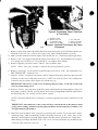
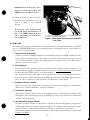
\ -
DATE: 5/8/80
CIRCULATE TO:
SERVICE MANAGER
PARTS MANAGER
MECHANICS
A.
B.
C.
D.
Steering Link Rod - 1980 Merc 40 thru l4OEL
Remote Control Repair
New Style Hydraulic Pump - Proper Filling and Vent Procedure
RPM Loss
A. STEERING LINK ROD
- 1980 Merc 40 thru 140EL
(Attach Service Bulletin Sticker on P . 7A-1 in Your C-90-86134 Service Manual.)
Should it become necessary to replace the steering link rod on a 1980 model Merc 40 thru Merc
14OEL, Ride-Guide Attaching Kit C-79278A1 must be ordered. Installation instructions are included in the kit.
B. REMOTE CONTROL REPAIR
(Attach Service Bulletin Sticker on Sec. 8 B Index Page in Your C-90-74041 Service Manual.)
Some dealers have been repairing worn electric remote controls by ordering Part No. A-45955A6
manual control and re-installing the electric harness. This control (A-45955A6) now has been
superseded to Part No. A-87728A20 which is not compatible with older electric models.
It is recommended that electric remote controls be repaired with parts available thru service
stock or order MerCruiser remote control A-45958A5.
-
C. NEW STYLE HYDRAULIC PUMP Proper Filling and Vent Procedure
(Attach Service Bulletin Sticker on P. 6-1 in Your C-90-86133 Service Manual.)
T h e initial filling and venting of the new style hydraulic pump (as used on V-6 outboards) is very
important to the operation of the trim and tilt system. Carefully follow the instructions (following) or those in the “engine mounting instructions” that accompany the outboard.
IMPORTANT: DO NOT remove “Down” port plug (Figure 1) from pump while filling trim
system.
1. Check fluid level in pump as follows:
a. Place engine in full “down” position.
b. Remove “Fill-Vent” screw (Figure 1) and wipe off dipstick with a clean, lint-free cloth.
c. Insert dipstick back into reservoir.
d. Pull dipstick from reservoir and check fluid level on stick (top line on dipstick is “Full”;
bottom line is “Add”).
-1-
f
a
b - “Down” Port Hose
- Hose Fitting Adaptor
Figure 2. Connecting “Down” Port Hose
to Trim Pump
a - “Fill-Vent’’ Screw
b - Dipstick (Top Line
on Dipstick Is “Full”;
Bottom Line is “Add”)
\A6
c - “Up” Port Hose
d - “Down” Port Plug
e - Manual Tilt Knob
Figure 1. Hydraulic Trim Pump “Up” Hose
Connected
12328
2. Remove (and retain) trim adjustment bolt from transom bracket. This will allow engine to be
trimmed to the full “in” position (necessary only when filling hydraulic system).
3. Make sure that manual tilt knob (Figure 1) is turned full “in” (clockwise, finger-tight only).
4. Remove “Up” port plug from hydraulic pump and connect “Up” port hydraulic hose (Figure
1) to pump. Be careful not to cross-thread or over-tighten hose fitting.
5. Remove shipping cap from end of “Down” port hydraulic hose.
NOTE: “Down” port plug in pump is removed after filling hydraulic system.
6. Remove “Fill-Vent” screw (Figure 1) and fill pump reservoir to “Full” line on dipstick. Use
SAE 1OW-40 “SE” automotive oil.
7. Depress “Trailer” tilt button on remote control. Engine will trim u p part-way and stop (lack
of fluid). At this time, refill pump reservoir to “Add” line (not the “Full” line) on dipstick.
Continue this procedure until engine tilts all-the-way up.
IMPORTANT: DO NOT over-fill reservoir during this procedure, or oil will overflow the
reservoir when tilting down.
8. Remove “Down” port plug from hydraulic pump and thread hose fitting adaptor (Figure 2)
into pump. Connect “Down” port hydraulic hose to hose fitting adaptor and tilt engine down
by depressing the “In” button on the remote control.
NOTE: I f the pump sounds like it is running free, and the engine does not trim in, add more oil to the
Pump.
IMPORTANT: The initial air in the system will have caused the oil in the pump to foam,
giving a false reading. Fluid level in the pump should be checked after the system has “set”
for approximately 20 minutes.
9. Bleed air from hydraulic trim system b y operating trim system 3 or 4 times thru entire
trailering range, while maintaining fluid in the pump reservoir to the “Full” line on the
dipstick. Check fluid level in pump when engine is in full “down” position (see “Important”,
immediately preceding). Reinstall “Fill-\’ent” screw. Turn screw all-the-way in and back out
1-1/2 turns (this vents the reservoir).
-2-
IMPORTANT: “Fill-Vent” screw
(Figure 3) must be backed out
1-1/2turns to vent the reservoir.
10. Check entire trim system for leaks.
11. Reinstall trim adjustment bolt (removed in Step 2 ) into transom
bracket.
If necessary, refer to the section
o n “Trim Angle Adjustments” in
the “V-6 Model Outboards Eng i n e Mounting In s t r u c t i o n s”
(C-90-88933).
a
- “Fill-Vent’’
(Turn Screw All-the-Way In and Back Out 1-1/2
Turns; This Vents the Reservoir)
Figure 3. Both Hoses Connected on Hydraulic
Trim Pump
D. RPM LOSS
Occasionally, the Mercury Marine Service Department hears customer complaints of top RPM
loss. This 300-500 RPM loss can occur suddenly and for no apparent reason. Listed below are
several causes of this problem.
1. Temperature and Humidity
Summer conditions of high temperature, low barometric pressure and high humidity all combine to reduce the engine power. This, in turn, is reflected in decreased boat speeds -- as much
as 2 or 3 miles-per-hour in some cases. Nothing but the coming of cool, dry weather will regain this speed for the boater.
2. Over-Propping
For boaters to realize optimum engine performance under changing weather conditions, it is
essential that the engine be propped to allow it to operate at or near the top end of the recommended maximum RPM range at wide-open-throttle.
Not only does this allow the engine to develop full power, but equally important is the fact
that the engine also will be operating in an RPM range that discourages damaging detonation.
This, of course, enhances overall reliability and durability of the engine.
3. Changes in Boat Condition
Scum, moss and many other forms of marine growth can develop rapidly on a boat bottom.
This can be a definite hindrance to boat performance.
4. Tachometer Incorrect
Many times, hours of labor are spent in troubleshooting a n outboard only to find that the
tachometer is not functioning properly. If RPM loss occurs, cross-reference the tachometer
with the shop tachometer.
5. Use Quicksilver Engine Cleaner
Quicksilver Engine Cleaner (C-92-86146) is a blend of chemicals designed to purge powerrobbing deposits that accumulate in gasoline engines. It eliminates costly dismantling of the
engine to remove carbon deposits that are caused by certain types of‘ gasolines.
Heavy carbon deposits in combustion chambers result in spark plug burning, pre-ignition and
reduction of RPM.
-3-