1
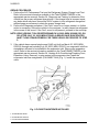
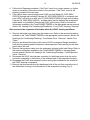
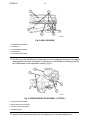
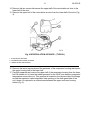
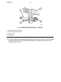
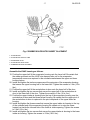
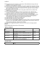
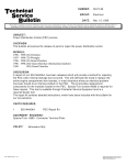
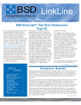
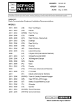
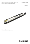
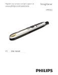
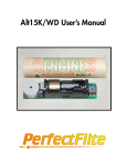
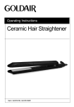
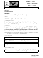
NUMBER:
GROUP:
DATE:
24-002-03
Heating and A/C
Apr. 4, 2003
This bulletin is supplied as technical information only and is not an authorization for repair. No part of this publication may be reproduced, stored in a retreival system,
or transmitted, in any form or by any means, electronic, mechanical, photocopying, or otherwise, without written permission of DaimlerChrysler Corporation.
SUBJECT:
Evaporator Hiss Sound
OVERVIEW:
This bulletin involves installing an evaporator inlet flow straightener and a rubber
evaporator insert between the evaporator tubes if necessary.
MODELS:
2002 - 2003
(RS)
Town & Country/Caravan/Voyager
SYMPTOM/CONDITION:
Some customers may experience a "hiss" sound, that originates from the Heating,
Ventilation, Air Conditioning (HVAC) unit. This may be most noticeable when operating
between 18° C - 27° C (65° F - 80° F).
DIAGNOSIS:
Operate the vehicle in a moderate ambient temperature, 18° C - 27° C (65° F - 80° F). Run
the HVAC system in recirculation, panel mode, A/C off, full heat, high blower for 1 to 2
minutes to heat the evaporator. Switch the HVAC system to outside air, panel mode, A/C
on, full cool, low blower, and maintain a steady engine speed of approximately 2000 rpm.
Listen for a "hiss" that will occur when the A/C clutch cycles on.
NOTE: PERFORM THIS PROCEDURE AFTER EACH REPAIR TO THE HVAC SYSTEM,
TO VERIFY THE “HISS” IS NO LONGER PRESENT.
PARTS REQUIRED:
Qty.
Part No.
Description
AR (1)
04885713AA
Flow Straightener, Evaporator Inlet
AR (1)
05061454AA
Rubber Evaporator Insert
AR (1)
05019220AD
Seal Kit, A/C and Heater Unit
AR (2.69
lbs., 43
oz.)
Refrigerant R134A
EQUIPMENT REQUIRED:
NPN
Refrigerant Recovery/Recycling Station - Models Available
through Pentastar Service Equipment
24-002-03
-2-
REPAIR PROCEDURE:
1. Perform the A/C Performance Test and the Refrigerant System Charge Level Test.
Refer to the service information available in the TechCONNECT/MDS2 or the
appropriate service manual, Section 24, Diagnosis and Testing, to determine if the
vehicle has the proper refrigerant charge level. If the charge level is incorrect repair
any leaks which may have caused the HVAC system to lose refrigerant charge and
add/recharge as necessary to attain the proper charge level.
2. Perform the Diagnosis procedure. If the "hiss" sound is no longer present, no further
action is necessary. Return the vehicle to the customer. In many cases low refrigerant
is the cause of this sound. If the “hiss” sound is still present, proceed to the next step.
NOTE: VEHICLES BUILT ON OR BEFORE MARCH 24, 2002 (MDH 0324XX) OR, ON
OR AFTER JULY 22, 2002 (MDH 0722XX) ALREADY HAVE EVAPORATOR
INLET FLOW STRAIGHTENERS. FOR THESE VEHICLES PROCEED TO STEP
5.
3. If the vehicle has a manual single zone HVAC unit built on March 25, 2002 (MDH
0325XX) through and including July 22, 2002 (MDH 0722XX), an evaporator inlet flow
straightener will need to be installed in the evaporator inlet. Remove the expansion
valve. Refer to the service information available in the TechCONNECT/MDS2 or the
appropriate service manual, Section 24, Heating & Air Conditioning/Plumbing Front,
Expansion Valve, Removal, to gain access to the evaporator inlet. Install the
evaporator inlet flow straightener (P/N 04885713AA) (Fig. 1). Install the expansion
valve.
Fig. 1 FLOW STRAIGHTENER INSTALLED
1 - EVAPORATOR INLET
2 - EVAPORATOR OUTLET
3 - FLOW STRAIGHTENER
-3-
24-002-03
4. Perform the Diagnosis procedure. If the "hiss" sound is no longer present, no further
action is necessary. Return the vehicle to the customer. If the “hiss” sound is still
present, proceed to the next step.
5. If the vehicle has a manual single zone HVAC unit built March 25, 2002 (MDH
0325XX) through and including February 26, 2003 (MDH 0226XX) or a manual dual
zone HVAC unit built on or after July 22, 2002 (MDH 0722XX) through and including
February 26, 2003 (MDH 0226XX) , a rubber insert that fits between the evaporator
tubes needs to be installed. Remove the HVAC unit housing. Refer to the service
information available in the TechCONNECT/MDS2 or the appropriate service manual,
Section 24, Heating & Air Conditioning/Distribution - Front, HVAC Housing, Removal.
Gain access to the evaporator inlet tubes within the HVAC housing as follows:
6. Remove the heater core tubes from the heater core. Refer to the service information
available in the TechCONNECT/MDS2 or the appropriate service manual, Section 24,
Heating & Air Conditioning/Plumbing - Front/Heater Core - Removal - Heater Core
Tubes.
7. Remove and discard the foam seal from the HVAC housing seal flange around the
fresh air inlet opening and the expansion valve/evaporator tube opening on the dash
panel side of the unit.
8. Remove the expansion valve from the evaporator inlet and outlet tube fittings. Refer to
the service information available in the TechCONNECT/MDS2 or the appropriate
service manual, Section 24, Heating & Air Conditioning/Plumbing - Front/Expansion
Valve - Removal
9. Disconnect the HVAC wire harness connector for the blower motor from the motor
connector receptacle on the bottom of the outboard end of the evaporator housing.
10. Disengage the HVAC wire harness from the routing clips molded into the outside of
the HVAC housing components.
11. Remove the three screws from the dash panel side of the unit that secure the top of
the distribution housing to the inboard end of the evaporator housing (Fig. 2).
24-002-03
-4-
Fig. 2 HVAC HOUSING
1 - DISTRIBUTION HOUSING
2 - SCREWS (3)
3 - HVAC WIRING HARNESS
4 - ROUTING CLIP
5 - EVAPORATOR HOUSING
12. Pull the top of the distribution housing away from the evaporator housing far enough to
disengage the two hook formations on the bottom of the distribution housing from the
two receptacles on the evaporator housing (Fig. 3).
Fig. 3 UPPER INTAKE AIR HOUSING - (TYPICAL)
1 - EVAPORATOR HOUSING
2- UPPER INTAKE AIR HOUSING
3 - RECIRCULATION AIR DOOR
4 - BLOWER WHEEL
13. Remove the screw and washer from the upper pivot of the recirculation door.
-5-
24-002-03
14. Remove the two screws that secure the upper half of the recirculation air door to the
lower half of the door.
15. Remove the upper half of the recirculation air door from the lower half of the door (Fig.
4).
Fig. 4 RECIRCULATION AIR DOOR - (TYPICAL)
1 - EVAPORATOR HOUSING
2 - UPPER RECIRCULATION AIR DOOR
3 - LOWER INTAKE AIR HOUSING
16. Remove the twelve screws around the perimeter of the evaporator housing that secure
the upper housing half to the lower half.
17. Carefully separate and remove the upper half of the evaporator housing from the lower
half. Be certain not to loose the rubber grommet for the HVAC wire harness evaporator
temperature sensor take out. This grommet is located on the inboard side of the flange
around the expansion valve/evaporator tube opening on the dash panel side of the
unit, where it is captured in a notched area between the upper and lower housing
halves (Fig. 5).
24-002-03
-6-
Fig. 5 EVAPORATOR HOUSING - (TYPICAL)
1 - LOWER EVAPORATOR HOUSING
2 - UPPER EVAPORATOR HOUSING
3 - BLOWER WHEEL
4 - EVAPORATOR
18. With the evaporator assembly removed from the evaporator housing, install the rubber
evaporator tube insert (p/n 05061454AA) between the evaporator inlet and outlet
tubes as shown (Fig. 5).
-7-
24-002-03
Fig. 6 RUBBER EVAPORATOR INSERT PLACEMENT
1 - EVAPORATOR
2 - EVAPORATOR OUTLET TUBE
3 - EXPANSION VALVE
4 - EVAPORATOR INLET TUBE
5 - RUBBER EVAPORATOR INSERT
Assemble the HVAC housing as follows:
19. Position the upper half of the evaporator housing onto the lower half. Be certain that
the rubber grommet and the HVAC wire harness take out for the evaporator
temperature sensor are captured in the notched area between the upper and lower
housing halves.
20. Install and tighten the twelve screws around the perimeter of the evaporator housing
that secure the upper housing half to the lower half. Tighten the screws to 2 Nm (18 in.
lbs.).
21. Position the upper half of the recirculation air door onto the lower half of the door.
22. Install and tighten the two screws that secure the upper half of the recirculation air
door to the lower half of the door. Tighten the screws to 2 Nm (18 in. lbs.).
23. Position the upper intake air housing onto the top of the evaporator housing over the
recirculation air door and the blower wheel housing. Be certain that the upper pivot of
the recirculation air door is captured in the pivot receptacle of the upper intake air
housing.
24. Install and tighten the three screws that secure the upper intake air housing to the top
of the outboard end of the evaporator housing. Be certain not to miss the screw
located just inside the inboard side of the fresh air intake opening. Tighten the screws
to 2 Nm (18 in. lbs.).
25. Install and tighten the two screws that secure the upper intake air housing to the lower
intake air housing. Tighten the screws to 2 Nm (18 in. lbs.).
24-002-03
-8-
26. Engage the two hook formations on the bottom of the distribution housing in the two
receptacles on the evaporator housing.
27. Roll the top of the distribution housing up into position against the evaporator housing.
28. Install and tighten the three screws from the dash panel side of the unit that secure the
top of the distribution housing to the inboard end of the evaporator housing. Tighten
the screws to 2 Nm (18 in. lbs.).
29. Engage the HVAC wire harness in the routing clips molded into the outside of the
HVAC housing components.
30. Connect the HVAC wire harness connector for the blower motor with the motor
connector receptacle on the bottom of the outboard end of the evaporator housing.
31. Install the expansion valve onto the evaporator inlet and outlet tube fittings.
32. Install a new foam seal from the A/C Heater unit seal kit (p/n 05019220AD) onto the
HVAC housing seal flange around the fresh air inlet opening and the expansion
valve/evaporator tube opening on the dash panel side of the unit.
33. Install the heater core tubes into the heater core.
34. Install the HVAC unit housing into the vehicle.
35. Run the HVAC Control Actuator Calibration procedure. Refer to the service information
available in the TechCONNECT/MDS2 or the appropriate service manual, Section 24 Heating & Air Conditioning - Diagnosis And Testing.
36. Perform the Diagnosis procedure to insure the “hiss” sound is no longer present.
POLICY:
Reimbursable within the provisions of the warranty.
TIME ALLOWANCE:
Labor Operation
No:
Description
Amount
24-65-02-90
Performance Test A/C System
0.6 Hrs.
24-65-02-91
Performance Test A/C System and Install Flow
Straightener
1.0 Hrs.
24-65-02-92
Performance Test A/C System and Install A/C
Coil Isolator
4.1 Hrs
24-65-02-93
Performance Test A/C System and Install A/C
Coil Isolator and Flow Straightener
4.5 Hrs
FAILURE CODE:
68
Noisy