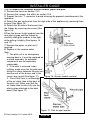
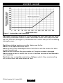
1
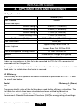
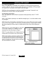
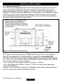
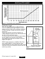
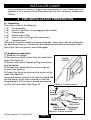
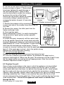
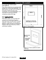
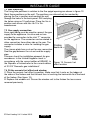
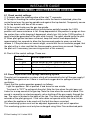
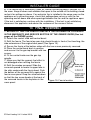
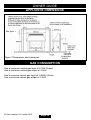
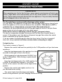
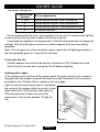
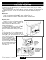
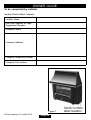
600B690/15 INSTALLATION AND OWNER GUIDE Model 341 Black Beauty Slimline LIVE FUEL EFFECT GAS FIRE (GC No. 32-032-30) We trust that this guide gives sufficient details to enable this appliance to be installed and maintained satisfactorily. However, if further information is required, our Valor Fires Technical Helpline will be pleased to help. Telephone 0844 8711 565 (National call rates apply in the United Kingdom). In the Republic of Ireland Telephone 0044 844 8711 565. INSTALLER: Please leave this guide with the owner © Baxi Heating U.K. Limited 2010. THIS APPLIANCE IS FOR USE WITH NATURAL GAS (G20). UNDER NO CIRCUMSTANCES IS THIS FIRE TO BE CONVERTED TO LPG. AN LPG KIT DOES NOT EXIST FOR THIS GAS FIRE. THIS APPLIANCE IS SUITABLE ONLY FOR INSTALLATION IN THE UNITED KINGDOM (GB) AND THE REPUBLIC OF IRELAND (IE). Baxi Heating U.K. Limited 2010. All rights reserved. No part of this publication may be reproduced in any material form (including photocopying), stored in any medium by electronic means (including in any retrieval system or database) or transmitted, in any form or by any means, whether electronic, mechanical, recording or otherwise, without the prior written permission of the copyright owner. Applications for the copyright owner's permission to reproduce any part of this publication should be made, giving details of the proposed use, to the following address: The Company Secretary, Baxi Heating UK Limited, Brooks House, Coventry Road, Warwick, CV34 4LL. Warning: Any person who does any unauthorised act in relation to a copyright work may be liable to criminal prosecution and civil claims for damages. Valor Fires, Erdington, Birmingham B24 9QP www.firesandstoves.co.uk Because our policy is one of constant development and improvement, details may vary slightly from those given in this publication © Baxi Heating U.K. Limited 2010. Page 2 Safety First. Valor Fires fires are CE Approved and designed to meet the appropriate British Standards and Safety Marks. Quality and Excellence. All Valor Fires fires are manufactured to the highest standards of quality and excellence and are manufactured under a BS EN ISO 9001 quality system accepted by the British Standards Institute. The Highest Standards Valor Fires is a member of SBGI and HHIC (Heating and Hot water Industry Council) that work to ensure high standards of safety, quality and performance. Careful Installation This gas fire must be installed by a competent GAS SAFE REGISTER engineer (CORGI or GAS SAFE REGISTER engineer outside of UK) in accordance with our installer guide and should not be fitted directly on to a carpet or floor of combustible material. © Baxi Heating U.K. Limited 2010. Page 3 INSTALLER GUIDE INSTALLER GUIDE FOR OWNER GUIDE SEE PAGES 30 TO 43 © Baxi Heating U.K. Limited 2010. Page 4 INSTALLER GUIDE CONTENTS Section Heading Page INSTALLER GUIDE OWNER GUIDE 4 - 29 30 - 43 1. 2. 3. 4. 6 7 7 8 8 8 9 9 10 10 10 11 11 12 13 14 14 14 14 15 16 16 17 17 17 18 19 19 20 20 20 21 21 21 IMAGE SAFETY LIST OF ACCESSORIES APPLIANCE DATA AND EFFICIENCY 4.1 Appliance data. 4.2 Efficiency. 5. GENERAL INSTALLATION REQUIREMENTS 5.1 Regulations, Standards and Law. 5.2 Ventilation. 5.3 The Atmosphere sensing device (ASD). 5.4 Room considerations. 5.5 Chimney preparation. 5.6 Fireplace preparation. 5.7 Fireplace clearances. 5.8 The Flue spigot. 5.9. The hearth. 5.10 Installation options. 5.10.1 Conventional fireplace. 5.10.2 Precast flues. 5.10.3 Wall mounting to conventional or pre-cast flues. 5.10.4 Metal flue box. 5.11 Flues. 6. PRE-INSTALLATION PREPARATION 6.1 Unpacking. 6.2 Appliance preparation. 6.3 Fireplace flue pull. 6.4 Fitting the closure plate. 6.4.1 Hearth mounting 6.4.2 Wall mounting 7. APPLIANCE INSTALLATION 7.1 Installing to a hearth. 7.2 Wall mounting. 7.3 Gas supply connection. 7.4 Fit the ceramic fuel effect and window. Continued on next page © Baxi Heating U.K. Limited 2010. Page 5 INSTALLER GUIDE CONTENTS (Continued) Section Heading Page 8. CONTROL AND PRESSURE CHECKS 8.1 Check control settings. 8.2 Flame supervision and spillage monitoring system. 8.3 Check burner pressure. 9. SPILLAGE CHECK 10. FINAL ASSEMBLY 11. FINAL REVIEW 12. SERVICING AND PARTS REPLACEMENT 12.1 To remove the window unit. 12.2 To remove the fascia. 12.3 To remove the ceramic fuel effect. 12.4 To remove the gas tap. 12.5 To remove the piezo generator. 12.6 To grease the control tap. 12.7 To remove an injector. 12.8 To remove the complete burner module, pipes and pilot. 1. IMAGE © Baxi Heating U.K. Limited 2010. Page 6 22 22 22 23 23 24 25 26 27 27 27 27 28 28 28 29 INSTALLER GUIDE 2. SAFETY Installer Before continuing any further with the installation of this appliance please read the following guide to manual handling: The lifting weight of this appliance is 16.86 kg. One person should be sufficient to lift the fire. If for any reason this weight is considered too heavy then obtain assistance. When lifting always keep your back straight. Bend your legs and not your back. Avoid twisting at the waist. It is better to reposition your feet. Avoid upper body / top heavy bending. Do not lean forward or sideways whilst handling the fire. Always grip with the palm of the hand. Do not use the tips of fingers for support. Always keep the fire as close to the body as possible. This will minimise the cantilever action. Use gloves to provide additional grip. Always use assistance if required. This product uses a fuel effect and gaskets containing Refractory Ceramic Fibres (RCF), which are man-made vitreous silicate fibres. Excessive exposure to these materials may cause irritation to eyes, skin and respiratory tract. Consequently, it is important to take care when handling these articles to ensure that the release of dust is kept to a minimum. To ensure that the release of fibres from these RCF articles is kept to a minimum, during installation and servicing we recommend that you use a HEPA filtered vacuum to remove any dust and soot accumulated in and around the fire before and after working on the fire. When replacing these articles we recommend that the replaced items are not broken up, but are sealed within a heavy duty polythene bag, clearly labelled as RCF waste. RCF waste is classed as a stable, non-reactive hazardous waste and may be disposed at a landfill licensed to accept such waste. Protective clothing is not required when handling these articles, but we recommend you follow the normal hygiene rules of not smoking, eating or drinking in the work area and always wash your hands before eating or drinking. This appliance does not contain any component manufactured from asbestos or asbestos related products. 3. LIST OF ACCESSORIES Description Spigot extension © Baxi Heating U.K. Limited 2010. Part number 0595191 Page 7 INSTALLER GUIDE 4. APPLIANCE DATA AND EFFICIENCY 4.1 Appliance data. Gas Natural (G20) Inlet Pressure 20mbar Gross Heat Input Control Setting 4 5.05kW (17,200Btu/h) Control Setting 3 3.45kW (11,800Btu/h) Control Setting 2 1.80kW (6,100Btu/h) Control Setting 1/IGN 1.55kW (5,300Btu/h) Burner Test Pressure (Cold) 17.2 + 0.75mbar (6.9 + 0.3in w.g.) Gas Connection 8mm pipe Upper - Bray Cat. 99 Size 115 Burner Injectors Lower - Bray Cat. 99 Size 230A Pilot & Atmosphere Sensing Device SIT Ref. OPNG9419 Ignition Piezo-electric integral with gas tap Aeration Non-adjustable Under no circumstances is this fire to be converted to LPG. An LPG conversion kit does not exist for this gas fire. The appliance information label is on the inner face of the back panel at the lower left hand side. It is visible when the fascia is removed. 4.2 Efficiency. The efficiency of this appliance has been measured as specified in BS 7977 - 1 and the result is as below : Model 341 Efficiency % (Gross) 79 The gross calorific value of the fuel has been used for this efficiency calculation. The test data from which it has been calculated has been certified by Advantica Certification services (0087). The efficiency value may be used in the UK Government's Standard Assessment Procedure (SAP) for energy rating of dwellings. © Baxi Heating U.K. Limited 2010. Page 8 INSTALLER GUIDE The convertion of net efficiency to gross was achieved by multiplying the net efficiency by the following conversion factor from Table E3 of SAP 2005, rounding down to the nearest whole number. Gas Conversion factor from net to gross efficiency Natural Gas 0.901 5. GENERAL INSTALLATION REQUIREMENTS 5.1 Regulations, Standards and Law. The installation must be in accordance with these instructions. For the user’s protection, in the United Kingdom it is the law that all gas appliances are installed by competent persons in accordance with the current edition of the Gas Safety (Installation and Use) Regulations. Failure to install the appliance correctly could lead to prosecution. GAS SAFE REGISTER and CORGI require their members to work to recognised standards. In the United Kingdom the installation must also be in accordance with: All the relevant parts of local regulations. All relevant codes of practice. The relevant parts of the current editions of the following British Standards:BS 715 Specification for metal flue boxes for gas-fired appliances not exceeding 20kW. BS EN 1806 Chimneys – Clay/ceramic flue blocks. BS 5440 Part 1 Flueing and ventilation for gas appliances of rated input not exceeding 70 kW net (1st, 2nd and 3rd family gases). Specification for installation of gas appliances to chimneys and for maintenance of chimneys. BS 5440 Part 2 Installation and maintenance of flues and ventilation for gas appliances of rated input not exceeding 70 kW net (1st, 2nd and 3rd family gases). BS 6891 Installation of low pressure gas pipework of up to 35mm (R1 ¼) in domestic premises (2nd family gas) - specification. BS 1251 Fireplace components. BS EN 1856 Part 1 - Chimneys – Requirements for metal chimneys. BS 5871 Part 1 Specification for the installation and maintenance of gas fires, convector heaters, fire/back boilers and decorative fuel effect gas appliances. Gas fires, convector heaters, fire/back boilers and heating stoves (2nd and 3rd family gases). BS EN 1858 Chimneys – Components – Concrete flue blocks. BS EN 15287 Part 1 - Chimneys. Design, installation and commissioning of chimneys. Chimneys for non-room sealed heating appliances. In England and Wales, the current edition of the Building Regulations issued by the Department of the Environment and the Welsh Office. © Baxi Heating U.K. Limited 2010. Page 9 INSTALLER GUIDE In Scotland, the current edition of the Building Standards (Scotland) Regulations issued by the Scottish Executive. In Northern Ireland, the current edition of the Building regulations (Northern Ireland) issued by the Department of the Environment for Northern Ireland. In the Republic of Ireland the installation must be carried out by a competent person and installed in accordance with: a) The current edition of IS 813 “Domestic gas installations”. b) All relevant national and local rules in force. c) The current building regulations Where no specific instructions are given, reference should be made to the relevant British Standard Code of Practice. 5.2 Ventilation. Normal adventitious ventilation is usually sufficient to satisfy the ventilation requirements of this appliance. In GB reference should be made to BS 5871 Part 2 and in IE reference should be made to the current edition of IS 813 “Domestic gas Installations” which makes clear the conditions that must be met to demonstrate that sufficient ventilation is available. 5.3 The Atmosphere sensing device (ASD). The appliance is fitted with an A.S.D (Atmosphere sensing device). If the appliance closes down after a period of operation for no apparent reason, the consumer should be informed to stop using the appliance until the installation and appliance have been thoroughly checked. The A.S.D will shut the appliance down if an unacceptable amount of harmful products of combustion accumulate. Under no circumstances should the A.S.D be altered or bypassed in any way. Only genuine manufacturer’s replacement parts should be fitted. 5.4 Room considerations. 5.4.1 The appliance must not be installed in any room that contains a bath, shower or where steam is regularly present. 5.4.2 An extractor fan may only be used in the same room as this appliance, or in any area from which ventilation for the appliance is taken, if it does not affect the safe performance of the appliance. Note the spillage test requirements detailed further on in this manual. If the fan is likely to affect the appliance, the appliance must not be installed unless the fan is permanently disconnected. 5.4.3 Note that soft wall coverings (e.g. embossed vinyl, etc.) are easily affected by heat. They may scorch or become discoloured when close to a heating appliance. Please bear this in mind when installing. © Baxi Heating U.K. Limited 2010. Page 10 INSTALLER GUIDE 5.5 Chimney preparation. 5.5.1 If the appliance is intended to be installed to a chimney that was previously used for solid fuel, the flue must be swept clean prior to installation. All flues should be inspected for soundness and freedom from blockages. 5.5.2 Any chimney dampers or restrictors should be removed. If removal is not possible they must be fixed in the open position. 5.6 Fireplace preparation. 5.6.1 The appliance can be fitted to a purpose made proprietary class “O” 150°C surround. 5.6.2 If the fireplace opening is an underfloor draught type, it must be sealed to stop any draughts. 5.6.3 The front of the fireplace should be flat over an area sufficient to ensure a good seal with the closure plate. The flat surface should extend for a height equal to that of the closure plate plus 20mm and for a width equal to that of the closure plate plus 40mm. 5.6.4 If the fire is to be fitted against a wall with combustible cladding, the cladding must be removed from the area shown in figure 1. 5.6.5 The space between the fireplace front face and the back of the fascia must not be filled in. 5.6.6 If the fireplace opening is greater than the acceptable dimensions given in this guide, do not use the back of a fire surround or marble to reduce the opening. This may cause cracking of the surround back or marble. Figure 1. Area to be free of combustible cladding © Baxi Heating U.K. Limited 2010. Page 11 INSTALLER GUIDE 5.7 Fireplace clearances. 5.7.1 The minimum allowable distance from the outside of the appliance fascia to a corner wall having combustible material or any other combustible surface which projects beyond the front of the appliance is 100mm at either side (See figure 2). A clearance of 100mm should be maintained at the right side in all installations to allow satisfactory access to the control knob. Although no side clearance is necessary to non-combustible surfaces on the left hand side we recommend a 100mm clearance for service access to the fascia side fixings. Figure 2. Dimensions and clearances 5.7.2 Allow a minimum clearance of 150mm from the top surface of the appliance fascia to the underside of any shelf whether it is made from non-combustible materials. This clearance is necessary to allow the fascia to be lifted off for servicing. For a shelf made from wood or other combustible materials deeper than 150mm, the minimum clearance must be as below. • For a shelf up to 150mm deep: Minimum clearance = 150mm. • For a shelf deeper than 150mm: 150mm + 12.5mm for every 25mm depth over 150mm (See figure 3). Important : No combustible material (e.g. Wallpaper, plastic tiling, wood panelling etc.) must be used on the fireplace wall below the shelf. © Baxi Heating U.K. Limited 2010. Page 12 INSTALLER GUIDE Figure 3. Combustible shelf clearances 5.8 The Flue spigot. 5.8.1 The flue spigot and any spigot extension must be capable of passing through the closure plate by at least 15mm with a minimum clearance of 50mm between its open end and the nearest obstruction. There must also be a minimum clearance of 165mm between the back of the closure plate and the back of the catchment space. On conventional flues the catchment space below the flue spigot must extend at least 250mm downward measured from the bottom of the flue spigot (See figure 4). 5.8.2 A spigot extension is available (Valor Fires part number 0595191). When fitted this shall extend through the closure plate for at least 15mm and have a minimum clearance of 50mm from the Figure 4. Fireplace catchment end to any surface. space. © Baxi Heating U.K. Limited 2010. Page 13 INSTALLER GUIDE 5.9. The hearth. The appliance must be mounted on a non-combustible hearth except when the conditions in section 5.10.3 are met (N.B. conglomerate marble hearths are considered as non-combustible). The hearth must be at least 680mm wide x 300mm deep. The hearth material must be at least 12mm thick. The periphery of the hearth (or fender) should be at least 50mm above floor level to discourage the placing of carpets or rugs over it. 5.10 Installation options. In the United Kingdom, as supplied, this appliance can be installed in the following situations: 5.10.1 Conventional fireplace. The fireplace opening must be within the following dimensions: Width Max. Min. Height 432mm 305mm Max. Min. 610mm* 550mm *The total height of the closure plate is 660mm and will accommodate a maximum opening height of 650mm (This allows a 10mm overhang). Heights above 635mm (Inclusive of sealing tape) will leave the sealing tape and closure plate visible above the appliance. 5.10.2 Precast flues. The appliance can be installed to a fireplace that has a properly constructed precast concrete or clay flue block system conforming to BS1289 or BS EN 1806. The appliance is suitable for installations conforming to older versions of BS1289 as well as the current standards. The flue blocks must have a minimum width not less than 63mm and a cross-sectional area not less than 13,000mm2. Older editions of BS1289 required a cross-sectional area of 13,000mm2. The current revision of the standard requires 16,500mm2. This appliance is suitable in both cases. The chimney should be one or two storey high but not less than 3m vertical height and be correctly terminated. No mortar fangs between the blocks should be extruded into the flueway. If raking blocks are used, they must be fitted in accordance with the manufacturer’s instructions. Mortar must not be allowed to drop down and accumulate in the raked positions. © Baxi Heating U.K. Limited 2010. Page 14 INSTALLER GUIDE The fireplace opening must be within the following dimensions: Width Max. Min. Height 432mm 305mm Max. Min. 610mm1 550mm2 1 The total height of the closure plate is 660mm and will accommodate a maximum opening height of 650mm (This allows a 10mm overhang). Heights above 635mm (Inclusive of sealing tape) will leave the sealing tape and closure plate visible above the appliance. 2 Any opening visible below the appliance may be closed in. 5.10.3 Wall mounting to conventional or pre-cast flues. The wall opening must be within the following dimensions: Width Max. Min. Height 432mm 305mm Max. Min. 610mm* 334mm *The total height of the closure plate is 660mm and will accommodate a maximum opening height of 650mm (This allows a 10mm overhang). Heights above 635mm (Inclusive of sealing tape) will leave the sealing tape and closure plate visible above the appliance. The bottom of the appliance must be at least 100mm above the finished floor covering (See figure 2). This requires the top of the opening to be at least 650mm above the finished floor covering. Any opening visible below the appliance may be closed in but the depth of the catchment space within the wall opening must be as shown in figure 4. © Baxi Heating U.K. Limited 2010. Page 15 INSTALLER GUIDE 5.10.4 Metal flue box. The appliance can be installed to a metal flue box conforming to BS715 with a minimum internal depth of 200mm. Incombustible mineral wool insulation of not less than 50mm thickness must be applied to the top surface of the firebox and it must stand on a non combustible hearth. There must be an air gap clearance of 50mm all round the outside of the box and above the top insulation to any combustible material. The opening must be within the following dimensions: Width Max. Min. Height 432mm 407mm Max. Min. 610mm* 560mm** * The total height of the closure plate is 660mm and will accommodate a maximum opening height of 650mm (This allows a 10mm overhang). Heights above 635mm (Inclusive of sealing tape) will leave the sealing tape and closure plate visible above the appliance. ** This fire has been tested for use on the ‘Rite-Vent’ 7T95125 metal flue box and found to be satisfactory. 5.11 Flues. 225mm x 225mm conventional brick flue. If a flue liner is used, it must be a minimum of 125mm diameter. The liner must be sealed to the surrounding area above the fireplace opening and to the top of the chimney. An approved terminal must be fitted. A properly constructed precast flue conforming to BS EN 1806, BS EN 1858 or B.S 1289. A flue pipe with a minimum diameter of 127mm. See BS EN 15287-1 for suitable materials. Metal flue pipes must comply with BS EN 1856 part 1. See section 5.10.4 of this guide for flue box opening sizes. The flue must conform to BS 5440: Part 1 in design and installation. The flue, measured from the bottom of the fireplace opening to the bottom of the terminal, shall be not less than 3m in actual vertical height. When calculated in accordance with BS 5440: Part 1 Annex B, the minimum equivalent height of the flue shall be 2.0m of 125mm dia. flue pipe. The flue must be clear of any obstruction and its base must be clear of debris. The flue must be completely sealed so that combustion products do not come into contact with combustible materials outside the chimney. The flue must serve only one fireplace. Proprietary terminals must comply with BS EN 1858, BS EN 1806 or BS 1289 and older versions of BS 715. Any terminal or termination must be positioned in accordance with BS 5440 Part 1 to ensure that the products of combustion can be safely dispersed into the outside atmosphere. Where the appliance is connected © Baxi Heating U.K. Limited 2010. Page 16 INSTALLER GUIDE to an unlined brick chimney it is generally unnecessary for the chimney pot to be replaced or for a terminal to be fitted unless the flue has a diameter smaller than 170mm. 6. PRE-INSTALLATION PREPARATION 6.1 Unpacking. The carton contains the following:1 off Fire assembly. 1 off Ceramic fuel effect (In packaging inside firebox). 1 off Closure plate. 1 off Smoke match tube. 1 off Olive & olive nut for gas line connection 1 off Literature pack Remove all the items carefully to prevent damage. Some items may be contained in the packaging fitments - Examine the packaging carefully before discarding. Check that all the items are present and undamaged. 6.2 Appliance preparation. 1. Stand the fire upright. 2. Remove two transit screws from the upper back panel (See figure 5). 3. Remove the control knob by pulling clear of the gas tap spindle. 4. Remove the control bezel by unscrewing two screws (See figure 6). 5. Detach the fascia by removing the screws at the sides (See figure 6). Spring the bottom corners of the fascia outward and pull the bottom of the fascia forward to clear the fixing brackets. Lift the fascia upward and forward Figure 5. Transit screws. to clear the top location (See figure 6). Figure 6. Fascia removal. © Baxi Heating U.K. Limited 2010. Page 17 INSTALLER GUIDE 6. The front of the fascia is secured by two screws as shown in figure 7. These screws have been tightened to avoid damage to the fascia during transit. These screws must be slackened to enable the customer to remove this section of the fascia. Slacken the two screws, detach the window surround by sliding it upward and then swinging the bottom forward. Lift and store carefully. Figure 7. Window surround removal. 7. Remove the window unit by removing the screws each side of the window frame and lifting the unit clear. 8. Remove the ceramic fuel effect pack from the firebox and keep it safe. 9. Check ignition spark. Before attempting to install, it is worth checking that the piezo electric spark ignition system operates satisfactorily. To initiate the spark, temporarily refit the control knob to the tap spindle. Depress the control knob and while keeping it depressed, slowly turn anticlockwise through approximately 60° to the 1/IGN position. A spark should Figure 8. Pilot spark gap track from the electrode pin to pilot burner. If there is no spark or incorrect tracking, check that the spark gap is between the limits shown in figure 8. If the spark gap is correct, check the ignition wiring. Remove the control knob after checking. 10. For wall mounted appliances. Remove the levelling screws and locknuts from below the feet. 11. If the fire is fitted to a recessed fireplace, an extension flue spigot up to a maximum total length of 125mm may be used. The extension must be a tight fit over the flue spigot and be secured by two self tapping screws. Note the minimum clearance required as shown in figure 4. 6.3 Fireplace flue pull. Close all doors and windows in the room in which the appliance is to be installed. After confirming with a match that smoke is drawn into the flue, light a 13 gram smoke pellet and check that there is a definite flow through the flue. Verify outside that the smoke exits from one terminal only and that the termination is suitable. Observe, where possible, upstairs rooms and loft spaces for signs of escaping smoke indicating a defective flue. If there is not a definite flow warm the flue for a few minutes and repeat the smoke pellet test. If there is still no definite flow the flue may need remedial work – Do not fit the appliance until there is a definite flow through the flue. © Baxi Heating U.K. Limited 2010. Page 18 INSTALLER GUIDE 6.4 Fitting the closure plate. (See figure 9). The closure plate has an opening at the bottom for a central gas feed pipe. The gap between the pipe and this opening should be sealed with tape after connection. If a central feed pipe is not required the opening should be completely sealed with tape. 6.4.1 Hearth mounting (See figure 10). The closure plate must be fitted and sealed to the hearth and fireplace opening using a suitable heat resistant material. If necessary cut the closure plate but make sure that it overlaps the fireplace opening sufficiently to allow satisfactory sealing. Figure 9. Closure plate. Figure 10. Closure plate for hearth mounting. © Baxi Heating U.K. Limited 2010. Page 19 INSTALLER GUIDE 6.4.2 Wall mounting (See figure 11). The closure plate must be fitted and sealed to the hearth and fireplace opening using a suitable heat resistant material. If necessary cut the closure plate but make sure that it overlaps the fireplace opening sufficiently to allow satisfactory sealing. The bottom of the appliance must be at least 100mm above any carpet or other floor covering. To achieve this, the bottom of the flue spigot opening must be at least 565mm above the finished floor covering. 6.4.3 Check the flue pull with Figure 11. Closure plate for wall mounting. closure plate fitted by applying a lighted match or smoke match to the flue spigot opening in the closure plate and observe the smoke. If there is a definite flow continue with the installation. If not check the fitting of the closure plate. The fireplace flue pull check described in section 6.3 should have confirmed that the fireplace itself is satisfactory. 7. APPLIANCE INSTALLATION 7.1 Installing to a hearth. 1. Place the fire centrally on the hearth making sure that the spigot lines up with the spigot hole in the closure plate. Gently slide the appliance into place being careful not to scratch the hearth. The spigot must enter the closure plate to a depth of at least 15mm. 2. Level the fire by loosening the lock nuts and turning the levelling screws in the feet up or down as required while they bear on the hearth. When the fire is level and square to the wall, retighten the lock nuts. Figure 12. Wall fixing holes © Baxi Heating U.K. Limited 2010. Page 20 INSTALLER GUIDE 7.2 Wall mounting. The fixing hole positions in relation to the flue spigot opening are shown in figure 12. Mark these positions on the wall. The positions can alternatively be marked by placing the fire in position and marking the wall through the holes in the back panel. Drill and plug the holes using no.10 wall plugs. Place the fire in position and secure with four no.10 x 2in. woodscrews. 7.3 Gas supply connection. 8mm rigid tubing must be used to connect the gas supply to the appliance. An olive and nut are provided for connection to the inlet “T” connector on the appliance. The connector can be rotated to allow connection from either side or the rear. The connector includes a valve for isolating the gas supply. The closure plate has a cut-out for rear connection. Seal the gap between the cut-out and the supply pipe. Pressure check the installation pipework for gas soundness. In the United Kingdom check in accordance with the current edition of BS6891. In Figure 13. Ceramic fuel the Republic of Ireland refer to the current edition effect location of IS 813 “Domestic gas installations”. 7.4 Fit the ceramic fuel effect and window. 1. Place the ceramic fuel effect in position. Make sure that it rests on the ledges at the sides of the firebox and that its back face is touching the horizontal rib at the back of the firebox (See figure 13). 2. Replace the window unit. Secure the window unit to the firebox the two screws removed previously. © Baxi Heating U.K. Limited 2010. Page 21 INSTALLER GUIDE 8. CONTROL AND PRESSURE CHECKS 8.1 Check control settings. 1. If closed, open the isolating valve at the inlet ‘T’ connector. 2. To help in checking the control positions while the fascia is detached, place the control bezel over the gas tap spindle and against the tap bracket. Temporarily secure to the tap bracket with one of the screws. 3. Fit the control knob over the gas tap spindle. 4. Depress the control knob and turn anticlockwise partially towards the 1/IGN position until some resistance is felt. Keep depressed at this position to purge air from the system then, while keeping it depressed, slowly turn fully to the 1/IGN position. A spark should be generated at the pilot while turning. The spark should ignite the pilot. 5. When pilot ignition has been achieved, keep the control knob depressed for approximately ten seconds to allow the thermocouple probe to warm up and then release it. If the pilot does not remain alight, ensure that the air has been purged, that the pilot orifice is clear and that the thermocouple connections are sound. Replace the pilot unit if necessary (see servicing section of this manual). 6. Check all the control settings. These are:Control Knob Position 1 / IGN 2 3 4 Burner appearance Centre section on low. Outer sections off. Centre section fully on. Outer sections off. Centre section fully on. Outer sections on low. All sections fully on. 8.2 Flame supervision and spillage monitoring system. The pilot unit incorporates a system which will automatically shut off the gas supply if the pilot flame goes out or if there is insufficient oxygen due to spillage or lack of ventilation. Check that the system operates properly as follows; Light the appliance. Set at position 4 and leave for one minute. Turn back to "OFF" to extinguish the pilot. Note the time when the pilot goes out. Listen for a snap sound at the gas tap. Note the time when the sound is heard. This sound is caused by an electromagnetic valve shutting off the gas supply through the tap. The valve is located in the body of the tap. The valve should operate within 60 seconds of the pilot going out. If the valve does not operate within this time limit do not allow the appliance to be used until the fault has been corrected. This monitoring system must not be adjusted, bypassed or put out of operation. This monitoring system must only be exchanged using Valor Fires authorised parts. © Baxi Heating U.K. Limited 2010. Page 22 INSTALLER GUIDE 8.3 Check burner pressure. The appliance is pre-set to give the correct heat input at the inlet pressure shown in section 4 of this manual. No adjustment is necessary. Check the burner pressure by fitting a pressure gauge at the test point. The test point is on the pipe connecting the gas tap to the lower injector. Check the pressure with the appliance alight and set at maximum output (Control knob position 4). After checking, turn off the appliance. Remove the pressure gauge and replace the test point sealing screw. Relight the appliance. Turn to the maximum output position and test around the sealing screw for gas soundness with a suitable leak detection fluid. If all the above checks are satisfactory, continue with the installation. If not, check the control and ignition circuitry and components as described in the servicing section of this manual. 9. SPILLAGE CHECK A spillage check must be made before leaving the installed appliance with the customer. 1. Close all doors and windows in the room containing the fire. 2. Light the appliance and set the control knob to the maximum position (Position 4). 3. Leave the appliance on for seven minutes. 4. Insert the smoke match tube (with lighted match) into the side of the appliance and against the back panel. Position the tube so that it is horizontal, against the back panel and with its top edge touching the side of the draught diverter box. Slide the tube until the indent in the tube is level with the diverter side (See figure 14). 5. The installation is satisfactory if the smoke is drawn into the diverter box. If an appreciable amount of smoke escapes from above the flue spigot or from the sides leave the appliance alight at the maximum setting for a further ten minutes and then Figure 14. Smoke match tube position repeat the test. If the test is still unsatisfactory disconnect the appliance and seek expert advice. © Baxi Heating U.K. Limited 2010. Page 23 INSTALLER GUIDE 6. If the above test is satisfactory, open all internal connecting doors, hatches, etc. in the room. Keep all doors and windows that open to the outside of the building closed. recheck for spillage as above. If an extractor fan is installed in the same room as the appliance or a connecting room, check that spillage does not occur with the fan operating and all doors and other openings between the fan and the appliance open. If the test is satisfactory continue with the installation. If the test is not satisfactory disconnect the appliance and advise the customer of the cause of failure. 10. FINAL ASSEMBLY 1. BEFORE FITTING THE FASCIA COMPLETE THE INFORMATION CONTAINED IN THE WARRANTY AND SERVICE SECTION OF THE OWNER GUIDE (See last pages of the OWNER guide). 2. Detach the control knob and control bezel. 3. Refit the fascia. The fascia top rear strip should locate in front of, but touching, the side extensions of the engine back panel (See figure 15). 4. Secure the fascia at the bottom sides with the two screws previously removed. 5. Place the control bezel back in position and secure it to the gas tap bracket with two screws. 6. Fit the control knob over the gas tap spindle. 7. Make sure that the ceramic fuel effect is not dislodged when refitting the fascia. 8. Refit the window surround. Slide the surround upward to locate its upper tabs in the slots underneath the fascia hood. Push the bottom of the surround fully against the fascia cross panel. Drop the surround down so that the two screw heads at the back of the surround locate in the keyholes in the Figure 15. Fascia location cross panel. © Baxi Heating U.K. Limited 2010. Page 24 INSTALLER GUIDE 11. FINAL REVIEW COMPLETE THE INFORMATION CONTAINED IN THE WARRANTY AND SERVICE SECTION OF THE OWNER GUIDE (See last pages of the OWNER guide). Recheck the operation of the fire at all control positions. Visually inspect the appliance. Clean off any marks incurred during installation. Advise the customer how to operate the fire. Explain to the customer that the appliance has a flame failure and spillage monitoring system. Point out the explanation of this system shown in the owner guide. Advise that if the fire goes out for any reason, wait at least three minutes before relighting. Stress that if the monitoring system repeatedly shuts off the fire, the appliance should be switched off and a specialist should be consulted. Advise the user that the window may require cleaning periodically outside and inside as described in the owner guide. Explain how to remove and replace the window unit for cleaning the inside of the glass etc. Advise that the fire may give off a slight odour while new. This is quite normal and it will disappear after a short period of use. Advise that any cleaning must only be carried out when the fire is off and cold. Advise the customer that they should read the owner guide before operating the fire and always follow the advice in the section headed "Cleaning your fire". Advise the customer that the appliance will operate to its maximum potential if the flue is primed during the first 20 - 30 minutes of use. To do this, simply turn the control to its highest setting. This will also burn off any carbon deposits that may have formed during previous use. If using the appliance for long periods it is beneficial to change between settings. This will also help to remove any carbon deposits that may form during use. Recommend that the appliance should be serviced and the chimney inspected by a competent person (In the UK a GAS SAFE REGISTER engineer, CORGI or GAS SAFE REGISTER outside of UK) at least annually. If the appliance is in premises in the United Kingdom occupied by a tenant, point out that by law a landlord must have any gas appliance, flue and pipework which is situated in a tenant’s premises checked for safety at least every 12 months. Leave the smoke match tube in the instruction pack. Hand the literature pack with this guide to the customer. © Baxi Heating U.K. Limited 2010. Page 25 INSTALLER GUIDE 12. SERVICING AND PARTS REPLACEMENT Always turn off the gas supply before commencing any servicing (The appliance inlet "T" connector incorporates an isolating valve) and ensure that the appliance is allowed to cool completely. It is recommended that, at least once a year, the appliance is disconnected and the catchment space behind the closure plate checked and cleared of any debris. The closure plate must be resealed to the wall after checking. This product uses a fuel effect and gaskets containing Refractory Ceramic Fibres (RCF), which are man-made vitreous silicate fibres. Excessive exposure to these materials may cause irritation to eyes, skin and respiratory tract. Consequently, it is important to take care when handling these articles to ensure that the release of dust is kept to a minimum. To ensure that the release of fibres from these RCF articles is kept to a minimum, during installation and servicing we recommend that you use a HEPA filtered vacuum to remove any dust and soot accumulated in and around the fire before and after working on the fire. When replacing these articles we recommend that the replaced items are not broken up, but are sealed within a heavy duty polythene bag, clearly labelled as RCF waste. RCF waste is classed as a stable, non-reactive hazardous waste and may be disposed at a landfill licenced to accept such waste. Protective clothing is not required when handling these articles, but we recommend the use of suitable gloves to prevent irritation. We also recommend you follow the normal hygiene rules of not smoking, eating or drinking in the work area and always wash your hands before eating or drinking. This appliance does not contain any component manufactured from asbestos or asbestos related products. Check that the appliance is clean and that soot or debris is not blocking the gaps between the ceramic fuel effect pieces causing an imperfect flame. Check that soot or debris is not impairing the electrode spark or pilot burner. Check that soot or debris is not blocking any of the slots in the main burner. After servicing, make sure that the ceramic fuel effect is replaced correctly as described in this guide. Always test for gas soundness and spillage after servicing the appliance. © Baxi Heating U.K. Limited 2010. Page 26 INSTALLER GUIDE 12.1 To remove the window unit. 1. Detach the window surround by sliding it upwards and then swinging the bottom forwards (See figure 7 in the installation section). Lift and store carefully. 2. Remove the window unit by removing the screws each side of the window frame and lifting the unit clear. 3. Replace in the reverse order. Make sure that the ceramic fuel effect is not dislodged when refitting. 12.2 To remove the fascia. See figure 6 in installation section. 1. Remove the control knob by pulling clear of the gas tap spindle. 2. Remove the control bezel by unscrewing two screws. 3. Detach the fascia by removing the screws at the fascia sides. 4. Spring the bottom corners of the fascia outward and pull the bottom of the fascia forward to clear the fixing brackets. Lift the fascia upward and forward to clear the top location. 5. Replace in the reverse order. Make sure that the fascia top rear strip locates in front of, but touching, the side extensions of the engine back panel. See figure 15 in the ‘Final assembly and review’ section. Make sure that the ceramic fuel effect is not dislodged when refitting the fascia. 12.3 To remove the ceramic fuel effect. 1. Remove the window unit as described in section 12.1 2. Remove the ceramic fuel effect. 3. Replace in the reverse order. When replacing, make sure that the ceramic fuel effect rests on the ledges at the sides of the firebox and that its back face is touching the horizontal rib at the back of the firebox. See figure 13 in the installation section. 12.4 To remove the gas tap. 1. Remove the fascia as section 12.2 above. 2. Detach the electrode lead from the pilot unit by pulling the lead down and away from the electrode situated at the centre rear of the burner. 3. Disconnect the two pipes linking the upper and lower injectors at the tap end and loosen their connections at the injector ends. Swing the pipes clear of the tap. 4. Disconnect the inlet pipe and pilot pipe from the gas tap. 5. Remove the locknut holding the gas tap to the tap bracket. 6. Carefully lift the tap clear to allow access to the thermocouple connection. Disconnect the thermocouple from the tap. 7. Replace in the reverse order. © Baxi Heating U.K. Limited 2010. Page 27 INSTALLER GUIDE 12.5 To remove the piezo generator. 1. Remove the gas tap as section 12.4. 2. Make sure that the tap is in the off position. 3. Remove the circlip holding the piezo unit to the tap. Remove the piezo unit. 4. Replace in the reverse order. 12.6 To grease the control tap. 1. Detach the tap and remove the piezo generator as section 12.5 making sure that the tap is in the ‘off’ position. 2. Remove the two screws from the head of the tap. Remove the niting head and spindle complete with collar and spring. 3. Note the position of the slot in the plug - mark its position on the tap body. 4. Remove the plug rotating slightly while pulling. 5. Clean and grease the plug lightly with suitable grease. Do not apply excessive grease. Particularly, make sure that the gas ports in the tap are not restricted by grease. 6. Push the plug into the tap body and position the slot in line with the mark previously made on the tap body. 7. Reassemble the niting head and spindle complete with collar and spring making sure that the components are correctly engaged. Check the operation of the tap. 8. Refit the piezo generator. 12.7 To remove an injector. 1. Remove the fascia as section 12.2. 2. Release the pipe compression fitting to the upper or lower injector as required. Lock the injector with a second spanner to ensure that it does not move. 3. Loosen the pipe compression fitting at the tap end and move the pipe clear. 4. Remove the injector from the burner. 5. Replace in the reverse order. © Baxi Heating U.K. Limited 2010. Page 28 INSTALLER GUIDE 12.8 To remove the complete burner module, pipes and pilot. 1. Remove the fascia as section 12.2. 2. Remove the ceramic fuel effect as section 12.3. 3. Support the inlet ‘T’ connector to avoid straining the pipework and disconnect the appliance. 4. Detach the gas tap bracket from the right side of the appliance by removing three screws (See figure 16). 5. Detach the left side of the burner from the firebox by removing one screw (See figure 16). 6.Free the burner & pilot module from the rear pilot air pipe and the firebox by carefully sliding the module to the right while pulling it slightly (See figures 16 and 17). 7. Remove the pipes, or pilot unit if required. 8. Replace in the reverse order. Note: 1. The pilot unit is an atmosphere sensing device. It must be replaced as a whole assembly. Its individual components are not separately replaceable. 2. If the pilot is removed, when refitting, make sure that the pilot heat shield is in place between the pilot unit and the rear of the burner and is the Figure 16. Burner module removal correct way round (See figure 17). 3. Check that there is no blockage of the air intake tube at the back of the pilot unit. Make sure that the air intake tube locates fully into the pilot air pipe attached to the back panel (See figure 17). Figure 17. Pilot air pipe location © Baxi Heating U.K. Limited 2010. Page 29 OWNER GUIDE OWNER GUIDE FOR WARRANTY AND SERVICE INFORMATION SEE PAGES 40 TO 43 © Baxi Heating U.K. Limited 2010. Page 30 OWNER GUIDE CONTENTS Section Page IMAGE SAFETY APPLIANCE DIMENSIONS GAS CONSUMPTION OPERATING YOUR FIRE The Oxysafe flame sensing and flue blockage safety system. To light the fire. To turn the fire off. Lighting with a taper. CLEANING YOUR FIRE Metal parts. Window glass. MAINTENANCE WARRANTY AND SERVICE 32 33 35 35 36 36 36 37 37 38 38 38 39 40 This gas fire is designed to meet the most stringent quality, performance and safety requirements to provide you with many years’ trouble-free service. This guide aims to improve your understanding and appreciation of your gas fire by providing simple and informative instructions to ensure that you benefit from the excellent performance and features it has to offer. © Baxi Heating U.K. Limited 2010. Page 31 OWNER GUIDE IMAGE © Baxi Heating U.K. Limited 2010. Page 32 OWNER GUIDE SAFETY IF YOU SMELL GAS DON’T SMOKE. EXTINGUISH ALL NAKED FLAMES. DON’T TURN ELECTRICAL SWITCHES ON OR OFF. TURN OFF THE GAS SUPPLY AT THE METER. OPEN DOORS AND WINDOWS TO GET RID OF THE GAS. IMMEDIATELY CALL THE GAS EMERGENCY SERVICE FROM A NEIGHBOURS PHONE - SEE YOUR LOCAL TELEPHONE DIRECTORY. Do have the fire installed by a competent person. In the United Kingdom, installation must be in accordance with the latest edition of the Gas Safety (installation & use) Regulations. In the Republic of Ireland, installation must be in accordance with all national and local regulations in force. Do have the chimney swept prior to installation if it was previously used for solid fuel. Do have the fire installed in accordance with the installer guide. Do provide a suitable guard that complies with BS 8423 for the protection of young children, the elderly, the infirm and pet animals. (Although this fire conforms to all the applicable standards, it is a heating appliance and certain parts of its surface will become hot). Note: The glass panel supplied with the fire acts as a fireguard conforming to BS1945:1971 and satisfies the Heating Appliance (Fireguard) (Safety) Regulations1991. Do wait three minutes before attempting to relight if the fire is switched off or the flames are extinguished for any reason. (Your fire is fitted with a safety device that will automatically shut off the gas supply to the fire if, for any reason, the flames go out). Do get advice about the suitability of any wall covering near your fire. Soft wall coverings (e.g. embossed vinyl, etc.) which have a raised pattern are easily affected by heat. They may, therefore, scorch or become discoloured when close to a heating appliance. Please bear this in mind whenever you are considering redecorating. Do allow a minimum clearance of 70mm from the top of the appliance fascia to the underside of any shelf made from non-combustible materials. This clearance is necessary to allow the fascia to be lifted off for servicing. For a shelf made from wood or other combustible materials the minimum clearance from the top of the appliance fascia to the underside of the shelf is 150mm, for combustible shelves deeper than 150mm add 12.5mm to the clearance for every 25mm of additional shelf depth (See figure 1). Please bear this in mind if ever you add a shelf. © Baxi Heating U.K. Limited 2010. Page 33 OWNER GUIDE Figure 1. Combustible shelf clearances Do provide a minimum clearance of 100mm between the fascia sides and any corner wall having combustible material or other combustible surface which projects beyond the front of the fire (See figure 2). Please bear this in mind if ever you are considering altering the room. Don’t hang clothing, towels or any other fabrics over the fire. Don’t fill in the space behind the fascia. Don’t use the fire with a damaged ceramic fuel effect or with the ceramic fuel effect incorrectly positioned. Don’t use the fire without the glass window or if the glass window is damaged. Don’t attempt to clean or service the fire until it has been switched off and allowed to cool completely. Don’t allow any combustible material (e.g. Wallpaper, plastic tiling, wood panelling etc) on the surface wall below below the shelf. © Baxi Heating U.K. Limited 2010. Page 34 OWNER GUIDE APPLIANCE DIMENSIONS See figure 1 Figure 2 Dimensions and clearances GAS CONSUMPTION Has a maximum natural gas input of 5.1kW (Gross) Has a maximum natural gas output of 4.0kW Has a minimum natural gas input of 1.55kW (Gross) Has a minimum natural gas output of 1.0kW © Baxi Heating U.K. Limited 2010. Page 35 OWNER GUIDE OPERATING YOUR FIRE PLEASE NOTE When operating your fire for the first time, some vapours may be given off which may cause a slight odour and could possibly set off any smoke alarms in the immediate vicinity. These vapours are quite normal with new appliances. They are totally harmless and will disappear after a few hours use. The Oxysafe flame sensing and flue blockage safety system. For your safety, this appliance is fitted with a flue blockage safety device that will shut down the appliance in the event of abnormal flue conditions. This device is NOT a substitute for an independently mounted Carbon Monoxide detector. The device will also automatically shut off the gas supply to the fire if the pilot flame goes out due to lack of oxygen or for any other reason. If this device starts to repeatedly shut off the gas, get expert advice. This device incorporates a probe that senses that the heat from the pilot flame is correct. If this probe is cool, the device will prevent any gas flow unless the control knob is held down at the ignition position. If, for any reason, the flames go out when the fire is hot or if the fire is turned off when hot, always wait at least three minutes before attempting to relight. To light the fire. The control is shown in Figure 3. Depress the control knob and turn partially to the 1/IGN position until you feel some resistance. Keep the knob depressed at this position for a few seconds to allow gas to flow to the burner. While keeping the knob depressed, SLOWLY turn to the 1/IGN position. While turning, a spark should light the pilot. Keep the knob depressed at the 1/IGN position for a further 10 seconds then release it. The centre section of the ceramic fuel effect will be alight at this position. Depress the control knob slightly and turn it to your desired burner setting. Figure 3. The control knob should be depressed slightly before turning whenever you are changing the burner setting. © Baxi Heating U.K. Limited 2010. Page 36 OWNER GUIDE The burner settings are: Control Knob Position 1 / IGN 2 3 4 Burner appearance Centre section on low. Outer sections off. Centre section fully on. Outer sections off. Centre section fully on. Outer sections on low. All sections fully on. We recommend that the fire is set at position 4 for the first 10 minutes after lighting to warm up the chimney and so obtain full efficiency quickly. If operating the appliance for long periods it is beneficial occasionally to change the settings. This will also help to remove any carbon deposits that may form during operation. Note: If the fire goes out while setting the control, repeat the full lighting procedure. If the fire repeatedly goes out, have the fire serviced. To turn the fire off. Partially depress the control knob and turn clockwise to OFF. Release the knob. Wait at least 3 minutes after turning the fire off before relighting. Lighting with a taper. In the unlikely event of failure of the ignition spark, the pilot can be lit with a taper or long spill after the window surround has been removed. Removal of the surround is described in the "Window Glass" chapter on the next page. Light the pilot by inserting the taper or spill below the centre of the window while the control is kept depressed at the 1/IGN position (See figure 4). When the pilot has lit follow the rest of the instructions in the section headed "To light the fire". Figure 4. © Baxi Heating U.K. Limited 2010. Page 37 OWNER GUIDE CLEANING YOUR FIRE To maintain the high performance and quality finish of your Valor Fires fire, please follow these guidelines: Before attempting to clean the fire, please remember to turn off the fire and wait for the appliance to cool. The fire will retain heat for some time before cleaning can begin. Metal parts. Clean the metal parts with a slightly damp cloth and then dry. Do not use abrasive cleaners as these will scratch the fire surface. Window glass. Remove any stains on the window with a non-abrasive cleaner such as a ceramic hob cleaner. Do not use abrasive cleaners. Access to the window: 1. Detach the window surround by sliding it upward and then swinging the bottom forward. Lift and store carefully (See figure 5). 2. After cleaning, refit the window surround by sliding the surround upward to locate its upper tabs in the slots underneath the fascia Figure 5. hood. Push the bottom of the surround fully against the fascia cross panel. Drop the surround down so that the two screw heads at the back of the surround locate in the keyholes in the cross panel (See figure 6). Figure 6. Window surround fitting © Baxi Heating U.K. Limited 2010. Page 38 OWNER GUIDE MAINTENANCE Regular maintenance. In order to achieve and maintain high levels of personal safety and performance efficiency, it is essential that the opening at the back of the fire and the flue are kept clear of any form of obstruction. It is possible that deposits of mortar or soot could fall and accumulate causing the flue to be blocked or restricted and so preventing proper clearance of dangerous exhaust fumes. In the United Kingdom it is the law that a landlord must have any gas appliance, flue and pipework which is situated in a tenant’s premises checked for safety at least every twelve months by a competent person (In the UK a GAS SAFE REGISTER engineer, outside of the UK a CORGI or GAS SAFE REGISTER engineer). We recommend that all gas appliances and their flues, wherever situated, are checked annually. © Baxi Heating U.K. Limited 2010. Page 39 OWNER GUIDE WARRANTY AND SERVICE Standard Warranty Terms & Conditions The warranty is for 12 months subject to contract. In the United Kingdom servicing can be carried out either by a heateam service engineer or a GAS SAFE REGISTER engineer. Outside of the United Kingdom servicing can be carried out either by a CORGI or GAS SAFE REGISTER engineer. You must register your fire with heateam, the service division of Baxi Heating UK Limited, either by completing and returning the registration card or calling our free telephone registration line on 0800 032 72 44. It is also a requirement of the warranty that the fire has an annual service (every 12 months) in accordance with the installation and servicing instructions, performed by a GAS SAFE REGISTER engineer, (CORGI or GAS SAFE REGISTER outside of UK). If you would like heateam to carry this out this service, please call on 08700 60 30 60. Our promise to you If you experience a fault with your new fire, we aim to provide a safe and high quality repair service supported by our dedicated national network of highly skilled engineers. If your installer can’t resolve the problem for you, we will do everything we can to get an engineer out to you as quickly as possible. Nothing in this warranty will affect your statutory rights. What you need to do if you experience a problem with the operation of the fire: You should always contact your installer first, because the cause of the fault may not be related to the fire. If your installer confirms that the fault is with the fire and they can’t repair it, our friendly customer service team is on hand to help. Simply call our service division heateam on 08706 090 081 to book an engineer visit or for any general advice that you may need. Our contact centre is open Monday to Friday 8am – 6pm, weekends and Bank Holidays 8.30am – 2pm, excluding Christmas Day and New Years day. © Baxi Heating U.K. Limited 2010. Page 40 OWNER GUIDE When calling heateam, it would be helpful if you could have the following information to hand:1. 2. 3. 4. 5. Fire serial number (Located on the information label and on the right hand side of the fascia- See figure 7 on page 42). Date of installation Your installer name and address details Fire make and model number Proof of purchase (if you do not have the fire serial number) Note: details 1 – 4 should be recorded on pages 42 & 43 at the end of this guide. What this warranty covers Free of charge repair or replacement of components found to be of faulty manufacture. Free of charge replacement of the complete unit providing the failure is related to a manufacturing fault that cannot be repaired or is uneconomic to repair. What this warranty does not cover Repairs to fires which haven’t been installed and commissioned properly and as set out in the installation instructions. Faults caused by inadequate supply of gas or electricity (where applicable). Reimbursement of any third party repair or replacement costs that we haven’t been told about or agreed with you in advance. Compensation or consequential losses (e.g. loss of earnings, business losses, stress and inconvenience) arising from a production breakdown, including repair delays caused by factors outside our reasonable control. © Baxi Heating U.K. Limited 2010. Page 41 OWNER GUIDE To be completed by installer: Installer Details (Block Capitals) Installer Name Gas Safe Register or Corgi Registration Number. Company Name. Company Address Company Telephone number Company Fax number Figure 7. © Baxi Heating U.K. Limited 2010. Page 42 OWNER GUIDE Model 3 4 1 Serial number (Can be found on the serial number label - See figure 7) SERIAL NUMBER LABEL TO BE AFFIXED HERE A LABEL CONTAINING THE SERIAL NUMBER MAY HAVE BEEN PLACED INSIDE THIS BOX. Fascia name (Block Capitals) B L A C K S L I M L I B E N E A U T Brand (Please tick) Baxi Valor Wonderfire Other........................ Date of Installation D D M M Y Y © Baxi Heating U.K. Limited 2010. Page 43 Y © Baxi Heating U.K. Limited 2010.