1
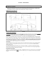
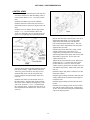
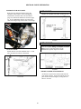
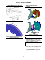
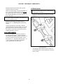
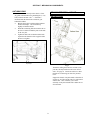
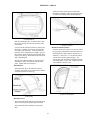
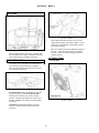
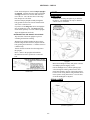
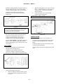
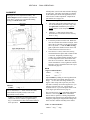
ASSEMBLY
AND
SERVICE MANUAL
FOR THE
E.R.A. 289FIA/USRRC
Chassis 2126 on
Revision 4b
March 2009
© Era Replica Automobiles 2009
1
SECTION A - PARTS NEEDED
PICKING UP YOUR KIT
The kit can be transported from our factory in an enclosed trailer, standard automobile trailer or rampback hauler.
Shipping space for the parts in cartons will also be required, although most will fit inside the kit. We have used
several shipping commercial companies with excellent results. See page 27 for names.
DIMENSIONS AND WEIGHTS
800 lb. bare + 200 lb. of boxes + 600 lb. for roller
a\shipdim
TRAILER REQUIREMENTS
If you didn't buy a "roller" from us, the kit is usually shipped on the dolly wheels that we use for assembly if your trailer
is well sprung. The dolly wheels require a $300 refundable deposit. Many people keep the wheels until their kit is
completed - it's very convenient for the kit to be mobile (and at the correct height) during construction.
The track of the Cobra dolly wheels is only about 20". Your trailer may require additional boards to support the dolly
wheels. Without tires or dolly wheels, you can put tires as buffer between the chassis and the trailer. The kit will have
to be lifted on and off the trailer manually. Have 3 strong friends to unload! If you’re coming on a weekend to pick up
your kit, please warn us if you aren’t coming with extra people too. Don’t tie down the dolly wheels to secure the kit.
Tie to the chassis or suspension. In the absence of suspension pieces to tie to, wrap soft tie straps around the front
crossmember and the upper mounting bolts for the rear subframe.
TIE-DOWNS
You or your shipping agent will require ratchet tie-downs, come-alongs and/or strong straps. We recommend either 4
diagonal connections or 2 longitudinal and 4 lateral ones for a total of 6. Don’t forget that the trailer must have
anchor points to tie to.
To avoid scratching the paint on the chassis, use 2" wide loops (or double 1" wide loops) or ratchet straps, 5000 lb.
minimum rating. Make sure that your trailer has places to tie to. If you use chains or a come-along, bring padding or
nylon straps for intermediate connections to the chassis.
INCLEMENT WEATHER:
A plastic cover will quickly shred at highway speeds. A high quality cloth car cover can be used to cover up the plastic,
but it must be held down with rope all over. Looseness will allow any cover to quickly beat itself (and your paint job)
to death.
7
SECTION A -PARTS NEEDED-
SHIFT LINKAGE
REAR DRIVE/SUSPENSION ASSEMBLY
The 289/FIA is designed to use either the Jaguar rear
suspension (in an E.R.A. subframe) or the custom
E.R.A. suspension unit with outboard brakes. The
E.R.A. unit is available as a kit or as a complete
assembly.
All shift linkage is available from E.R.A.
TOP LOADER
SHIFT LINKAGE
Both the original Ford 4-speed shift linkage and
Hurst linkage work well. The linkage is mounted at
the forward location on the transmission. Not all
top-loader tail shafts have the casting bosses for the
front mount but the tailshaft can be replaced. Some
may require drilling and tapping.
JAGUAR-BASED
SELECTION
See page 23 for application list.
The Jaguar differential is the same Salisbury unit that
was used in the original Cobra with only some casting
changes. It is adequate for 500+ BHP, and can be made
even stronger by using stub axle parts from Concours
West. Gear wear is not normally a problem even in wellused assemblies, but always replace seals.
fia\man\b\shiftmt
LEVER
If you don't want to modify the Mustang lever yourself
(see page 40), E.R.A. manufactures a duplicate the
original shift lever to fit the Top-Loader, Richmond
Gear and Tremec transmissions.
Do NOT replace the control arm roller and needle
bearings with aftermarket urethane bushings! The net
result will be wheel hop and generally sloppy handling.
RICHMOND GEAR
The vintage of the Jaguar differential is punched in the
casting at the lower right corner of the cover. The top
number indicates the year, the bottom number is a
special code. (Translation: we don't know what it's used
for). A simple way to determine whether a post-1980
unit will work is the presents of inboard brakes. The
later (inappropriate) assemblies have brakes mounted on
the hub carriers.
E.R.A. modifies a Long shifter and rods for the 5speed, using the Ford lever for control. The lockout
"T" handle is there for looks, but no longer is
functional. Inquire about available parts.
When selecting/buying a used rear end look for:
•
Completeness - You don't need the Jag trailing
arms or emergency brake compensator, but you
do need everything else.
•
Limited Slip Differential - Note that some XJ
differentials were open. A limited slip may be
retrofitted at the time of rebuild for about $700
•
Brakes - Try to get serviceable hydraulic and
emergency brakes. There were no major
changes in XKE rear brake until 1968 when
both the calipers and rotors were updated. The
later units are cheaper and easier to rebuild than
the early units.
15
SECTION B - PARTS PREPARATION
ALTERNATOR MOUNTING:
ENGINE COMPONENTS
Serpentine belt engines must change to the
following components:
Because of the likely variation of your components,
we obviously cannot give complete enging rebuilding
instructions here. What follows are the E.R.A.specific requirements for your engine. General
torque specifications for typical fasteners are found
on page 132. Good reference books for Ford engines
are listed on page 134.
1
980 lower pulley - modify by removing the outside
groove.
1980 upper pulley
1979 water pump
The alternator pivots in the outer mounting hole in
the head as shown below. Some aftermarket heads
require a threaded insert (Ford # F4ZZ-6E086-A) to
7
reduce threads to /16"USS. The adjusting bracket
between the alternator and the upper right water
pump bolt is included in the kit. If you use both
spacers, an external brace should be put between
the outside end of the alternator mounting bolt and
the water pump. Because there are so many
possible combinations of water pump, pulley and
heads, this brace is not included in the kit. Use a
straight-edge to figure what combination of spacers
(and possibly washers) will be required for all the
pulleys to line up.
BASIC PREPARATION
Remove cooling fan from engine water pump
pulley.
Install the fitting for the water temperature gage in
the intake manifold adjacent to the distributor..
Some Smiths temperature gages require a 1/2"NPT
hole. If space permits, you may adapt with a
Weatherhead fitting, 3200 x 8 x 6. Otherwise, drill
and tap the manifold to 1/2" NPT. You may remove
the heater fitting in the manifold too. Plug the hole.
If necessarey, install aa 1/2"NPT fitting in the oil
pan. Most Canton and Aviad pans already have
this fitting.
Install the engine mounts onto the block as shown
below.
fia\man\b\altbrk
fia\man\b\engmts
Install the long bolt through the (reinforcing
bracket), alternator and spacer tube.
Bolt the assembly onto the cylinder head.
Install the top adjusting bracket as shown.
Loosely secure the inner end of the reinforcing
strap to the water pump bolt as indicated.
Tighten the alternator pivot bolt.
Tighten the reinforcing strap bolt.
Check the alignment of the pulley grooves with a
straight-edge. Add washers or shorten the spacer as
needed.
29
SECTION B - PARTS PREPARATION
CLUTCH
Install the clutch pilot bearing,, driven disk and
pressure plate.
TRANSMISSION
ALL
Install the rear mount onto the transmission.
TREMEC
Stock series 600 transmissions have an input shaft
that requires a spacer between the transmission and
bellhousing. A transmission with a shortened input
shaft is available from various sources and obviates
the need for the spacer.
The Tremec TKO series have a boss on the right
side that must be trimmed back flush with the
adjascent rib. See at right. The passenger’s side
floor may also require some trimming where the
transmission comes close.
TKO 3550
The TKO 600 shifter can be moved forward from
the stock for better positioning:
TKO 500/600
Some Tremec transmissions require an aluminum
adapter between the transmission and the mount. In
addition many people prefer to use a concentric
throwout bearing with the Tremec. If you do,
McLeod (and ERA) recommends that you remove
any centrifigul weights from the clutch pressure
plate.
CLUTCH THROW-OUT FORK
We recommend that you use the fork listed on page
24 for all bellhousings. Call us for special
instructions for the T-5. See the bell housing notes
following.
30
SECTION B - PARTS PREPARATION
BELL-HOUSING
(PUSH TYPE)
See page 118 for hose installation and other details.
Notes:
The bell housing depth (face to face) for the T-5 is
about 6.8". If you are using a push-type release lever,
the pivot must be spaced about 5/8" forward.
The bracket and slave cylinder assembly is fastened
in three places:
•
The tapped hole on the left side of the block
bell-housing flange (where the original clutch
shaft pivot ball went).
•
The rear bolt of the left engine mount..
•
The left rear oil pan tapped hole.
The Tremec transmission also requires a deep bell
housing or a bell housing with a 5/8" spacer for the
input shaft not to interfere with the pilot bearing.
Many blow-shield type bell-housings have a large
bottom flange that will extend below the chassis.
Trim the engine plate as shown and use it as a
template to trim the bell-housing flange. This
dimension applies to all engines, although the
trimming operation may not be necessary for some.
Note! When the slave cylinder is installed in the
bracket, the bleeder must be at the top.
fia\man\b\clslave1
BLOWSHIELD MOUNT:
Use the appropriate holes to line up the slave
cylinder axis with the throwout fork.
CLUTCH THROWOUT ROD
b\belltrim
E.R.A. supplies two threaded rods with the pushtype slave cylinder to link with the throw-out fork
in the bell-housing. If your throw-out lever has a
hole in it, use the long threaded rod. If there is just
a socket, use the short rod. See page 119 for
assembly.
The optional E.R.A./Lakewood blow-shield from
ERA is already trimmed.
For other engines, trim the bell-housings similarly,
using the distance from the centerline of the
crankshaft to the bottom edge of the flange.
Install the correct link either by shortening the
adjustment or loosening the adapter bracket from
the block. A return spring is optional.
CLUTCH SLAVE CYLINDER
We recommend the following combinations (with
small block Ford) for easiest installation:
T-5, Tremec
Top-loader, Richmond
Gear 5 spd
CLUTCH SLAVE CYLINDER
Concentric throwout
bearing
(T-5 -PULL TYPE)
Inquire at ERA
External slave
cylinder
Details for using the concentric bearing are
available from ERA and on the internet. Inquire.
31
SECTION B - PARTS PREPARATION
SLAVE CYLINDER, INTERNAL
Some clutch/transmission combinations work best
with an internal (concentric) clutch slave cylinder.
This type of clutch release is self-adjusting, but
requires careful initial adjustment to compensate
for different clutch finger heights. It is very
sensitive to proper setup.
Install the bell housing. Using a straight-edge
across the bell housing opening, measure the height
of the fingers below the opening. Make sure that
the cylinder piston is pushed all the way into the
housing.
Adjust the height of the bearing on the transmission
by screwing the threaded adjusting sleeve in or out
of the slave cylinder so that when the transmission
is installed, there will be the indicated clearance.
We typically use Weber brand, and have found
them to be reliable if properly done. When you
assemble your car, it is essential to follow the
installation guidelines. Pictures and procedures
shown here are particular to Weber - yours may be
different. Always read and follow the instructions
for your installation.
After the transmission is installed permantly,
recheck the clearance and connect the pressure hose
to the clutch master cylinder.
Attach the bleed hose to the bellhousing flange at a
conveniently accessible location.
Weber brand cylinders (and most others) have no
system to keep the "piston" from being pushed too
far out of the cylinder - and puking fluid all over
the floor. The ERA requires a pedal stop so that the
master cylinder stroke is limited.
OIL PAN:
There are several aftermarket pans and OEM Ford
designs listed on page 22. If the pan does not have
a oil temperature bung, weld the oil temperature
adapter fitting (packed with the auxiliary
instrument pieces) onto the left side.
NOTE!
McLeod recommends that you remove any
centrifigul weights on the clutch pressure plate
when you use a concentric throwout bearing.
STARTER
Because Ford ringears have several offsets, the
starter must be matched correctly. Measure the
distance from the plane of the rear face of the
engine to the near edge of the ring gear teeth. “A”
varies from ¼” to 5/8”, so you might have to visit
your jobber for the correct unit.
ADJUSTMENTS
"Permantly" install all the clutch components onto
the flywheel, using an alignment tool for the driven
disc.
32
SECTION B - PARTS PREPARATION
Weber Manifold (two outlets)
Use a drilled freeze plug in the upper hose to
restrict flow.
fia\man\b\uwathose2
SMALL HOSES:
If you are not using a heater, connect the water
pump inlet to the expansion tank.
REAR SUSPENSION - JAGUAR
Right exit water pump
UPPER
4 bbl and single outlet Weber manifold
DISASSEMBLY
Components must be thoroughly checked and
rebuilt if necessary: brake calipers, emergency
brake pads and linkage, universal joints on halfshafts, hub carrier and lower control arm bearings.
Bearings, etc. are listed on page 129. We have
found that the Spicer® U-joints listed are the only
brand that meets the standards required of the
Jaguar half-shafts (and we've tried quite a few).
Replace any corroded or damaged brake lines. Be
sure to use lines with the proper end flare and
fittings. Note that some British fittings have a
convex (bubble) flare that mates with a concave
receptacle in the caliper. While this is similar to
some metric fittings, the threads are SAE. It is not
possible to make these flares with a conventional
flaring tool. Aftermarket suppliers and Jaguar
dealers have these British style lines.
Mount the brass junction block on the left front of
the cage, with the fitting for the flex hose up. If
your rear suspension core has the junction block
pointing forward, fabricate a small bracket from 1/8"
steel strap. Install the hose (mounted on the
chassis, originally) onto the junction with a copper
"0" ring.
Use a short neck thermostat housing (20° up) on the
intake manifold. Cut and trim the hose as shown:
34
SECTION B - PARTS PREPARATION
ASSEMBLY
Technique One
AXLE ASSEMBLY
Insert the hub with outer bearing into the hub
carrier.
The stock Jaguar XJ inner axle must be shortened to
XKE Series I/II length. Alternately, you may build
the axle from scratch. Specifications are available
from us. Complete assemblies and parts are available
from E.R.A.
Moderately press the outer bearing onto the small
end of the hub so that the bearing seats into the
bearing cup. Check that there is no axial play of
the hub, but it still rotates freely.
Measure the distance from the hub end to the
bearing surface with an accurate dial indicator.
Clean and deburr the axle splines.
Find the next size larger spacer in the chart.
Assemble the stub and inner axle together,
replacing the universal joints with genuine Spicer
units (5-160X).
Hub Carrier
Assemble the spacer onto the stub axle, install the
axle assembly into the hub, lining up the cotter pin
holes in each. Install a flat washer and nut.
Tighten the nut to 140 lb-ft.
Note that the lower pivot shaft is a shrink fit into
the aluminum casting. It may be removed by
heating the assembly or, less preferably, by using a
press. Generally, removal is not necessary.
Check the end-play with a dial indicator. If it is
correct, tighten the nut to the next near hole and
install the cotter pin.
Available shims:
Jag part #
CAC3818/10
Thickness
CAC3818/12
0.112"
CAC3818/14
0.114"
CAC3818/16
0.116"
CAC3818/18
0.118"
CAC3818/20
0.120"
CAC3818/22
0.122"
CAC3818/24
0.124"
CAC3818/26
0.126"
CAC3818/28
0.128"
CAC3818/30
0.130"
CAC3818/32
0.132"
Press the inner and outer bearing races and outer
seal only into the carrier.
CAC3818/34
0.134"
CAC3818/36
0.136"
Install the seal race and the outer bearing onto the
hub. Make sure that both are completely seated.
CAC3818/38
0.138"
d\rerahubx
Clean the hub carrier casting of any machining
debris, especially on the inside.
0.110"
Technique Two
Install the seal race onto the stub axle.
Hold the hub carrier vertically in a vise with the
inner end of the hub uppermost. Place the special
collar tool (Jag tool No. J15) on the hub end. Place
the inner bearing inner race on the hub and press
the race onto the hub until the inner face is flush
with the special collar. This will provide end flat
bearings. The end float should then be measured
with a dial test indicator. A spacer should then be
fitted in place of the Special collar to give end float
of .002"-006". Spacers are supplied in the
thicknesses shown below.
ADJUSTING HUB END FLOAT
When the hub carrier is assembled, the end float of
the axle/bearing assembly should be adjusted with
shims to between .002” preload and .004” float.
Aim for zero. You can change the end float with
the correct size of spacer from Jaguar, SICP,
Concours West, or E.R.A. See the list of available
shims below.
Pack the inner and outer bearings with good wheel
bearing grease. Also fill (about half-way) the
cavity in the hub carrier. Install the inner oil seal.
37
SECTION B - PARTS PREPARATION
For example, assume the end float measured to be
.025". Subtract the nominal end float of .004" from
the measured end float giving .021". Since the
Special Collar is .150" thick, the thickness of the
spacer to be fitted will be 0.150"- 0.021" i.e. .129".
The nearest spacer is 0.128" or 0.130". For
competition, use the spacer yielding more end float.
When the axle shaft has been fitted and nut
tightened (140 lb.ft.), check the end float with a dial
indicator. If it is correct, tighten the nut to the next
near hole and install the cotter pin.
Install both the seals into the hub carrier.
Re-assemble the hub carrier with hub and axle.
Turn the assembly upside-down. Install the bottom
section of the subframe by inserting the rear ears
just in front of the rear flanges of the top. Rotate
down in the front to match the front holes and
loosely attach the front with 5/16"USS x 3/4”L hex
cap screws and flat washers. Align the rear flanges
of the upper and lower sections with the 5/8" lower
5
radius arm bolts. Insert the /16"USS x 3/4" bolts (flat
washers on both sides) and secure with stover nuts.
Install the washer and retaining nut. Tighten the
nut to 225 lbft. Without an air wrench, you may
want to wait until the car is on the ground for final
torqueing.
Install the upper bracket onto each hub carrier and
torque the bolts to 75 lb-ft. Note the orientation
below for the left hub carrier. The right is the
mirror image.
Use Grade 5 torque specs on page 132 for all
fasteners
Loosely fasten the bottom of the subframe to the
differential using 1/2"USS x 11/4" bolts, flat and lock
washers. Shims may be necessary between the
channel and the casting, so don't tighten the bolts
yet.
Tighten (in sequence) the top differential bolts, the
bolts between the top and bottom subframe pieces.
If the clearance between the differential and the
bottom section of the subframe is greater than
.040”, insert shims to fill the gap. Use a medium
grade threadlocker on the bolts.
Install the bushings and side brackets on the front
mount tube. Tighten one castle nut to 5 lb-ft and
back off so that the slot aligns with the nearest hole
in the shaft. Tighten the second nut to 15 lb-ft and
back off to the nearest hole.
fia\man\d\erahubc
ASSEMBLY INTO SUBFRAME
Rebuild the differential as necessary. Some units
have a separate caliper mounting bridge on the side
bearing housing. This bracket and the original
Jaguar rotor can be left off.
Place the differential on the bench, right-side-up.
Allow the snout to extend over the edge of the
bench several inches. Raise the back up about 3/4"
with a block of wood, etc. Loop the front of the
subframe over the nose of the differential. Loosely
bolt the top of the subframe to the top of the
differential with (4) 1/2"USS x 11/4"L bolts, flat
washers and lock washers.
b\rsasblyf
38
SECTION B - PARTS PREPARATION
CONTROL ARMS
Install a male (right-hand-thread) rod end onto each
front lower radius arm so that the bushing center to
rod end center distance is 16". Leave the jam nuts
loose.
Install the steel brake lines onto the subframe.
Install the front lower radius arms onto the lower
differential bracket as shown, leaving the inner bolt
loose.
Install the coil-over damper onto the upper mount
using a 1/2" x 2 3/4"L bolt with flat washers and
stover nut. Install the coil-over onto the lower arm
(spacers, too), tightening the top and bottom bolts.
fia\man\d\hsaxlflg
Bolt the half-shaft inner ends and spacer onto each
differential output flange. If you wish, install
Jaguar shims with about .060" total thickness
between the half-shaft and the spacer. This will
make minor camber adjustments easier after basic
alignment has been done.
Slide the axle into the hub carrier, using a small
amount of light grease on the splines. For
competition, you might want to use a little shaftand-bearing mount on the splines, but be aware that
disassembly requires heat. Secure with a flat
washer and castle nut.
Tighten all the lower hub carrier pivot shaft nuts to
20 lbft, back off 1/3 of a turn to the nearest cotter
pin hole and insert cotter pin. Insert any shim
washers necessary between the rear flank of the rod
ends and the cage bracket. Install a flat washer and
lock nut.
fia\man\d\rsasblyt
Insert the thrust washers and inner bushings into the
hub carrier assembly. Lightly lubricate the inside
with heavy grease (silicone or moly base is best).
Install the hub carrier onto the front radius arm.
Loosely install the second bush half, washer and
castle nut.
Install the caliper using M10 x 30 allen screws and
ribbed lock washers.
Install the upper trailing arm bracket with bolts, flat
washers and lock nuts so that the bracket angles in
toward the front.
Install the rear radius arm onto the hub carrier in
the same manner. Slide the other (inside) end into
the bracket on the subframe and temporarily secure
with a bolt. Insert the 3/8"-16 x 5/8"L bolts through
the connecting plates. Tighten each castle nut to 15
lb-ft and back off to the nearest hole. Secure with a
cotter pin.
Install the upper trailing arms onto the hub carrier
bracket.
Install the lower trailing arm onto the lower radius
arm with flat washers and lock nut. Tighten nut to
35 lbft. The front of the trailing arm is attached the
same as the Jag suspension.
39
SECTION B - PARTS PREPARATION
EMERGENCY BRAKE CABLE
SHIFT HANDLE
Route the long cables through the hole in the
subframe as shown above. Pass it through the
internal holes, the holes above the front mount
(page 38), and into the balance bar shown on page
35. If you supplied the calipers, cut a slot in the
cable mount big enough for the cable to fit through.
Handles are available from E.R.A. and Finish Line
b\shiftlev
SHIFT LINKAGE
E.R.A. has complete linkage and adapters for Hurst
linkage for those who don't want to do the
modifications required. Inquire for details.
ANTI-SWAY BAR
5
Install onto the rear of the subframe with /16"-USS
nuts, flat and lock washers as illustrated.
b\shftlink
TREMEC 5 SPEED TRANSMISSIONS
All Tremecs except for the 500 and 600 retain the
stock shifter location. On the 500 and 600, the rear
plate can be turned 180 degrees, moving the lever
about 3” forward.
b\rerasbmt
40
SECTION F -MECHANICAL COMPONENTS-
12” BRAKES: HUB AND ROTOR MOUNTING
OPTIONAL WILWOOD CALIPER
MOUNTING
f/fjfz2.gif
Late Design with cutom uprights
GENERAL INSTALLATION
Note that the rotors are directional and must be
mounted on the correct side.
Replacement parts are listed on page 129.
Pin drive: If the rotor is not already installed on the
pin drive hub, torque the drive pins to 35 lb-ft
(with high-strength thread locking compound, i.e.
Locktite® red) and the nuts to 35 lb-ft.
If you ever need to remove the pins, they will have
to be heated to 300 deg. to weaken the bond.
Excessive heat will weaken the pins.
Always grind the rotor after installing the wheel
bearing races. If you don't have a special driver for
the races, let the auto machine shop install them.
Clean off the grinding dust thoroughly before
putting grease in the hub and installing the bearings
and inner seals.
Install the dust shields onto the steering knuckles if
desired.
69
SECTION F -MECHANICAL COMPONENTS-
Install the hub onto the stub axle with a special
(tanged) washer and castle nut.
STEERING GEAR
With new wheel bearings, torque the axle nut to 20
lb-ft. Loosen the nut and re-torque to 15 lb-inches,
then tighten to the nearest cotter pin hole. Install
the cotter pin through the access hole in the side of
the pin-drive hub.
The lower steering column must be installed before
the steering gear. See page 79.
Prepare the rack and pinion assembly as described
on page 41.
Note that the calipers and handed. Install them with
their bleeder nipple at the top.
Install the brake calipers and pads using new
hardware kits. Use silicone grease on all sliding
surfaces.
Connect the brake line to the caliper, using the
supplied banjo bolt and copper washer. If you still
get seepage past the copper washer but the seat is
not too bad, you may use a special sealing washer
available from Earls or E.R.A.
COIL-OVER DAMPER
See page 68. Spacers for the lower mounts are
provided with the dampers. Orient the damping
screw adjuster toward the centerline of the car. Use
a washer on either side of the top mount. Secure
the top with a 2 3/4" long bolt in from the back. A 2
l
/2" bolt is supplied for the bottom attachment.
Again, slide the bolt in from the back.
g\steeringgearmt
After putting a small amount of blue Loctite® (or
similar thread locker) on the bolt threads, torque the
bolts to 65 lbft.
70
SECTION F -MECHANICAL COMPONENTS-
ANTI-SWAY BAR
REAR SUSPENSION, JAGUAR
Threaded holes are already on the chassis. Chase
any paint in the threads before installing the (5/16-18)
15
bolts, washers and nuts. The /16" front bar is
mounted under the front frame extensions, just
behind the radiator.
•
Bolt the bar in place with the rubber/urethane
bushes and clamps. The ends slant up
slightly toward the outside.
•
Install the connecting links between the tab on
the lower control arm and the pads on the ends
of the sway bar.
•
Tighten the link bolts so that the rubber bush
expands to the diameter of the cupped washer.
Do not over-tighten.
INSTALLATION
d\fswayb
d\jagrs
Thread the trailing arms onto the rod-ends (with
jam nuts) already installed on the lower control
arms. See page 36. Thread on until two or three
threads are left showing, but leave the jam nuts
loose.
Support the chassis with jack-stands so that there is
at least 19”-20” between the spare tire well bottom
and the floor. This will allow you to fit the
assembly on the jack and still slide it under the car
from the back.
71
SECTION G - BODY II
Adjust the striker on the bracket so that when
latched the lid slightly compresses the gasket and
sits flush and centered on the surrounding body.
ebod\TRNKSEAL
Bolt the trunk hinges (they are marked with a T on
the lid side) loosely onto the body with any shims
found earlier.
fiat\man\e\trnkltch
Loosely bolt the trunk lid (with factory shims) onto
the hinges. Carefully close the lid, not letting the
front edge contact the body. Center the lid in the
opening. Slowly lift the lid just enough to get your
arm (and a wrench) inside and snug the bolts on the
lid part of the hinges. Remember to check the front
edge while lifting lid.
REAR CLOSING PANELS
Install the panels that seal the rear wheel area from
the passenger compartment with sealant and rivets.
Hold the panels in place with the original screws
9
and drill ( /64" holes) for 1/8" rivets into the chassis
vertical tubes and the bottom outrigger. The
closing panel with the bulb trim should contact the
outer body lightly. If you want, complete the seal
with urethane or silicone sealer.
The lid can be adjusted further by moving the lid
and hinges in unit at the connection on the inner
panel. Tighten bolts and recheck fit.
TRUNK STAY
Attach the trunk stay to the trunk lid as shown,
using the sheet metal screws at the bottom, stainless
steel dome head screws at the top.
fiat\man\e\RCLSPANL
ebod\trnkstay
TRUNK LATCH
Attach the trunk handle and latch to the trunk lid as
shown. Don't forget the gasket under the handle.
Attach the latch striker and bracket to the trunk
floor.
87
SECTION G - BODY II
ROLL BAR
fia\man\e\radmt
Fit the rubber grommets and steel sleeves to the
upper radiator support. Install the support over the
studs on top of the radiator with the large washers,
lockwashers and nuts.
Move the radiator forward and attach the support to
the body. Attach the support straps (or optional
rear fan, see below) between the upper and lower
radiator supports.
E\rollbar
When installing the bar (after paint), partially slide
the rear hoop into the chassis. About an inch before
fully seating the hoop, install the front brace.
OPTIONAL FANS
RADIATOR, FANS
STANDARD
The radiator can be installed from underneath the
car or from the top if the hood is not installed.
Insert the rubber radiator grommets into the holes
in the radiator support tray.
fiat\man\e\lradmt
From the bottom: Raise the radiator/fan unit and
tray up into place over the front chassis studs.
Hold in place with nuts, lock washers and flat
washers. Check that the radiator is centered in its
mounts. Gently let the radiator lean back against
the chassis.
fia\man\e\stdfan
From the top: Install the bottom tray onto the
chassis. Carefully slide the radiator down into
grommets.
88
SECTION G - BODY II
Install the grill lower pins into the holes and rotate
the top forward so that the top mount goes under
the top body lip. You will have to push the grill
down agains the rubber cushions to do this. Once
in place, adjust the tilt of the grill to the top
distance shown and drill two 1/8” or #30 holes for
the top #8 screws. Remove the tape and install
permanently.
GRILL
If ordered with the kit, the grill is already installed.
Retrofitting can be done as shown below:
Apply masking tape to the body lip along the inside
(rear) edges as shown. If the body is already
painted, use tape all around the inside of the
opening to prevent damage while fitting.
BUMPERS/JACK-PADS
The bumpers or jackpads are factory fit and
installed. The aluminum spacer sleeves can be
easily polished with very fine steel wool and/or car
polish.
Locate the lower holes by trial-fitting the grill in the
body hole. Insert the grill past the likely mounting
location and hold in the center of the body opening.
Mark the pin locations onto the lower pieces of tape
as a line projected directly forward. Check that the
center-to-center distance between the holes in the
body matches the pin spacing on the grill.
fiat\man\e\bumpers
INSTALLATION
Install the front and rear bumper mounts onto the
chassis. Front mounts should have locating marks
that were made when you disassembled the kit.
Leave the mounting bolts slightly loose.
Measure back from the front edge of the body
opening 1¾” and mark where that dimension
intersects with the pin line. Check again, because
that’s where you’re going to drill into the body.
Use a small pilot drill and then finish with a 7/32”
drill bit. Drill straight down first, and then tilt the
drill back about 20 degrees to make a tapered hole.
Typically, the holes will fall about ½” from the lip
edge.
Fit the rubber grommets to the body. Be sure the
lip is seated on both side of the fiberglass.
106
SECTION G - BODY II
Fit the studs and spacers onto the bumper uprights
or jackpads. Note that the upper spacers and studs
are longer than the lower ones on both front and
rear of the car. Leave the nuts loose if the nudge
bars (hoops) are to be fitted.
LIGHTS
HEADLIGHTS
All holes for mounting the lights are pre-drilled at
the factory. The headlights can only be installed
with the correct orientation.
Insert the bumper/jackpad assembly through the
body grommets and secure onto the frame/bracket
with a lock washer and nut.
If you have a rear nudge bar, the bar and uprights
must be installed as a unit. The front nudge bar
can be fitted separately or in unit with the uprights.
Align and tighten nuts and bolts.
RETROFITTING THE FRONT NUDGE BAR
Tape the sides of the front uprights to prevent
scratching and facilitate marking.
With the front uprights installed as shown above,
hold the nudge bar between them, aligned with the
body opening and with about 3/4" clearance between
it and the body.
Transfer the hole locations from the nudge bar to
the uprights.
Drill 3/8" holes in the uprights and install the
threaded inserts with a special tool or a nut and
bolt.
e\flights1
Mount the headlight assembly and gasket with four
#10 Phillips pan head tapping screws.
Pass the headlight wires (with the parking light
wires) through the rubber grommet in the inner
panel and rearward to the top of the spring perches.
Connect to the wiring harness and ground as shown
in the separate wiring instructions. Leave the rims
off till the headlights are adjusted.
ebod\rivnut
SIGNAL LIGHTS
fiat\man\e\fparkwir
107
SECTION G - BODY II
•
Install the parking light harness along the inside of
the inner panel, above the corner of the radiator,
securing it with the clamps on the top inner panel.
Connections are as shown in the following
illustration. Check the wiring instructions for
further notes.
•
With the parking lights on, the red wire should
be live. Touch the red wire to each pigtail (or
connector loop). Connect that wire to the
dimmest filament.
Connect the other wire to the remaining
receptacle at the bulb bottom.
LICENSE PLATE LIGHT
g\flights2
When making the wiring connections and inserting
the bulb, use a light electrical grease to prevent
corrosion from water and road salts.
Mount with the supplied #10 stainless nuts and
bolts. The lights have male and female terminals
which mate with the harness only one way.
Connect the black (ground) wire (with the eye
terminal) to one of the light mounting bolts.
ebod\liclite
INSTALLATION
Remove the attachment screw, lens and cover.
Insert the red wire through the larger of the 3 holes
in the deck lid and through the back of the light
gasket.
On some twist-off lights, it is possible to insert the
bulb two ways. If the the signal light is dimmer
than the parking light, remove the bulb, turn it 180°
and reinsert it
Connect the black wire to the case and the red wire
to the loop on the bulb holder.
TAIL-LIGHTS
Attach the light to the deck lid and refit the lens and
cover.
The lenses of the lights are mounted with the
lettering on the lens right side up.
Taillights may have pigtails with female
connectors. Otherwise connections are made
directly to the small receptacles on the light socket.
g\tailites
To make the tail light connections:
•
Make sure that the rear harness black ground
wire is connected to the light stud or ground
receptacle.
108
SECTION H
-FINAL OPERATIONS -
All ball joints, outer tie-rod ends and wheel bearings
are Chevrolet. The upper control arm pivot shaft is
an aftermarket part for the same application, but is
offset for more camber adjustment. Replacement
part numbers are on page 129.
ALIGNMENT
See pages 68-71 for suspension assembly. The
chassis height should be within the specifications
given above. Inquire for recommended starting
settings for all-out track work.
Caster
4 deg. +/- 1/2
•
The caster value of the left and right sides of
the car should differ by less than 1/2 deg., and
the right caster should always be equal or
greater than the left to compensate for road
crown.
•
Shifting a 1/8" shim from the front of the
bracket to the rear will decrease the caster by
about 1 1/4 deg.
Toe-in
1
/16"-1/8"
•
Loosen the jam nut on each tie rod. Rotate the
inner tie rod inside the rack boot to adjust. Each
turn of the tie rod relative to the end will change
3
the toe by about /16". With the ERA steering
gear, equalize the distance between the tie rod
center and the end of the inner sleeve.
•
Once the toe is correct, remove the steering
wheel/hub from the splines and re-install so that
is centered. Temporarily install the large
washer, wave washer and nut, torquing to 10 lbft. Final adjustment of the wheel can be done
after the car is test-driven. When the steering
wheel orientation is correct, tighten the column
hub nut to 25 lb-ft. Install the hub center cap as
described on page 101.
REAR
Jaguar w/inboard brakes
-3/4 deg. +/- 1/4
Toe-in
0.0" +/- /16"
1
Adjust Camber by adding or removing shims from
between the brake rotor and the inner drive-axle
flange. A 0.02” shim will change camber by ¼
degrees. Most setups will require only one shim,
less than is normally used in the original car so you
will have extra ones left over. New shims are
available from us or your local Jaguar dealer or one
of the Jaguar specialists listed on page 26.
h\camber
FRONT:
Camber
Camber
0 deg. +/- 1/4
We’ve included (12) 1/8” shims with the kit which,
when distributed equally usually results in the
approximate correct camber.
The rear wheel toe-in is not individually adjustable.
If the toe is out of range, the lower control arms
must be bent or replaced. Tracking (longitudinal
alignment of the front and rear suspensions) may be
changed by adjusting the length of the trailing arms
at the rod end to shift the assembly in the chassis.
Adding a 1/8" shim between each bracket and the
chassis will increase camber by approximately 1/2
deg. Use standard 1975 Chevrolet Camaro shims or
their equivalent.
E.R.A. w/ outboard brakes
Camber: -3/4 deg. +/- 1/4 deg.
122