1
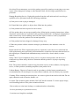
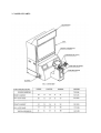
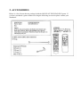
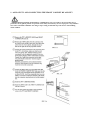
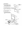
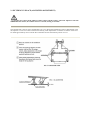
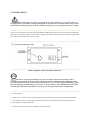
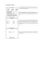
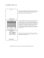
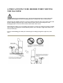
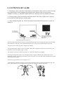
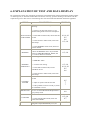
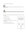
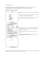
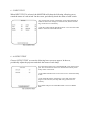
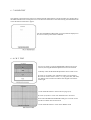
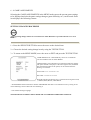
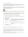
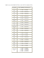
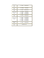
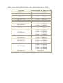
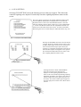
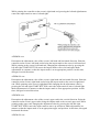
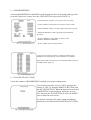
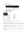
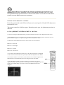
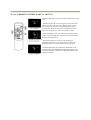
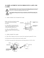
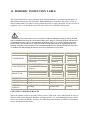
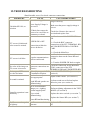
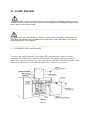
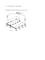
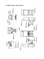
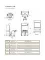
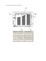
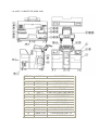
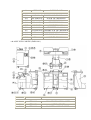
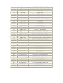
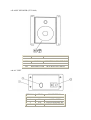
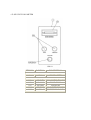
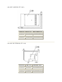
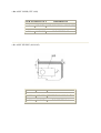
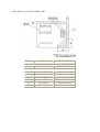
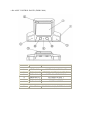
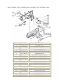
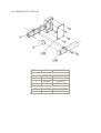
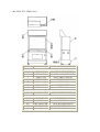
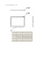
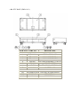
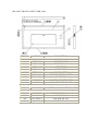
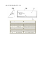
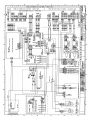
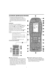
Deluxe Version
Operators’s Manual
HOUSE OF THE DEAD DELUXE TABLE OF CONTENTS
INTRODUCTION OF THE OWNERS MANUAL
GENERAL PRECAUTIONS
1. NAME OF PARTS
2. ACCESSORIES
3. ASSEMBLING PRECAUTIONS
4. PRECAUTIONS TO BE HEEDED WHEN
MOVING THE MACHINE
5. CONTENTS OF GAME
6. EXPLANATION OF TEST AND DATA DISPLAY
6-1 SWITCH UNIT AND COIN METER
6-2 TEST MODE
6-3 MEMORY TEST
6-4 T.G.P. TEST
6-5 INPUT TEST
6-6 OUTPUT TEST
6-7 SOUND TEST
6-8 C.R.T. TEST
6-9 GAME ASSIGNMENTS
6-10 COIN ASIGNMENTS
6-11 GUN SETING
6-12 BOOKKEEPING
6-13 BACKUP DATA CLEAR
7. CONTROLLER (GUN)
7-1 REPLACING THE MICRO SWITCH
7-2 REPLACING THE SENSOR BOARD
8. COIN SELECTOR
9. PROJECTOR
9-1 CLEANING THE SCREEN
9-2 MITSUBISHI MONITOR
10. REPLACEMENT OF FLUORESCENT LAMP
AND LAMPS
10-1 REPLACEMENT OF FLUORESCENT
LAMP
10-2 REPLACEMENT OF LAMPS
11. PERIODIC INSPECTION TABLE
12. TROUBLESHOOTING
13. GAME BOARD
13-1 EXPOSING THE GAME BOARD
13-2 COMPOSITION OF THE GAME BOARD
14. DESIGN RELATED PARTS
15. PARTS LIST
TOP ASSY ZMB DX
ASSY SHIELD CASE DX
ASSY CABINET DX
ASSY SUB-CABINET DX
ASSY SPEAKER
AC UNIT
SW UNIT/COIN METER
ASSY AMP BD
ASSY BUFFER BD
ASSY I/O BD
ASSY SW REGU
ASSY AC SUPPLY
ASSY CONTROL PANEL
CONTROL UNIT 1P/2P
SENSOR UNIT
ASSY PTV
ASSY MASK
PTV BASE
ASSY FRONT PANEL
ASSY BILLBOARD
16. WIRING DIAGRAM
SPECIFICATIONS
Installation space: 67 in.(L) x 47 in.(W)
Height: 89 in.
Weight: Approx. 663 lbs.
Power maximum current: 5 Amp AC 120V 60 Hz AREA
MONITOR: 50 INCH PROJECTION DISPLAY
SEGA ENTERPRISES, LTD., has for more than 30 years been supplying various innovative
and popular amusement products to the world market. This Owners Manual is intended to
provide detailed descriptions together with all the necessary installation, game settings and
parts ordering information related to the HOUSE OF THE DEAD dlx, a new SEGA product.
This manual is intended for those who have knowledge of electricity and technical expertise,
especially in ICs, CRTs, microprocessors, and circuit boards. Read this manual carefully to
acquire sufficient knowledge before working on the machine. Should there be a malfunction,
non-technical personnel should under no circumstances touch the interior system. Should the
need arise, contact our main office, or the closest branch office listed below.
SEGA ENTERPRISES, INC. (USA)
Customer Service
45133 Industrial Drive
Fremont, CA 94538
Phone 415-802-1750
Fax 415-802-1754
7:30 am - 4:00 pm, Pacific Standard Time
Monday thru Friday
INTRODUCTION OF THE OWNERS MANUAL
General Precautions
Follow Instructions: All operating and use instructions should be followed.
Attachments: Do not use attachments not recommended by the product manufacturer as they
may cause hazards.
Accessories: Do not place this product on an unstable cart, stand, tripod, bracket, or table. The
product may fall, causing serious injury to a child or adult, and serious damage to the product.
Use only with a cart, stand, tripod, bracket, or table recommended by the manufacturer, or
sold with the product. Any mounting of the product should follow the manufacturer's
instructions, and should use only mounting accessories recommended by the manufacturer.
Moving the Product: This product should be moved with care. Quick stops, excessive force,
and uneven surfaces may cause the product to overturn.
Ventilation: Slots and openings in the cabinet are provided for ventilation, to ensure reliable
operation of the product and to protect it from overheating; these openings must not be
blocked or covered. The openings should never be blocked by placing the product in a built-in
installation such as a bookcase or rack unless proper ventilation is provided or the
manufacturer's instructions have been adhered to.
Power Sources: This product should be operated only from the type of power source indicated
on the marking label. If you are not sure of the type of power supply to your location, consult
your local power company. For products intended to operate from battery power or other
sources, refer to the operating instructions.
Grounding or Polarization: This product is equipped with a three-wire grounding-type plug, a
plug having a third (grounding) pin. This plug will only fit into a grounding-type power
outlet. This is a safety feature. If you are unable to insert the plug into the outlet, contact your
electrician to replace your obsolete outlet. Do not defeat the safety purpose of the groundingtype plug.
Power Cord Protection: Power-supply cords should be routed so that they are not likely to be
walked on or pinched by items placed upon or against them, paying particular attention to
cords at plugs, convenience receptacles, and the point where they exit from the product.
Overloading: Do not overload wall outlets, extension cords, or integral convenience
receptacles as this can result in a risk of fire or electric shock.
Object and Liquid Entry: Never push objects of any kind into this product through openings
as they may touch dangerous voltage points or short-out parts that could result in a fire or
electric shock. Never spill liquid of any kind on the product.
Servicing: Do not attempt to service this product yourself as opening or removing covers may
expose you to dangerous voltage or other hazards. Refer all servicing to qualified service
personnel.
Damage Requiring Service: Unplug this product from the wall outlet and refer servicing to
qualified service personnel under the following conditions:
a) If the power cord or plug is damaged;
b) If liquid has been spilled, or objects have fallen into the product;
c) If the product has been exposed to rain or water;
d) If the product does not operate normally when following the operating instructions. Adjust
only those controls that are explained in the operating instructions. An improper adjustment of
other controls may result in damage and will often require extensive work by a qualified
technician to restore the product to its normal operation;
e) If the product has been dropped or damaged in any way;
f) When the product exhibits a distinct change in performance; this indicates a need for
service.
Replacement Parts: When replacement parts are required, be sure the service technician has
used replacements parts specified by the manufacturer or that have the same characteristics as
the original part. Unauthorized substitutions may result in fire, electric shock, or other
hazards.
Safety Check: Upon completion of any service or repairs to this product, ask the service
technician to perform safety checks to determine that the product is in proper operating
condition.
Heat: The product should be situated away from heat sources such as radiators, heat registers,
stoves, or other products (including amplifiers) that produce heat.
Lithium Battery- Dispose of batteries only in accordance with the battery manufacturer's
recommendations. Do not dispose in an open flame condition, since the battery may explode.
Cleaning: When cleaning the monitor glass, use water or glass cleaner and a soft cloth. Do not
apply chemicals such as benzine, thinner, etc.
Location: This an indoor game machine, DO NOT install it outside. To ensure proper usage,
avoid installing indoors in the places mentioned below:
· Places subject to rain/water leakage, or condensation due to humidity;
· In close proximity to a potential wet area;
· Locations receiving direct sunlight;
· Places close to heating units or hot air;
·In the vicinity of highly inflammable/volatile chemicals or hazardous matter;
· On sloped surfaces;
· In the vicinity of emergency response facilities such as fire exits and fire extinguishers;
· Places subject to any type of violent impact;
· Dusty places.
Installation Precautions
· Verify the amperage of the branch circuit outlet before plugging in the power plug. Do not
overload the circuit.
· Avoid using an extension cord. If one is required, use an extension cord of type SJT, 16/3
AWG rated min. 120 VAC, 7A.
· Moving this unit requires a minimum clearance (of doors, etc.) of 32" (W) by 77" (H).
· For the operation of this machine, secure a minimum area of 32" (W) by 42"(D).
Regulatory Approvals
This game has been tested and found to comply with the Federal Communications
Commission Rules.
This device complies with Part 15 of the FCC Rules. Operation is subject to the following two
conditions: (1) This device may not cause harmful interference, and (2) this device must
accept any interference received, including interference that may cause undesired operation.
This game has been tested and listed by Underwriters Laboratories, Inc., to ANSI/UL22.
3. NAME OF PARTS
2. ACCESSORIES
Below is a list of items that are packaged with the HOUSE OF THE DEAD DLX game. If
you have purchased a game without receiving the following accessories please contact your
distributer.
3. ASSEMBLING PRECAUTIONS
Assembling should be performed as per this manual. Since this is a complex machine, erroneous
assembling may cause damage to the machine, or malfunctioning to occur. When assembling, be sure to
perform work by plural persons. Depending on the assembly work, there are some cases in which
performing the work by a single person can cause personal injury or parts damage.
Note that the tools such as a Phillips screwdriver and wrench for M16 hexagon bolt w/24 mm
width across flats are required for the assembly work.
When carrying out the assembly work, follow the procedure in the following 5-item
sequence:
1. ASSY OF PTV AND CONNECTING THE FRONT CABINET DX AND PTV
When performing 8 and 9 below, it is difficult to carry out work by one person. Be sure to
perform work by plural persons. To perform work safely and securely, be sure to prepare a step which is
in a secure and stable condition. Not using a step or using an unstable step can cause a violent falling
down accident.
2. SECURING IN PLACE (ADJUSTER ADJUSTMENT)
Be sure to have all the Adjusters make contact with the surface. Unless the Adjusters come into
contact with the surface, the Cabinet can move of itself, causing an accident.
This machine has 4 each of casters and adjusters (fig. 3.2a). When the installation position is determined, cause
the adjusters to come into contact with the floor directly, make adjustments in a manner so that the casters will
be raised approximately 5mm. from the floor and make sure that the machine position is level.
3. POWER SUPPLY
Ensure that the power cord is not exposed on the surface (passage, etc.). If exposed, they can
be caught and are susceptible to damage. If damaged, the cord can cause an electric shock or short circuit.
Ensure that the wiring position is not in the customer's passage way or the wiring has protective covering.
The AC Unit is mounted on the left side of the FRONT CABINET DX. The AC Unit incorporates the Main SW,
Earth Terminal and Inlet. Firmly insert the Power Plug into the Socket Outlet and the other side of the plug to the
Inlet. Turn the Main SW ON to turn power ON.
REPLACEMENT AND ADJUSTMENT OF FUSE
In order to prevent electrical shock, be sure to turn power off before performing work by
touching the interior parts of the the product. Be careful so as not to damage wirings. Damaged wirings
can cause an electrical shock or short circuit accident. Be sure to use fuses meeting specified rating. Using
fuses exceeding the specified rating can cause a fire or electrical shock. After eliminating the cause of the
fuse blowing, continued use with the fuse as is blown can cause generation of heat resulting in fire.
1.> Unplug the unit.
2.> Remove the AC Switch Panel on the left side of the game which secures the PTV and Front Cabinet DX.
3.> The 3 fuses are now visible. Replace the blown fuse. Always replace the fuses with the same type and
current rating for continued protection.
4.> By using the reverse procedure reinstall the AC Switch Panel.
4. ASSEMBLY CHECK
In the TEST MODE, ensure that the assembly has been made
correctly and IC BD is satisfactory (refer to Section 6). In the test
mode, perform the following test:
Selecting the MEMORY TEST on the test mode menu screen
causes the on-board memory to be tested automatically. The game
board is satisfactory if the display beside each IC No. shows
GOOD.
Selecting the INPUT TEST on the test mode menu screen causes
the screen (on which each switch is tested) to be displayed. Press
each switch. For the coin switch test, insert a coin from the coin
inlet with the coin chute door being open. If the display beside
each switch indicates "ON," the switch and wiring connections are
satisfactory.
Select "OUTPUT TEST" from the Test Menu in the Test Mode to
have the Lamp Test Screen displayed. Check if each lamp lights
up satisfactorily.
4. ASSEMBLY CHECK cont'd
In the Test Mode, selecting SOUND TEST causes the screen, on
which the sound related BD and wiring connections are tested, to be
displayed. Be sure to check if the sound is emitted from each
speaker and the sound volume is appropriate.
In the TEST MODE menu, selecting C.R.T. TEST allows the screen
(on which the monitor is tested) to be displayed. Although the
monitor adjustments have been made at the time of shipment from
the factory, color deviation, etc., may occur due to the effect caused
by geomagnitism, the location building's steel frames and other
game machines in the periphery. By watching the test mode screen,
make adjustment as to whether an adjustment is needed. If it is
necessary, adjust the monitor by referring to Section 9. In case of
color deviation due to the monitor's magnetization, use DAMAGE
SW (see Section 6).
On the menu screen in the test mode, selecting GUN SETTING
displays the screen on which gun setting is set. Check to see if there
is any problem for playing game.
Perform the above inspection also at the time of monthly inspection.
4. PRECAUTIONS TO BE HEEDED WHEN MOVING
THE MACHINE
When moving the machine, be sure to pull out the plug from the power supply. Moving the
machine with the plug as is inserted can damage the power cord and cause a fire or electric shock.
When moving the machine on the floor, retract the Adjusters and ensure that Casters make contact with
the floor. During transportation, pay careful attention so that Casters do not tread power cords.
Damaging the power cords can cause an electric shock and/or short circuit.
When lifting the cabinet, be sure to hold the catch portions or bottom part. Lifting the cabinet by holding
other portions can damage parts and installation portions, due to the empty weight of the cabinet, and
cause personal injury.
Use care when handling glass made parts. When the glass is damaged, fragments of glass may cause
injury.
5. CONTENTS OF GAME
1.> Inserting a coin(s) causes the credit display on the bottom of the screen to count. Inserting
one credit worth of coin(s) changes the message on the bottom of the screen from the
"INSERT COIN(S)" to "PRESS START BUTTON" and both of the start buttons will flash.
2.> Pressing either of the start buttons determines which side (left or right) you are playing
on. Press the START button to start the game.
3.> After starting the game, the Title of the Stage being started and the purpose of game are
displayed.
· The life points and the number of bullets of the left-hand side player (1P) are displayed on the lower left-hand
side of the screen, and those of the right-hand side player (2P), on the lower right-hand side of the screen.
· The player loses one life if he shoots a hostage by mistake.
· The gun holds bullets. When it runs out of ammo, "RELOAD" is displayed on the screen. At this time, point
outside the screen and pull the trigger to reload.
· The enemy's axes, knives, drum cans, barrels, etc., can be shot down for your defense.
· Shooting the background scenery can cause Special Items to appear sometimes. The Special Items can be
captured by shooting. Capturing an item allows you to earn points or recovers life points (explanations as regards
to the Items are given later).
· When the life point becomes zero, the game is over.
· Downing the boss character awaiting you at the end of each stage results in clearing that particular stage. The
player cannot defeat the boss until his life meter becomes zero (the boss character's life meter)
4.> If you would like to join in the game at anytime while the other person is playing, insert a
coin(s) and press the start button. Also, when credits allowing the game to be played still
remain, the start button on the other side will keep flashing. The player can participate i the
game by pressing the flashing button.
5.> When the life point becomes zero, if you want continue, insert a coin(s) required to
continue and press the start button. If credits allowing the player to continue still remain, you
can continue by merely pressing the start button.
6.> At the time of game over, if the player's score ranks 10th or higher, hi/her name can be
entered.
CONCERNING SPECIAL ITEMS
LIFE> The life point increases by one. The upper limit of Life Point
can be set to 3, 4, and 5.
COIN or GOLDEN FROG> Capturing either of these items
increases the Life Point.
KNACK OF PLAY
·Accurately shoot at the head: In each stage, the head is the weak point of
enemy characters other than the Boss. Hitting the head greatly decreases the
enemy's life points and can down the enemy quickly. In the latter half of the
stages, the higher the stage level you proceed to, the more important the
shooting accuracy becomes.
·Look for your favorite routes: The stage has various routes which are
determined by the player's action. Some routes have less enemy appearance,
frequent life recovery, etc. You can master a knack of play by looking for
your favorite routes.
·Memorizing the enemy's appearance position: Since the enemy's appearance pattern is the same every time,
you can also master a knack of play by memorizing such pattern through repeated game play.
6. EXPLANATION OF TEST AND DATA DISPLAY
By operating the switch unit, periodically perform the tests and data check. When installing the machine intially
or collecting cash, or when the machine does not function correctly, perform checking in accordance with the
explanations given in this section. The following show tests and modes that should be utilized as applicable.
ITEMS
DESCRIPTION
SECTIONS
When the machine is installed, perform the
following:
1.> Check to see that each setting is as per
standard setting made at the time of shipment.
INSTALLATION 2.> In the INPUT TEST mode, check each SW
OF MACHINE and VR.
3.> In the OUTPUT TEST mode, check each
of the lamps.
MEMORY
4.> In the MEMORY TEST mode, check IC's
on the IC Board.
Choose MEMORY TEST in the MENU mode
to allow the MEMORY test to be performed.
In this test, PROGRAM RAMs, ROMs, and
ICs on the IC Board are checked.
Periodically perform the following:
6-9, 6-10
6-5
6-6
6-3, 6-4
6-3, 6-4
1.> MEMORY TEST
PERIODIC
SERVICING
2.> Ascertain each setting.
3.> In the INPUT TEST mode, test the
CONTROL device.
6-3, 6-4
6-9, 6-10
6-5
6-6
4.> In the OUTPUT TEST mode, check each
of the lamps.
1.>In the INPUT TEST mode, check each SW
and VR.
CONTROL
SYSTEM
PROJECTOR
IC BOARD
2.> Adjust or replace each SW and VR.
3.> If the problem can not be solved yet, check
the CONTROL's moves.
In the PROJECTOR ADJUSTMENT mode,
check to see if the PROJECTOR adjustment is
appropriately made.
1.> MEMORY TEST
2.> In the SOUND TEST mode, check the
sound related ROM's.
Check such data as game play time and
DATA CHECK
histogram to adjust the difficulty level, etc.
6-5
7
7
6-8
6-3, 6-4
6-7
6-12
6 - 1 SWITCH UNIT AND COIN METER
Never touch places other than those specified. Touching places not specified can cause electric
shock and short circuit.
Adjust to the optimum sound volume by considering the environmental requirements of the
installation location. If the COIN METER and the game board are electrically disconnected, game play is
not possible.
Open COIN CHUTE DOOR, and the switch unit shown appears. The function of each switch
is as follows:
1.> SOUND VOLUME
Controls the speaker volume.
2.> TEST BUTTON (TEST SW)
For the handling of the TEST BUTTON, refer to the section
on the test mode.
3.> SERVICE BUTTON (SERVICE SW)
Give credits without registering on the coin meter.
6 - 2 TEST MODE
This mainly checks if the operation of Game BD is accurate, and allows for COIN
ASSIGNMENTS/GAME ASSIGNMENTS setting Projector adjustments.
SELECTION OF TEST ITEMS
1.> Push the TEST BUTTON to cause the following TEST MENU
to appear.
2.> By pushing the SERVICE BUTTON, bring the arrow mark to
the desired item and press the TEST BUTTON.
3.> After the test is complete, move the arrow mark to "EXIT" and
press the TEST BUTTON to return to game mode.
The MEMORY TEST mode is for checking the on-BD memory IC
functioning. "GOOD" is displayed for normal ICs and "BAD" is
dispalyed for abnormal ICs.
° When the test is completed, if the display as shown left, it is
satisfactory.
° After finishing the test, pressing the TEST BUTTON allows the
MENU MODE to return on the screen.
In this test, T.G.P. (on screen display related IC) is checked. As shown at the left, if "GOOD" is displayed for all,
it is satisfactory. Press TEST BUTTON to return to the menu screen.
6 - 5 INPUT TEST
When INPUT TEST is selected, the MONITOR will show the following, allowing you to
watch the status of each switch. On the screen, periodically check the status of each switch.
1.> By pressing each switch, if the display on the right-hand side of
the name of each switch changes to ON from OFF, the SW and the
wiring connections are satisfactory.
2.> Open the COIN CHUTE DOOR and insert a coin from the COIN
ENTRY to check the COIN CHUTE SW.
6 - 6 OUTPUT TEST
Choose OUTPUT TEST to cause the following lower screen to appear. In the test,
periodically adjust the projector and check the status of each lamp.
Choose OUTPUT TEST to have the MONITOR screen shown left to
appear. This screen allows status to be checked. Periodically check
the lamp status in this mode.
Press the SERVICE BUTTON to move the arrow to the desired lamp
test item.
Press the TEST BUTTON. If the dispay to the right of the lamp
changes to ON from OFF, the lamp and wiring connection are
satisfactory.
Choose EXIT and press the TEST BUTTON to return to MENU
MODE.
6 - 7 SOUND TEST
This enables sound used in the game to be chacked. Sound related memory and each speaker are checked. Press
the SERVICE BUTTON to bring the arrow to the desired sound item to be tested. Pressing the TEST BUTTON
causes the desired sound test to appear.
Each time the SERVICE BUTTON is pressed, numeral displayed on
the screen counts up and sound is emmitted.
6 - 8 C.R.T. TEST
Select C.R.T. TEST to cause the MONITOR to display the screen
shown left, allowing MONITOR adjustment staus to be checked.
Periodically check the MONITOR adjustment status on this screen.
The screen (1/2) enables color adjustment check to be performed.
THe color bar of each of the 4 colors, i.e., red, green, blue, and white,
is the darkest at the extreme left and becomes brighter towards the
extreme right.
Press the TEST BUTTON to shift to the next page (2/2).
The screen (2/2) allows screen size and distortion to be tested.
Check if the CROSSHATCH FRAME LINE goes out of the screen
and if the crosshatch lines are distorted.
Press the TEST BUTTON to return to the MENU mode.
6 - 9 GAME ASSIGNMENTS
Selecting the GAME ASSIGNMENTS in the MENU mode causes the present game settings
to be displayed and also the game settings changes (game difficulty, etc.) can be made. Each
item displays the following content.
SETTING CHANGE PROCEDURE
Setting changes cannot be stored unless the TEST BUTTON is pressed while the arrow is on
EXIT.
1.> Press the SERVICE BUTTON to move the arrow to the desired item.
2.> Choose the desired setting change item by using the TEST BUTTON.
3.> To return to the MENU MODE, move the arrow to EXIT and press the TEST BUTTON.
· GAME DIFFICULTY: Game difficulty can be set in 5 different
levels from VERY EASY to VERY HARD.
· LIFE SETTING: The combination set of INTIAL LIFE (the number
of life points alloted to the player at the time of game start) and MAX
LIFE (the limited number of life points) can be selected from the
following 12 variations.
INTIAL LIFE: 1 2 3 1 2 3 4 1 2 3 4 5
MAX LIFE: 3 3 3 4 4 4 4 5 5 5 5 5
· BLOOD COLOR: The blood color is chosen from among the 4 kinds,
i.e., GREEN, RED, BLUE, and PURPLE.
· ADVERTISE SOUND: Determines whether ADVERTISE SOUND is to be emmited or not by setting to ON
when emmitting it and to OFF when not emmitting it.
· COUNTRY: Message language.
THE FOLLWING FIGURES/TABLES SHOW THE FACTORY RECOMMENDED SETTINGS.
6 - 10 COIN ASSIGNMENTS
Selecting the COIN ASSIGNMENTS in the MENU mode permits you to set the start number
of credits, as well as the basic numbers of coins and credits., This mode exptresses "how
many coins correspond to how many credits."
SETTING CHANGE PROCEDURE
Setting changes cannot be stored unless the TEST BUTTON is pressed while the arrow is opn
EXIT.
1.> Press the SERVICE BUTTON to move the arrow to the desired item.
2.> Choose the desired setting change item by using the TEST BUTTON.
3.> To return to the MENU MODE, move the arrow to EXIT and press the TEST BUTTON.
· COIN CHUTE TYPE: Sets the combination of the number of COIN
CHUTEs and the numbe of players as applicable. In the case that the
COIN CHUTE is changed, be sure the setting is made in a manner
meeting the replaced coin chute.
· COMMON: Coins are accepted in common for both players.
· INDIVIDUAL: Each player uses a coin chute which accepts coins
independently.
· CREDIT TO START: Number of credits requirede for starting game. (1~5 credits are selected.)
· CREDIT TO CONTINUE: Number of credits required for continuing game (1~5 credits are selelcted)
· COIN/CREDIT SETTING: Sets the CREDITS increase increment per coin insertion. There are 27 settings
from #1 to #27, expressed in XX CREDIT as against XX COINS inserted. (TABLE 6.10a, 6.10b) #27 refers to
FREE PLAY. When the COIN CHUTE TYPE is set to INDIVIDUAL, there are some setting numbers not
displayed as indicated in TABLE 6.10b.
· MANUAL SETTING: This allows credit increase setting as against coin insertion to be further set in the
manner finer than COIN/CREDIT SETTING (refer to TABLE 6.10c).
TABLE 6.10a COIN/CREDIT SETTING (COIN CHUTE COMMON TYPE)
SETTING
SETTING
#1
SETTING
#2
SETTING
#3
SETTING
#4
SETTING
#5
SETTING
#6
SETTING
#7
SETTING
#8
SETTING
#9
SETTING
#10
SETTING
#11
SETTING
#12
SETTING
#13
SETTING
#14
SETTING
#15
SETTING
#16
SETTING
#17
SETTING
#18
SETTING
#19
FUNCTIONING OF CHUTE #1
1 COIN ~ 1 CREDIT
1 COIN ~ 2 CREDITS
1 COIN ~ 3 CREDITS
1 COIN ~ 4 CREDITS
1 COIN ~ 5 CREDITS
1 COIN ~ 2 CREDITS
1 COIN ~ 5 CREDITS
1 COIN ~ 3 CREDITS
1 COIN ~ 4 CREDITS
1 COIN ~ 5 CREDITS
1 COIN ~ 6 CREDITS
1 COIN ~ 1 CREDIT
1 COIN ~ 1 CREDIT
1 COIN ~ 2 CREDITS
1 COIN ~ 1 CREDIT
2 COINS ~ 3 CREDITS
1 COIN ~ 3 CREDITS
1 COIN ~ 1 CREDIT
1 COIN ~ 1 CREDIT
1 COIN ~ 1 CREDIT
2 COINS ~ 2 CREDITS
3 COINS ~ 3 CREDITS
4 COINS ~ 4 CREDITS
SETTING
#20
SETTING
#21
SETTING
#22
1 COIN ~ 5 CREDITS
5 COINS ~ 1 CREDIT
1 COIN ~ 2 CREDITS
SETTING
#23
2 COINS ~ 1 CREDIT
4 COINS ~ 2 CREDITS
5 COINS ~ 3 CREDITS
SETTING
#24
1 COIN ~ 3 CREDITS
SETTING
#25
1 COIN ~ 1 CREDIT
2 COINS ~ 2 CREDITS
3 COINS ~ 3 CREDITS
4 COINS ~ 4 CREDITS
5 COINS ~ 6 CREDITS
SETTING
#26
SETTING
#27
1 COIN ~ 6 CREDITS
FREE PLAY
TABLE 6.10b COIN/CREDIT SETTING (COIN CHUTE INDIVIDUAL TYPE)
SETTING
SETTING #1
SETTING #6
SETTING #8
SETTING #9
SETTING #10
SETTING #11
SETTING #12
SETTING #15
SETTING #17
SETTING #18
SETTING #19
SETTING #21
SETTING #22
SETTING #23
SETTING #25
SETTING #27
FUNCTIONING OF COIN CHUTE
1 COIN ~ 1 CREDIT
1 COIN ~ 2 CREDITS
1 COIN ~ 3 CREDITS
1 COIN ~ 4 CREDITS
1 COIN ~ 5 CREDITS
1 COIN ~ 6 CREDITS
1 COIN ~ 1 CREDIT
1 COIN ~ 1 CREDIT
2 COINS ~ 3 CREDITS
1 COIN ~ 1 CREDIT
1 COIN ~ 1 CREDIT
1 COIN ~ 1 CREDIT
2 COINS ~ 2 CREDITS
3 COINS ~ 3 CREDITS
4 COINS ~ 4 CREDITS
5 COINS ~ 1 CREDIT
1 COIN ~ 2 CREDITS
2 COINS ~ 1 CREDIT
4 COINS ~ 2 CREDITS
5 COINS ~ 3 CREDITS
1 COIN ~ 1 CREDIT
2 COINS ~ 2 CREDITS
3 COINS ~ 3 CREDITS
4 COINS ~ 4 CREDITS
5 COINS ~ 6 CREDITS
FREE PLAY
6 - 11 GUN SETTING
Selecting GUN SETTING causes the folowing screen at the top to appear. This allows the
controller sighting to be adjusted. Periodically check the sighting adjustment status on this
screen.
The screen shown at the left is the sighting adjustment menu mode.
Press the SERVICE BUTTON to bring the arrow to the desired
adjustment item to select. Press the TEST BUTTON to cause the
following sighting check to appear. There are 2 types of adjustments,
i.e., one for 1 P side and one for 2P side. Adjustments for both 1 P
and 2P can not be made on the same screen. To return to the Main
Menu bring the arrow to EXIT and press TEST BUTTON. (Fig. 6.2)
Selecting GUN MARK causes the screen at the left
to appear. Point the controller at this screen to have
an impact mark appear on the screen. The position
of the mark shows the impact point shot by the
controller. A red impact mark applies to the left 1P
side and a blue impact mark applies to the right 2P
side. Perform the TEST BUTTON to return to the
above sighting adjustment menu screen.
Selecting PLAYER 1 GUN ADJUSTMENT
causes the screen shown at the left to be
displayed. 1P side sighting adjustment menu
returns to the screen without performing anything.
Adjustment procedure: First shoot at the center of
grid (the square mark at the upper left portion of
the screen). This causes another grid to appear at
the lower right portion of the screen. Shoot at this
grid also.
Shooting the 2 grid displays "NOW
CALCULATING" pon the center of the screen to
allow sighting to be adjusted. Next, the gun mark
checking screen shown left appears. When the
controller is pointed to the screen, the gun mark is
shown onthe screen. The mark position shows the
gunshot. If this adjustment is satisfactory, press either
the TEST BUTTON or 1P side START BUTTON.
When readjusting, press either the SERVICE
BUTTON or 2P side START BUTTON.
Choosing PLAYER 1 GUN DEFAULT ADJUSTMENT causes the
screen shown at left to be displayed. The sighting is reset to the
initial setting made at the time of shipment from the factory.
However, due to some changes in the unit's enviroment and cabinet
after shipment, sighting may not always be accurate. To reset to the
initial setting, press the TEST BUTTON or 1P side START
BUTTON. To return to the sighting adjustment menu without doing
anything, press the SERVICE BUTTON or 2P START BUTTON.
Select PLAYER 1 GUN MANUAL ADJUSTMENT to cause the
screen shown at the left to be displayed. In this screen, the 4
adjustment values can be set. Use this adjustment mode only when
accurate sighting can not be achieved in the above 2 screens. When
setting each of the 4 adjustment values, follow the procedure below:
Be sure to shoot at the screen's end portion in the designated
direction and determine the adjustment value by payng attention to
the impact mark movement.
While pointing the controller at the screen's right-hand end, pressing the left and right buttons
causes the impact mark to move left and right.
ADXMIN=xxx
Determines the adjustment value of the screen's left-hand end horizontal direction. Point the
controller at the screen's left-hand end to bring the impact mark to the screen's left-hand end.
While pointing at the screen's left-hand end, changing the adjustment value by pressing the
left and right START BUTTON causes the impact mark to move left and right. Make
adjustments in a manner so that the impact mark is at an appropriate position. At this time,
disregard vertical directions.
ADXMAX=xxx
Determines the adjustment value of the screen's right-hand end horizontal direction. Point the
controller at the screen's right-hand end to bring the impact mark to the screen's right-hand
end. While pointing at the screen's right-hand end, changing the the adjustment value by
pressing the left and right START BUTTON causes the impact mark to move left and right.
Make adjustments in a manner so that the impact mark is at an appropriate position. At this
time, disregard vertical directions.
ADYMIN=xxx
Determines the adjustment value of the screen's upper end in the vertical direction. Point the
controller at the screen's upper end to bring the impact mark to the screen's upper end. While
pointing at the upper end, changing the adjustment value by pressing the left and right
START BUTTONS causes the impact amrk to move up and down. Make adjustments in a
manner so that the impact mark is at an appropriate upper end position. At this time, disregard
horizontal directions.
ADYMAX=xxx
Determines the adjustment value of the screen's lower end in the vertical direction. Point the
controller at the screen's lower end to bring the impact mark to the screen's lower end. While
pointing at the lower end, changing the adjustment value by pressing the left and right
START BUTTONS causes the iompact mark to move up and down. Make adjustments in a
manner so that the impact mark is at an appropriate lower end position. At this time, disregard
horizontal directions.
Choosing PLAYER 2 GUN ADJUSTMENT causes 2P side sighting scteen to be displayued.
How to operate is the same for 1P side.
Choosing PLAYER 2 GUN DEFAULT ADJUSTMNET causes 2P side sighting to be reset to
the intial setting. How to operate is the same as for 1 P side.
Choosing PLAYER 2 GUN MANUAL ADJUSTMENT causes the screen to adjust the 4
adjustment values for 2P side to appear. How to operate is the same as for 1P side.
6 - 12 BOOKKKEEPING
Choosing BOOKEEPING in the MENU mode displays the data of operating status up to the
present are shown on 2 pages. Press the TEST BUTTON to proceed to PAGE 2/2.
· COIN CHUTE#*: Number of coins put in each Coin Chute.
· TOTAL COINS: Total number of activations of Coin Chutes.
· COIN CREDITS: Number of credits registered by inserting coins.
· SERVICE CREDITS: Credits registered by the SERVICE
BUTTON.
· TOTAL CREDITS: Total number of credits (COIN
CREDITS+SERVICE CREDITS).
· TOTAL TIME: The total energized time.
On page (2/2), each play frequency is displayed. When setting
difficulty levels, the frequency can be reffered to as a standard.
When in the PAGE 2/2 mode, press the TEST BUTTON to return to
the MENU mode. (Fig.6.2).
6 - 13 BACKUP DATA CLEAR
Clears the contents of BOOKKEEPING and high score player ranking entry.
When clearing, bring the arrow to "YES" and when not
clearing, to "NO", by using the SERVICE BUTTON, and
push the TEST BUTTON. When the data has been cleared,
"COMPLETED" will be displayed. Bring the arrow to
"NO" and press the TEST BUTTON to cause the MENU
mode to return ont o the screen.
Note that the contents of the game setting and sighting
adjustment are not affected by BACKUP DATA CLEAR.
7. CONTROLLER (GUN)
In order to prevent electric shock and short circuit, be sure to turn power off before
performing work by touching the interior parts of the product. Be careful so as not to damage wirings.
Damaged wiring can cause an electric shock or short circuit accident.
In the cases where the controller's operation is not satisfactory of the controller sight deviates from the direction
in which the controller is pointed, it is possible that some maintenance may be required (the controller's interior
parts may have been damaged). Replace the parts by disassembling the controller in the following procedure:
Also, be sure to perform sighting check in the TEST mode when the controller parts are replaced.
7 - 1 REPLACING THE MICROSWITCH
1. Disassemble the controller.
2. Pull out the microswitch from COVER RIGHT.
3. Take out the microswitch by removing the soldering from it.
4. Solder the new microswitch and assemble the controller.
7 - 2 REPLACING THE SENSOR BOARD
The sensor board fits between LENS HOLDER L and LENS HOLDER R. Replace the sensor
board by disassembling sensor unit in the following procedure:
1. Disassemble the controller.
2. Remove the sensor unit from COVER R.
3. Take off the 2 tapping screws to remove the LENS HOLDER L.
4. Take off the tapping screws and remove the sensor board from LENS HOLDER R.
8. COIN SELECTOR
HANDLING THE COIN JAM
If the coin is rejected when the REJECT BUTTON is pressed, open the coin chute door and
open the selector gate. After removing the jammed coin, put a normal coin in and check to see
that the selector functions correctly.
CLEANING THE COIN SELECTOR
The coin selector should be cleaned once every 3
months. When cleaning, follow the procedure below:
1. Turn the power for the machine off. Open the coin
chute door.
2. Open the gate and dust off by using a soft brush
(made of wool, etc.).
3. Remove and clean smears by using a soft cloth and
dipped in water or diluted chemical detergent and then
squeezed dry.
4. Remove the CRADLE. When removing the
retaining ring (E-ring), be very careful not to bend the
shaft.
5. Remove stains from the shaft and pillow portions by
wiping off with a soft cloth, etc.
6. After wiping as per #5 above, further apply a dry
cloth, etc. to cause the coin selector to dry completely.
Never apply machine oil, etc. to the coin selector.
After cleaning the Coin Selector, insert a regular
coin in the normal working status and ensure that
the Selector functions correctly.
COIN INSERTION TEST
Once a month, when performing the COIN SW TEST,
simultaneously check the following:
1. Does the Coin Meter count satisfactorily?
2. Does the coin drop into the Cash box correctly?
3. is the coin rejected when inserted while keeping the REJECT BUTTON pressed down?
9. PROJECTOR
Since the projector has been adjusted at the time of shipment, avoid making further
adjustments without a good reason.
The projector is subject to color deviation due to Convergence deviation caused by the
geomagnitism at the time of installation, location, and peripheral magnetic field. After the installation of
machine, and before commencing operation, check for Convergence deviation and if deviated, make
adjustments.
Fine adjustments are stored in the Projector. Pressing the Fine Adjustment SW (Convergence
Adjustment) results in entering the Fine Adjustment mode, and this may cause the stored fine
adjustment to be changed. During work other than for adjustment, should you touch the Fine
Adjustment SW by mistake, immediately turn power off by using the main SW and then turn
it back on again. If any distortion of color deviation is found in the test mode and adjustments
are needed, use the specified adjustment knob, or perform adjustment by remote control. To
find the adjustment knob, move Cabinet DX and remove the PTV Front Service Door by
using the procedure opposite the one for installing and assembling. In some cases a cover is
installed to the adjustment knobs. Remove the cover.
9 - 1 CLEANING THE SCREEN
Since the projector screen is susceptible to damage, pay careful attention to it's handling. When
cleaning, refrain from using water or volatile chemical.
When the screen surface becomes dirty with dust, etc.,
clean it by using a soft cloth such s gauze. When water,
and volatile chemicals such as benzene, thinner, etc., spill
on the screen surface, it may be subject to damage,
therefore, do not use them. Also, since the surfaces are
susceptible to damage, refrain from rubbing them with a
hard material or using a duster.
9 - 2 MITSUBISHI PROJECTOR
1. For Convergence adjustment mode, press the test mode on/off key. #12
2. Ensure that "R" is displayed on the screen.
3. Make adjustments so as to cause the red cross pattern to match with the green cross pattern
by using the Left shift key #14, Right shift key #15, Lower shift key #16, and Upper shift key
#17.
4. By using R/B shift key #13, cause the red adjustment "R" to shift to blue adjustment "B"
and make sure that "B" is displayed on the screen.
5. In the same manner as in #3 above, cause the blue cross pattern to match with the green
cross pattern.
6. After making adjustment, press the test mode on/off key #12 to cancel convergence
adjustment mode.
Although Remote Control Buttons other than those specified below do not function even if
pressed during Convergence Adjustment, do not press them during adjustment work so as to avoid
causing malfunctioning. Operate the Remote Control towards the PTV screen. If directed other than to
the PTV screen, the Remote Control does not function.
BEFORE USING REMOTE CONTROL:
First make sure that the main SW on the Projector's control panel is ON (the LED adjascent to
the main SW is lit).
The remote control has 2 differnet types. Depending on the type, the adjustment procedure is
different.
In Case of REMOTE CONTROL (PART No. 200-5298):
1. For the Convergence Adjustment mode, press the tst button. Ensure that "R" is displayed on the screen.
2. Make adjustment so as to cause the red cross pattern to match the green cross pattern. When the red cross
pattern matches the green cross pattern, the green cross turns yellow or white.
Use Remote Control Buttons shown below to move the red cross as follows:
Button #5 - to the Left
Button #7 - to the Right
Button #2 - Upward
Button #10 - Downward
3. Use remote control button #6 to shift "R" to "B". make sure that "B" is displayed
on the screen. Each time button #6 is pressed, red and blue adjustments are shifted.
4. In the same manner as in #2 above, cause the blue cross to match the green cross.
When the blue cross matches the green cross the green cross turns white.
5. After adjustment is made, press the test button to cancel the Convergence
Adjustment Mode. *When 2 minutes or more elapses in the Convergence Adjustment
mode screen without taking any action, the on-screen adjustment mode will
disappear.
In Case of REMOTE CONTROL (PART No. 200-5532):
1. Press the TEST KEY to have the red line adjustment screen
appear.
2. Superimpose the red cross on the green cross at the center
of the screen. Move the red cross to the left, right, up, and
down respectively with the corresponding buttons of the
remote control. When the red cross is superimposed on the
green cross, the green cross turns into yellow or white.
3. Press the R/B Key to have the blue line adjustment screen
to appear. Each time R/B Key is pressed, the red line and the
blue line will be alternated.
4. In a manner similar to #2 above, press each key to
superimpose the blue cross on the green cross. When it is
superimposed, the cross in the center will become white.
5. Press the TEST KEY to exit from the adjustment mode.
During STATIC CONVERGENCE Adjustment Mode, if no
action is taken within 5 minutes, the adjustment mode will be
exited automatically.
10. REPLACEMENT OF FLUORESCENT LAMP AND
LAMPS
When performing the work, be sure to turn power off. Working with power on can cause an
electric shock or short circuit accident. The Fluorescent Lamp, when it gets hot, can cause
burns. Be very careful when replacing the Fluorescent Lamp.
To perform work safely and securely, be sure to prepeare a step which is in a secure and
stable condition. Not using a step or using an unsable step can cause a violent falling down
accident.
10 - 1 REPLACEMENT OF FLUORESCENT LAMP
Replace the fluorescent lamp by taking
off related parts in the following
procedure:
1.> Take off the 3 screws and remove
either of BILLBOARD SASH (upper)
or BILLBOARD SASH (lower).
2.> Take out the Billboard from the
cabinet and replace the fluorescent lamp
(20W)
10 - 2 REPLACEMENT OF LAMPS
1.> Take off the 8 tamper proof screws to remove the control panel upward.(FIG. 10.2a)
2.> Disconnect the connector which comes from the switch.
3.> Pull the lower part of the switch and remove the lamp portion of it. (FIG. 10.2b)
11. PERIODIC INSPECTION TABLE
The items listed below require periodic check and maintenance to retain the performance of
this machine and ensure safe operation. When handling the controller, the player will be in
direct contact with it, In order to always allow the player to enjoy the game, be sure to clean it
regularly. Also, it is advisable to provide wet tissues, etc. available for player use.
Be sure to check once a year to see if power cords are damaged, the plug is securely inserted,
dust is accumulated between the socket outlet and the power plug, etc. Using this product with dust as is
accumulated can cause a fire or electrical shock. Periodically once a year, request the place of contact
herein stated or the distributor, etc. where the product was purchased from, as regarding the interior
cleaning. Using this product with dust as is accumulated in the interior without cleaning can cause a fire
or accident. Note that cleaning the interior parts can be performed on a pay-basis.
ITEMS
DESCRIPTION
PERIOD
REFERENCE
CONTROLLER
Cleaning
Sight Check
Check SW
as required
Weekly
Monthly
6
6
COIN SELECTOR
Check COIN SW
COIN SELECTOR
cleaning
Monthly
Trimonthly
6
8
PROJECTOR
C.R.T. cleaning
Check adjustments
Weekly
Monthly
9
3, 6, 9
GAME BD
INTERIOR
POWER PLUG
CABINET
SURFACE
Setting Check
Cleaning
Inspection and cleaning
Monthly
Annually
Annually
6
see above
see above
Cleaning
As necessary
see below
CLEANING CABINET SURFACES
When the cabinet surfaces are badly soiled, remove stains with a soft cloth dipped in water or
diluted (with water) chemical detergent and squeezed dry. To avoid damaging surface finish,
do not use solvents as thinner, benzene, etc. other than ethyl alcohol, or abrasives, bleaching
agent, and chemical dust cloth.
12.TROUBLESHOOTING
Should trouble occur, first check connector connections.
PROBLEMS
CAUSE
COUNTERMEASURES
Power is not supplied.
Plug in correctly.
With Main SW ON, no
activation
Power Supply/Voltage is
not correct.
AC Main fuse causes the
power to be cut off due to
momentary overload.
Make sure that power supply/voltage is
correct.
Check fuse. Remove the cause of
overload and replace fuse.
1.> Check to see if the POWER SW is
ON.
POWER SW is OFF.
PTV screen is blackened
and no sound is emitted.
PTV screen is all blue.
Connections within the
base are defective.
Irregular communications
between each board.
2.> Check the BNC connector
connections of the PTV TERMINAL BD
and VPM BUFFER BD in CONTROL
CABI.
3.> Check the Main Fuse.
1.> Check the communication cable
connection between the Game BD and
I/O BD.
2.> Turn the POWER SW back on again.
Check the connection for the RGB and
The color of the image on Connector connections are
SYNC connectors of the PTV
PTV screen is incorrect.
defective.
TERMINAL BD and VPM BUFFER BD.
The image on PTV screen Affected by magnetic field Make CONVERGENCE adjustment. (see
has color deviation.
of installation location.
section 9)
Sound volume adjustment
Adjust sound volume. (see section 6)
is not appropriate.
No sound is emitted.
Perform sound test to find and replace
Sound BD and speaker are
defective parts. (see section 6)
malfunctioning.
Due to environmental
changes, etc., sighting
Perform sighting adjustment in the TEST
became inappropriate.
MODE. (see section 6)
Controller operation is not
satisfactory.
Micro switch
Replace the micro switch. (see section 7)
malfunctioning.
Replace the Sensor BD. (see section 7)
Sensor BD malfunctioning
The Fluorescent lamp does The Fluorescent tube is
Replace the Fluorescent tube. (see section
not light up.
burnt out.
10)
13. GAME BOARD
In order to prevent an electrical shock, be sure to turn power off before performing work by
touching the interior of the product. Be careful so as not to damage wirings. Damaged wiring can cause an
electric shock or short circuit accident.
Do not expose the Game BD, etc. woithout a good reason. In this product, setting changes are
made during the test mode. The Game BD need not be operated. Use thew Game BD, etc. as is with the
same setting made at time of shipment.
13 - 1 EXPOSING THE GAME BOARD
To remove the back lid from the Front Cabinet DX, disconnect the Connector which is
connected to the Shield Case, and take out the Shiled Case together with the Shield Case
Base. Then, remove the Shield Case Lid to take out the Game BD. When taking out the Game
BD from the Shiled Case, ensure that the Shield Case is kept in a level status.
13 - 2 COMPOSITION OF GAME BOARD
GAME BD THE HOUSE OF THE DEAD (610-0396-13054)
14. DESIGN RELATED PARTS
15. PARTS LIST
<1> TOP ASSY ZMB DX
ITEM
NO.
1
2
3
4
5
6
7
8
PART NO.
DESCRIPTION
ZMB-0100
ZMB-1000
ZMB-1100
N/A
LOCAL
PURCHASE
CPT-0001
CPT-0002
N/A
ASSY SHIELD CASE
ASSY CABINET DX
ASSY PTV
ON/OFF SW PLATE
FUSES; 5A SLO (MAIN), 5A SLO (AUDIO AMP), 3A SLO
(PROJECTION TV)
JOINT BRACKET
JOINT BRACKET
AAMA VIOLENCE STICKER
<2> ASSY SHIELD CASE DX (ZMB-0100)
ITEM NO.
2
3
4
5
102
PART NO.
DESCRIPTION
105-5218
SHIELD CASE
105-5219-91
SHIELD CASE LID
610-0396-13054
GAME BD
839-0778
FLT BD B-CRX RCT
209-0055
FAN MOTO DC 12V
<3> ASSY CABINET DX (ZMB-1000)
ITEM NO.
PART NO.
DESCRIPTION
1
2
3
4
5
7
8
9
10
11
12
13
14
15
ZMB-1001
CPT-1060
CPT-1011
SEE <6>
SEE <7>
CPT-1400
CPT-1410
CPT-1420
999-0102
ZMB1-1440
ZMB1-2000
ZMB5-2300
ZMB5-2350
BOX-CASH
ASSY SUB-CABI DX
ASSY SPEAKER
SPEAKER COVER
AC UNIT
SW UNIT AND COIN METER
ASSY AMP BD
ASSY BUFFER BD
ASSY I/O BD
ASSY SW REG
ASSY AC SUPPLY
ASSY CONTROL PANEL DX
CONTROLLER UNIT 1P
CONTROLLER UNIT 2P
CASH BOX
16
201
202
203
204
205
206
207
208
209
210
CPT-1017
CABLE CLAMP
008-T00420-0B TMP PRF SCR TH BLK M4x20
000-T00420-0C
M SCR TH CRM M4x20
000-P00410-W
M SCR PH W/FS M4x20
032-000430
WING BLT M4x30
000-P00430
M SCR PH M4x30
068-441616
FLT WSHR 4.4-16x1.6
008-T00430-OC TMP PRF SCR TH CRM M4x30
008-T00416-OC TMP PRF SCR TH CRM M4x16
068-441616-OC FLT WSHR CRM 4.4-16x1.6
000-T00410-OC
M SCR TH CRM M4x10
<4> ASSY SUB-CABI DX (ZMB-1001)
ITEM NO.
PART NO.
DESCRIPTION
1
2
3
CPT-1002
CPT-1050
CPT-1003
WOODEN FRONT BRACKET
ASSY BACK LID
MAINTENANCE LID UPPER
4
5
14
15
16
17
20
21
24
25
26
27
29
30
31
32
33
34
35
36
37
CPT-1004
MAINTENANCE LID LOWER
CPT-1012
SHIELD CASE BASE MOUNT BRKT
HN-1024X
FAN BRKT
UP-1018
AIR VENT
999-0167
LEG ADJUSTER BOLT 1/2x13x3
ARC-1006
LEG BRKT
999-1069
CASTER 2 1/2"
SEE DESCRIPTION ASSY COIN DOOR (COIN CONTROLS)
CPT-1019
HOLDER
CPT-1020
HOLDER BRKT
CPT-1021
SIDE BRKT L
CPT-1022
SIDE BRKT R
ZMB0-1003
DECAL F L ZMB DX
ZMB0-1004
DECAL F R ZMB DX
ZMB0-1005
DECAL TOWER L ZMB DX
ZMB0-1006
DECAL TOWER R ZMB DX
ZMB0-1007
DECAL F UNDER L ZMB DX
ZMB0-1008
DECAL F UNDER R ZMB DX
ZMB0-1009
DECAL MAINTENANCE DOOR ZMB DX
ZMB0-1010
DECAL F SIDE UP L ZMB DX
ZMB0-1011
DECAL F SIDE UP R ZMB DX
101
260-0011-02
AXIAL FLOW FAN AC100V 50-60 Hz
201
202
207
208
209
210
212
213
214
215
216
217
000-T00430-0B
000-P00412-W
000-P00312
050-H01600
0303-000630-SC
000-T00420-0B
030-000650-SC
008-T00408-0B
000-T00440-0C
010-P00310-F
050-F00400
011-F00312
M SCR TH BLK M4x30
M SCR PH W/FS M4x12
M SCR PH M3x12
HEX NUT M16
HEX NUT W/S CRM M6x30
M SCR TH BLK M4x20
HEX BLT W/S CRM M6x50
TMP PRF SCR TH BLK M4x8
M SCR TH CRM M4x40
S-TITE SCR PH W/F M3x10
FLG NUT M4
TAP SCR #1 FH 3x12
<5> ASSY SPEAKER (CPT-1060)
ITEM NO.
PART NO.
DESCRIPTION
101
130-5096
ASSY SERVO SPEAKER BOX
201
000-P00512-W
M SCR PH W/FS M5x12
<6> AC UNIT
ITEM NO. PART NO.
1
2
3
DESCRIPTION
N/A
AC BRACKET
N/A
LINE STRAIN RELIEF
5091-5234 MAIN ROCKER SW 25A
<7> SW UNIT/COIN METER
ITEM NO. PART NO.
1
101
102
103
104
105
N/A
DESCRIPTION
SW BRACKET
220-5179 VOL CONT B-5K OHM
601-0042
KNOB 22MM
509-5028
SW PB 1M
220-5412
MAG CNTR W/CONN
310-5029-015 SUMITUBE F D15MM
<8> ASSY AMP BD (CPT-1400)
ITEM NO. PART NO.
2
201
DESCRIPTION
838-11650-07 AMP BD SERVO
011-P00325 TAP SCR PH 3x25
<9> ASSY BUFFER BD (CPT-1410)
ITEM NO. PART NO.
2
201
839-0582
DESCRIPTION
VPM BUFFER BD
011-T03512 TAP SCR TH 3.5x12
<10> ASSY IO/BD (CPT-1420)
ITEM NO. PART NO.
2
201
DESCRIPTION
837-12079 IC BD GUN SENS A-CRX/B-CRX
011-P00325
TAP SCR FH 3x25
<11> ASSY SW REG (999-0102)
ITEM NO. PART NO.
DESCRIPTION
101
999-0102
SW REG 5V12A 12V1.5A-5V1A
201
011-P03516
TAP SCR PH 3.5x16
<12> ASSY AC SUPPLY (ZMB1-1440)
ITEM NO.
PART NO.
DESCRIPTION
1
LOCAL PURCHASE
FUSE HOLDER
101
102
103
104
203
204
LOCAL PURCHASE
3 AG slow blow
LOCAL PURCHASE
5 AG slow blow
LOCAL PURCHASE
5 AG slow blow
560-5250
XFMR AC 100V 12.8 6A
011-T00312
TAP SCR TH 3x12
000-P00412-W
M SCR PH W/FS M4x12
<13> ASSY CONTROL PANEL (ZMB1-2000)
ITEM NO.
PART NO.
DESCRIPTION
1
2
3
4
5
6
ZMB1-2001
ZMB0-2001-B
ZMB0-2004-01
ZMB0-2001-C
ZMB0-2001-D
ZMB0-2001-E
CONTROL PANEL BLANK
STICKER CONTROL PANEL TOP
INSTR. PLATE ZMB ENG
STICKER AGENT 1
STICKER AGENT 2
BUTTON SHEET
101
5091-5712-01 SW PB W/L 6V (Y)-IMPERIAL 1 1/2"
<14> CONTROL UNIT 1P (ZMB5-2300)a CONTROL UNIT 2P (ZMB5-2350)b
ITEM NO.
1
2
3
4
5
6
7
8a
8b
9
PART NO.
COP-2020
COP-2005
125-5124
253-5404-01
253-5405-01
253-5406-01
999-0648
ZMB1-2301
ZMB1-2351
999-0649
DESCRIPTION
SENSOR UNIT
STOPPER PIN
TORSION SPRING
COVER LEFT BLUE
COVER RIGHT BLUE
TRIGGER BLUE
PROTECT TUBE W/WIRE
STICKER CONTROLLER 1P
STICKER CONTROLLER 2P
HYDRAULIC WASHER-VIRTUA COP
101
102
280-5124-03
509-5080
NYLON CLAMP NK03
SW MICRO TYPE
201
202
203
204
205
000-P00308-0B
012-P00308
FAS-000015
FAS-500006
060-F00300
M SCR PH BLK M3x8
TAP SCR #2 PH 3x8
M SCR PH BLK M3x25
CAP NUT TYPE 3 BLK M3
FLT WSHR M3
15> SENSOR UNIT (COP-2020)
ITEM NO. PART NO.
DESCRIPTION
1
2
3
4
COP-2003 LENS HOLDER L
COP-2004 LENS HOLDER R
380-5003
LENS LP
838-11145
SENSOR BD
201
202
012-P02606 TAP SCR PH 2.6x6
012-P00306 TAP SCR PH 3x6
<16> ASSY PTV (ZMB-1100)
ITEM NO.
PART NO.
DESCRIPTION
1
2
3
4
5
6
7
DYN0-0501
DYN0-0502
ZMB1-1200
ZMB1-1300
MGL1-1150
RAL0-0501
ZMB1-1101
PANEL MOUNT BRKT L
PANEL MOUNT BRKT R
ASSY FRONT PANEL
ASSY BILLBOARD
ASSY MASK
MASK HOLDER
PTV BASE
101
201
202
203
204
205
200-5315-01-ZMB ASSY PROJECTION DISPLAY
000-T00520-0B
000-F00414
000-T00525-0B
000-P00516-W
068-552016-0B
M SCR TH BLK M5x20
M SCR FH M4x14
M SCR TH BLK M5x25
M SCR PH BLK M5x16
FLT WSHR BLK 5.5-20x1.6
<17> ASSY MASK (MGL1-1150)
ITEM NO.
PART NO.
DESCRIPTION
1
2
3
MGL1-1102
N/A
MGL-1152
TV MASK
SLIT PLATE
MASK SIDE HOLDER
201
202
012-F00408-0B TAP SCR FH BLK M4x8
000-F00410
M SCR FH M4x10
<18> PTV BASE (ZMB-1101)
ITEM NO.
1
2
3
4
5
6
7
201
202
203
PART NO.
DESCRIPTION
ZMB-1101-A
PTV BASE BLANK
CPT-1101-B
ORNAMENT EDGE A
CPT-1101-C
ORNAMENT EDGE B
999-0167
LEG ADJUSTER BOLT 1/2x13x3
ARC-1006
LEG BRACKET
117-5233
PLATE LEG BRACKET BLACK
999-0169
CASTER 2 1/2"
030-000630-SB
050-H01600
060-F00600
HEX BLT W/S BLK M6x30
HEX NUT M16
FLT WSHR M6
<19> ASSY FRONT PANEL (ZMB-1200)
ITEM NO.
PART NO.
DESCRIPTION
1
2
3
4
5
6
7
8
9
ZMB-1201
ZMB-1202
EZT-0603
EZT-0604
EZT-0605
ZMB-1206
DP-1148X
117-0062
117-5098
FRONT PANEL
SERVICE DOOR
SIDE BRKT
BRKT UPPER
BRKT LOWER
STICKER PTV FRONT DX
LKG TNG
PLATE LOCK RETAINER
TNG RETAINER PLATE
101
220-5380
MAGNETIC LOCK MASTER W/O KEY
201
202
203
204
068-552016
050-F00500
011-T00312
000-T00430-0B
FLT WSHR 5.5-20x1.6
FLG NUT M5
TAP SCR TH 3x12
M SCR TH BLK M4x30
<20> ASSY BILLBOARD (ZMB1-1300)
ITEM NO.
PART NO.
DESCRIPTION
1
2
3
ZMB1-1301
ZMB0-1302
ZMB1-1303
BILLBOARD BOX
BILLBOARD ZMB DX
MARQUE HOLD ON BRKT
102
201
202
LOCAL PURCHASE ASSY FL 30W 36" (F30T12Z0)
000-T00408-0B
000-P00416-W
M SCR TH BLK M4x8
M SCR PH W/FS M4x16