1
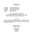
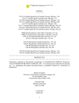
********SERVICE MANUAL*********
MODELS:
75211-50
Gear Pump Drive, w/4-20 mA, 3600 RPM, 115 V
75211-55
Gear Pump Drive, w/4-20 mA, 3600 RPM, 230 V CE
PROPRIETARY
Information contained in this manual is proprietary to the BARNANT COMPANY,
division of COLE-PARMER INSTRUMENT COMPANY, INC. No reproduction for other
than the intended use of maintaining the product described herein is permitted without the
permission of BARNANT.
Barnant Company
Division of Cole-Parmer Instrument Company, Inc.
625 East Bunker Court
Vernon Hills, Illinois 60061-1844
(847)549-7600
(847)247-2929 (Fax)
800-323-4340
A-1299-0985
Edition 02
1
TABLE OF CONTENTS
PAGE
INTRODUCTION…………… ……………………………………………………………….…3
SAFETY CONSIDERATIONS…………………………………………………………………4
THEORY OF OPERATION…………………………………………………………………….5
DETAILED CIRCUIT OPERATION OF CONTROLLER BOARDS……………….……….6
TROUBLESHOOTING……………………………………………………………………….…11
REPAIR PROCEDURES……………………………………………………………………...12
REPLACEMENT PARTS LISTING................................................................................ 14
CALIBRATION PROCEDURE....................................................................................... 15
SPECIFICATIONS ........................................................................................................ 17
2
INTRODUCTION
Service for this product is performed at three levels: the customer, distributor/
COLE-PARMER and factory/depot repair. This manual describes distributor/COLE-PARMER
service procedures.
Customer service procedures are described in the operator’s manual. Customers are
encouraged to perform service as described in the operators manual as well as in special
circumstances where special skills and safety are not considerations.
To use this manual, begin with the troubleshooting section to isolate the fault to a
replaceable part. The functional description and checkout procedure sections are also helpful in
determining the faulty part. Distributor/COLE-PARMER repair is limited to replacement of
modules as detailed in the replacement parts list section. The repair procedure section details
disassembly and assembly procedures. After repair, the product should be calibrated and
checked for proper performance.
Please refer to the operators' manual A-1299-0935 for:
A.) APPLICATIONS DATA
B.) PRODUCT DESCRIPTION
C.) INSTALLATION
D.) SETUP
E.) OPERATION
F.) USER CALIBRATION
G.) USER TROUBLESHOOTING & MAINTENANCE
H.) ACCESSORIES
I.) SPECIFICATIONS
3
SAFETY CONSIDERATIONS
Servicing must be performed only by personnel trained and skilled in the methods of
troubleshooting and repair of electro-mechanical products. Use of procedures other than
those described in this manual may result in a safety hazard to service personnel and/or
customers.
WARNING: High voltage is present inside the unit, when servicing any component
of this unit be absolutely certain that all power to circuitry is removed. If any
functional checks are to be performed while power is applied
and
chassis
is
disassembled, care must be exercised.
CAUTION:
A.) This is a line operated device and is not isolated from ground. Powering the device
under test using an isolation transformer is strongly recommended.
B.) Do not inadvertently short any part of the printed circuit card to ground, as severe
damage will result.
4
THEORY OF OPERATION
The variable speed controller employs a phase-controlled rectifier bridge to vary the
power applied to a permanent magnet DC motor. The bridge will conduct current only
when the power line voltage exceeds the voltage across the motor terminals. Varying the
point at which the bridge starts to conduct relative to the phase of the line voltage can
therefore control the power to the motor. An inner torque, outer speed regulator loop,
controls the phase angle at which the bridge starts conducting. The speed of the motor is
directly proportional to the back EMF generated by the motor. Comparing the voltage
across the motor terminals against the speed reference signal at the center tap of the front
panel speed control pot, an op amp generates a torque reference signal. The torque
supplied by the motor is directly proportional to the current supplied to the motor. The op
amp amplifies the voltage drop across a sense resistor, providing a signal proportional to
the average current supplied to the motor. The peak value of the signal is subtracted from
the torque reference signal by a transistor. The resulting torque error signal charges a
capacitor, firing the power bridge SCR's for a given line cycle.
Transient voltage suppression for the line is provided by “line to line” Mov`s. Motor
brush commutation noise is suppressed using a RC network.
600 volt SCR`s and 1000 volt diodes make up the power bridge and primary power
supply. Supply regulation is through a zener diode network. SCR switching at zero cross is
actually centered on a 10-volt window creating a secondary supply, allowing a complete
shut-off of each SCR. This voltage is also used to synchronize the SCR firing circuit to the
line.
A simple RC network provides for a soft-start circuit, which provides a gentle
acceleration of the motor.
The drives have linear speed control inputs. These two inputs take either 2 – 10 volt
dc or 4 – 20 ma and operate the drive over its full rated speed range.
The linear inputs generate a 1 – 5 volt span that is OP amp buffered for common
mode up to 15 vdc. This voltage is than fed through an offset OP amp to subtract 1 volt
from the signal, leaving 0 – 4 volt control signal for speed reference. MOS switches select
either the front panel control reference voltage or the linear input speed reference to control
drive speed. This stage also incorporates an additional MOS switch that allows contact
closure (start/stop) control of the drive motor. Additional circuitry allows the user to remotely
select the front panel or linear input speed references using a contact closure.
The output of the commanded 4-20 mA and 2-10 VDC inputs are optically isolated from
the ac line, minimum 1250 Vac for 115Vac units, 1900 Vdc for 230Vac units.
5
DETAILED CIRCUIT OPERATION
INTERNAL MODE GENERAL OVER-VIEW
A.) The 75211 series controller board employs modular SMT technology (see figure #1)
to provide a single board solution, employing an SCR based power amplifier to drive
permanent magnet motors.
Power Supply
A.) AC line is brought in at (J-3 and J-4) and routed through (ON:OFF) switch contacts to
power bridge consisting of (CR1,CR2,CR7,CR11).
B.) The rectified voltage at (TP #8), is dropped by series resistor (R26 or R35) and
regulated to approximately 22.7 VDC at (TP #6) by (VR4).
C.) LED connected to J5 indicates power "ON" to circuitry.
D.) Varistor RV1 and RC network R1 & C1 suppress line noise generated externally and
internally by motor and power bridge.
Output Drive
A.) Motor power bridge consists of (CR7, CR11, Q1, Q2). Diode (CR13) bypasses the
inductive current surges of the motor when the Power Bridge shuts off.
B.) Resistor capacitor combination consisting of (R5 and C2) forms a snubber network for
commutation noise suppression.
Control Section
A.) Motor speed is set by front panel pot connected to J6.
B.) A +VREF is obtained by regulating the +22VDC supply with (R34 and VR2) to
approximately +12VDC. This is routed through network (R33 and R30) to DC ground.
Adjustment pot. (R33) sets maximum motor speed approx. +10VDC at (TP-1).
C.) Components (R13, CR9, and C6) control acceleration, deceleration of motor RPM.
D.) Set-speed is controlled and regulated by differential amp (U1) and related components
(R15, C7, R17, and R2, R37, R3). All scaling is done at 5volts full-scale for all op amp
circuits. As motor load increases, back EMF, picked off drive output resistor network
(R2, R37 and R3), (TP-3) increases to 5 volts. This is fed through (R17) to pin 2 of
(U1-A) causing (TP-2) to charge integrator capacitor (C10) via (R18) to advance the
SCR firing angle, until the op amp equalizes its input voltages.
6
E.) Current limit of circuit is accomplished by monitoring the voltage drop of current sense
resistor (R4), feeding it through (R19 and R11) to level amp (U1-B) and related
components. As current through (R4) approaches [2.0 amps for 120 volt units]; [1.0
amps for 240 volt units] voltage to (TP-4) rises to approximately +5.0VDC. This is fed
through resistor network (R22 and R23) at a [2 to 1] ratio, into the peak detector (CR10
& C9). The output of the peak detector is buffered (R21 & Q4) by an emitter follower
(Q4 & R25) amplifier which discharges integrator (C10), retarding the SCR firing angle.
The resultant firing angle will be proportional to the difference between the torque
reference charging current (R18) and the torque feedback discharging current (R25).
F.) The SCR will fire when the integrator (C10) voltage is equal to the "PUT" (Q9) reference
voltage (VR3: R11; & R12). Line synchronization is achieved by allowing the reference
voltage to drop to zero (10-volt window) with each line cross, thereby discharging (C10)
through (Q9). (C10 & Q9) form a relaxation oscillator whose period is proportional to
the rate of charge of (C10). When the voltage across (C10) is equal to the reference
voltage the "PUT" (Q5) is forward biased and will conduct discharging (C-10) through
the base-emitter junction of buffer (Q6). (R9) bypasses any leakage current, while
(C11) filters out noise pulses.
G.) The pulse output of the relaxation oscillator (C10 & Q9) is buffered and amplified by
(Q6) and level shifted by a Darlington pair (Q3 & Q8) on 115-volt units or (Q8 & Q7) on
220-volt units’ fire the Power Bridge SCR (Q1 & Q2). (R7 & R29) limits the gate
current, while (CR6 & CR12) blocks back conduction of the Darlington pair.
H.) For a detailed view of these signals see figure #2 waveform and related
descriptions.
Figure 1 Typical controller board
7
Figure 2
1. Waveform #1 Test point #6
2. Waveform #2 Output of scr bridge across motor
3. Waveform #3 PUT charging ramp test point #5
4. Waveform #4 Motor current measured using TEK #TPC-202 current probe
8
EXTERNAL MODE GENERAL OVER-VIEW
A.) In this mode, the board integrates circuitry from the internal mode with additional
circuitry to allow remote speed control through voltage or current as well as control
through contact closures.
Power Supply
A.) The +22 volt non-isolated supply is derived by a rectified voltage at (TP #8), dropped by
resistor network (R117, R132, R133, R134, R135, R136) these are multiple smt style
resistors and regulated to approximately 22 VDC at (TP #6) by (VR4). The voltage will
charge (C5) through CR8) to filter the ripple and produce a regulated supply.
B.) The +15 volt non-isolated supply is derived by tapping off (C5) through (R33) and
regulated by (VR2). Capacitor (C16) filters any ripple.
C.) A separate +15 volt supply used to drive the circuitry on the isolated side of the circuits
is derived for transformer (T1), rectified by (D1-D4), filtered and bypassed by (C23C24), then fed into regulator (U8). The 15 volts is set by (R106-R107) and filtered by
(C20). This voltage is available at (J16 pin#1).
Control Section
In this controller all user adjustable controls e.g. speed pot and remote features are
isolated from the ac line. The final output from the opto coupler isolator drives the input of
the aforementioned controller.
A.) Motor speed is set by front panel pot connected to J8.
B.) Front panel speed reference voltage is generated by divider network (R65, R56, and
R53) to DC ground. Adjustment pot (R-65) sets maximum motor speed approx.
+4.0VDC at (J16 pin3).
C.) The 4 volt signal that is set above is routed through analog switch network (SW1-A &
SW1C) which is the selection network for front panel speed or remote speed select and
the foot switch control. Switch (SW1-A) works opposite of (SW1-B) when local remote
switch is in the LOCAL position a low is placed at pin5 (SW1-B) turning it off. The low is
prevents conduction of (D8) allowing pull-up (R75) to enable (SW1-A) selecting the front
panel speed reference. When local remote switch is in the REMOTE position a high is
placed at pin5 (SW1-B) turning it on selecting the remote speed inputs. The high causes
conduction of (D8), transistor (Q11) conducts, pulling pin13 (SW1-B) low deselecting
the front panel speed reference. In this mode the user can select either front panel or
remote speed references by grounding (J6 pin4 interface connector).
9
D.) The foot switch control works in a similar manner as above. When local remote switch is
in the REMOTE position a low is placed at pin6 (SW1-B) turning it off. The low is
generated by (Q10) conduction through (D7) pull-up (R70) this prevents the speed
reference voltage (regardless of front panel or remote selection) from driving the opto
coupler isolation drive.
By grounding (J6 pin7 interface connector) the low prevents conduction of (D7),
transistor (Q10) turns off, allowing pull up (R73) to enable (SW1-C) allowing the speed
reference voltage selected to drive the opto coupler isolation drive.
E.) The opto coupler isolation drive consists of (OPT1) and U4-B) this circuit works by
taking a voltage at pin5 (U4-B) and having the output of the op amp drive the input ird
led of (OPT1) until the op amp equalizes its input voltages at pin6. Because there is are
two detectors within opt1 one is within the feedback path, another in a separate op
amplifier (U5-B). A linear drive voltage will give a linear output of the same voltage, pin7
(U5-B). This control voltage typically 0 – 10 volts will drive the SCR amplifier input. This
circuit also serves to provide isolation barrier of approx. 3500 volts between the
grounded and hot referenced control circuits.
F.) The linear inputs consist of (U3-A) dual op amp. This is split one for voltage one for
current. The +voltage input enters pin1 (J6) and ground pin3 (J6) through (R78). The
voltage across R78 is divided by 2 and buffered by (U3-A), to generate a 1 – 5 volt
output. The +current input enters pin2 (J6) and ground pin3 (J6) through (R47). The
voltage across R47 is buffered by (U3-B), to generate a 1 – 5 volt output.
G.) Because the scaling of the electronics the outputs of the above circuits have to start at
“zero” and then span. This is accomplished by setting (U4-A) for an offset of 1 volt. The
result is a 0 – 4 volt control signal.
H.) (D13) is configured as an adjustable zener diode. This will conduct at 6 volts to clamp
off (U3-A) outputs of greater than 5 volts, preventing excessive drive speed.
10
TROUBLESHOOTING
Repairs on this unit are basically confined to either the unit's control PCB and/or the
drive motor assembly.
Where possible, swap "known good" parts to localize and isolate the problem. The
following is a list of possible problems and remedies:
UNIT DOES NOT TURN ON; NO POWER LIGHT:
1.
2.
3.
4.
Fuse blown
Power cord not connected properly
ON-OFF switch failure
Unit connected to dead outlet
-replace fuse
-check & replace
-replace main controller PCB
-verify supply is HOT
UNIT BLOWS FUSES:
1. Motor drive failure
2. Defective controller PCB
3. Wrong fuse installed
-check using known good motor
-replace/return to factory
-check fuse rating
MOTOR WILL NOT RUN: (assumed functional motor)
1. Defective ON-OFF switch
2. Defective controller PCB ASSY.
-replace switch assy.
-Replace main controller PCB ASSY.
LOSS OF SPEED CONTROL OR IMPROPER SPEEDS:
1. Defective controller PCB ASSY.
2. Unit out of calibration
-Replace main controller PCB ASSY.
-recalibrate controller
MOTOR IMMEDIATELY RUNS WHEN POWER IS APPLIED:
1. Power output triacs shorted
-replace main controller PCB ASSY.
For additional information regarding the unit, please refer to the following:
A-1299-0935 operators manual
11
REPAIR PROCEDURES
WARNING: High voltage is present inside the unit, when servicing any component
of this unit be absolutely certain that all power to circuitry is removed. If any
functional checks are to be performed while power is applied and chassis is
disassembled, care must be exercised.
TO DISASSEMBLE UNIT, PROCEED AS FOLLOWS:
A) Remove the three pan head screws on each side of the unit's cover.
B) Carefully unplug all connectors from PCB and separate enclosure assembly from
chassis assembly
TO REPLACE PCB ASSEMBLY:
A)
B)
C)
D)
E)
F)
Remove jackscrews from the DB-9 connector on the back of chassis.
Loosen circuit board guide and slide PC board forward and up.
Disconnect wire leads
Position new PCB in circuit board guide and slide down and back.
Replace the jackscrews on DB-9 connector and tighten the circuit board guide.
Reconnect wire leads from chassis (see TABLE 1)
TABLE1
75211-50
75211-55
GROUND WIRE from ground stud
to: J#15
GROUND WIRE from ground
stud to: J#15
BLUE WIRE from ac line filter to:
J#4
BROWN WIRE from ac line
filter to: J#3
BROWN WIRE from ac line filter to: BLACK/WHITE WIRE from ac
J#3
line filter to: J#4
RED from motor: J#1
RED of motor to: J#1
BLACK from motor: J#2
BLACK of motor to: J#2
POT ASSEMBLY to J#8
POT ASSEMBLY to J#8
LED ASSEMBLY to J#5
LED ASSEMBLY to J#5
SWITCH ASSEMBLY to J#7
SWITCH ASSEMBLY to J#7
G) Check calibration per applicable calibration specification.
12
T0 REPLACE MOTOR
A.) Follow step A in "DISASSEMBLE UNIT".
B.) Remove groundnut and wires from PCB noting wiring.
C.) Loosen motor mounting bolts.
D.) Slide motor forward and remove from chassis.
E.) Install new motor. Reattach ground and motor leads. Slide motor back and tighten
bolts.
TO REPLACE SPEED POTENTIOMETER:
A)
B)
C)
D)
Remove knob and mounting hardware.
Slide pot. assembly out of the control panel.
Install new pot. assembly in reverse sequence.
Verify that when the pot is turned fully counter-clockwise and the indicator knob is
set fully counter clockwise (“0” on the indictor).
TO REPLACE ON-OFF SWITCH:
A.) Remove switch sealing boot, using care to prevent damage to it.
B.) Slide switch assembly out of control panel, noting which side keyway slot on bushing is
facing.
C.) Insert switch assembly into control panel with keyway slot in proper direction, reinstall
boot and tighten until switch will not rotate.
TO REASSEMBLE UNIT, PROCEED AS FOLLOWS:
A) Carefully plug all connectors into PCB observing proper orientation of plugs (see TABLE
1).
B) Reinstall the six pan head screws on the cover of the unit.
13
REPLACEMENT PARTS LISTING
The following is a list of stockable motor assemblies, main control PCB assemblies,
and their reference schematic diagrams for all indicated models:
MODEL #
75211-50
75211-55
-MODELSMAX. RPM
Motor
PCB#
Assembly#
3600RPM; 5992-0001-CR E-2274-0003-CR
115V
3600RPM; 5992-0002-CR E-2274-0004-CR
230V
REFERENCE
SCHEMATIC
E-2268
E-2268
The following is a list of commonly used parts applicable to the above model LISTINGS:
DESCRIPTION
BARNANT
Part#
Speed adjustment knob
ON-OFF switch assembly (115 volt Non-CE models)
ON-OFF switch assembly (230 volt CE models)
Switch sealing boot (all models)
A-2583
7264
7265
A-2984
Speed Pot. Assembly ten turn
T3.15 5 x 20 MM fuse (115V systems)
T1.16 5 x 20 MM fuse (230 V systems)
Rubber foot on chassis
14
5633-0001
B-1115-0057
B-1115-0042
A-1390-0002
CALIBRATION
After repairs are made, the unit must be tested to assure proper performance to
specifications. In many cases servicing personnel to accomplish this can use factory/QC
checkout procedures.
For calibration procedures please refer to the following (CAL-SPECIFICATION)
listings table appropriate to the model that is being serviced.
MODEL#
75211-50
75211-55
CAL-SPECIFICATION #
CAL #1877
CAL #1877
Additional technical specifications are available in the unit's OPERATOR MANUAL.
The following procedure may be used to roughly tweak an out-of-spec. unit.
15
BEFORE PROCEEDING FURTHER PLEASE NOTE ALL WARNINGS AS LISTED IN
THE "SAFETY CONSIDERATIONS SECTION"!!!
------------------------TOOLS REQUIRED
------------------------A.) #1 Phillips screwdriver
B.) Non-metallic pot-tweaker
C.) Hand-held tachometer
-----------------------Proceed as follows:
-----------------------1.) Follow procedure for unit dissasembly.
2.) Plug unit into the appropriate line voltage. If this can be done through an adjustable
variac, to e.g. 115 vac (115 volt units) or 230 vac (230 volt units).
3.) Turn unit on, set speed control for maximum.
4.) Measure & turn pot (R-90) on PC Board to obtain proper motor terminal voltage as
follows:
100.0 vdc +/- .5 vdc (for 115 vac units)
200.0 vdc +/- 1.0 vdc (for 230 vac units)
5.) All other pots are factory adjusted and should not be field adjusted.
6.) Seal pot adjustments and reassemble unit.
16
SPECIFICATIONS
LINE VOLTAGES:
MODEL#
NOM
MIN
MAXIMUM
75211-50
115 volts
90 volts
130 volts
75211-55
230 volts
190 volts
260 volts
LINE FREQUENCY: all models SINGLE PHASE 50/60 hertz
TEMPERATURE & HUMIDITY:
MINIMUM
MAXIMUM
0˚C
40˚C
STORAGE TEMPERATURE:
-25˚C
65˚C
HUMIDITY (NON-COND.):
10%
90%
OPERATING TEMPERATURE:
Remote Start/Stop & Remote/Local
The remote control inputs work with current sinking outputs (open-collector NPN transistor
outputs with or without passive pull-up resistors) or contact closures to DC common (earth
ground). A continuous active low to the Remote Start/Stop input causes the drive to run,
while a continuous active low to the Remote/Local input switches speed control to the front
panel speed control.
High State:
Low State:
Input_Voltage
15 VDC Typ.
0.8 VDC Max.
Input_Current
100 µA Max. leakage
1.5 mA Max.
All inputs will be electrically isolated from the ac line, minimum 1250 Vac for 115Vac units,
1900 Vdc for 230Vac units.
17
Remote Analog Input (Ref.: ISA-S50.1)
4-20 mA Input:
250 ohms typical input impedance referenced to signal ground.
4 mA, Stop; 20 mA, Full Speed
Accuracy: 3% F.S., Linear Resolution
Overload Capability: 10 V or 40 mA max.
2-10 V Input:
10 K ohms typical input impedance referenced to signal ground.
2 V, Stop; 10 V, Full Speed
Accuracy: 3% F.S., Linear Resolution
Overload Capability: 15 V max.
Only one of the analog inputs may be used at any one time. The front end of the circuit is a
differential op amp to allow for multiple units (max 3) to be cascaded in series (Current
Input) or parallel (Voltage Input) for control. Both 4-20 mA and 2-10 VDC inputs are
optically isolated from the ac line, minimum 1250 Vac for 115Vac units, 1900 Vdc for
230Vac units.
18