1
********SERVICE MANUAL*********
MODELS:
-------------7553-70 Variable Speed Drive/Controller System, 600 rpm, 115v
7553-71 Variable Speed Controller only, 600 rpm ,115v
7553-80 Variable Speed Drive/Controller System, 100 rpm, 115v
7553-75 Variable Speed Drive/Controller System, 600 rpm, 230v
7553-76 Variable Speed Controller only, 100 rpm, 230v
7553-77 Variable Speed Drive/Controller System 600 rpm, 230v CE
7553-85 Variable Speed Drive/Controller System, 100 rpm, 230v
7553-87 Variable Speed Drive/Controller System, 100 rpm, 230v CE
50002-02 Stir-pak Heavy-duty Mixer Controller, 115 volt
50002-07 Stir-pak Heavy-duty Mixer Controller, 230 volt
4554-10 Stir-pak Dual-shaft Mixer System, 115 volt
4554-12 Stir-pak Controller only, 115 volt
7144-05 Micropump Variable Speed Drive, 115 volt
7144-07 Micropump Variable Speed Drive, 230 volt
7144-08 Micropump Controller only, 115 volt
7144-09 Micropump Controller only, 230 volt
7593-00 Variable Speed Drive/Controller System, 200 rpm, 115v
7593-05 Variable Speed Drive/Controller System, 200 rpm, 230v
PROPRIETARY
Information contained in this manual is proprietary to the BARNANT COMPANY, division of
COLE-PARMER INSTRUMENT COMPANY, INC. No reproduction for other than the intended
use of maintaining the product described herein is permitted without the permission of
BARNANT.
Barnant Company
Division of Cole-Parmer Instrument Company, Inc.
625 East Bunker Court
Vernon Hills, Illinois 60061-1844
(847)549-7600
(847)247-2929 (Fax)
800-323-4340
A-1299-0437
Edition 06
1
TABLE OF CONTENTS
------------------------------PAGE
SAFETY CONSIDERATIONS.......................................................................................................4
THEORY OF OPERATION............................................................................................................5
DETAILED CIRCUIT OPERATION OF E-2720 & E-2721 PCB’s .......................................... 6-7
DETAILED CIRCUIT OPERATION OF E-2219-XX PCB ASSEMBLIES……………………..8-9
TROUBLESHOOTING.................................................................................................................10
REPAIR PROCEDURES ........................................................................................................ 11-13
REPLACEMENT PARTS LISTING ...................................................................................... 14-16
CALIBRATION PROCEDURE.............................................................................................. 17-18
FUNCTIONAL TEST ...................................................................................................................19
FUNCTIONAL SPECIFICATIONS ....................................................................................... 20-21
2
---------------------------------------------------------------INTRODUCTION
----------------------------------------------------------------
Service for this product is performed at three levels: the customer, distributor/
COLE-PARMER and factory/depot repair. This manual describes distributor/COLE-PARMER
service procedures.
Customer service procedures are described in the operators manual. Customers are
encouraged to perform service as described in the operators manual as well as in special
circumstances where special skills and safety are not considerations.
To use this manual, begin with the troubleshooting section to isolate the fault to a replaceable
part. The functional description and check-out procedure sections are also helpful in determining
the faulty part. Distributor/COLE-PARMER repair is limited to replacement of modules as detailed
in the replacement parts list section. The repair procedures section details disassembly and assembly
procedures. After repair, the product should be calibrated and checked for proper performance.
Please refer to the operators' manual (pt. #A-1299-0484, #A-1299-0472, #A-1299-0555 or
#A-1299-0405) for:
A) APPLICATIONS DATA
B) PRODUCT DESCRIPTION
C) INSTALLATION
D) SETUP
E) OPERATION
F) USER CALIBRATION
G) USER TROUBLESHOOTING & MAINTENANCE
H) ACCESSORIES
I) SPECIFICATIONS
3
---------------------------------------------------------------S A F E T Y C O N S I D E R A T I O NS
---------------------------------------------------------------Servicing must be performed only by personnel trained and skilled in the methods of
troubleshooting and repair of electro-mechanical products. Use of procedures other than those
described in this manual may result in a safety hazard to service personnel and/or customers.
When servicing any component of this unit be absolutely certain that all power to circuitry is
removed. If any functional checks are to be performed while power is applied and chassis is
disassembled, care must be exercised for the following:
WARNING
A) THIS IS A LINE OPERATED DEVICE AND IS NOT ISOLATED FROM GROUND. USE OF
AN ISOLATION TRANSFORMER IS STRONGLY RECOMMENDED.
B) DO NOT INADVERTENTLY SHORT ANY PART OF THE PRINTED CIRCUIT CARD TO
GROUND, AS SEVERE DAMAGE WILL RESULT.
C) MAKE ABSOLUTELY SURE THAT ANY TEST EQUIPMENT USED FOR REPAIR, IS
NOT REFERENCED TO EARTH GROUND.
4
---------------------------------------------------------------THEORY OF OPERATION
---------------------------------------------------------------E-2720 & E-2721 PC Board Assemblies Only
The variable speed controller employs a phase-controlled rectifier bridge to vary the power
applied to a permanent magnet DC motor. The bridge will conduct current only when the power
line voltage exceeds the voltage across the motor terminals. The power to the motor can therefore
be controlled by varying the point at which the bridge starts to conduct, relative to the phase of the
line voltage. The phase angle at which the bridge starts conducting is controlled by an inner torque,
outer speed regulator loop. The speed of the motor is directly proportional to the back EMF
generated by the motor. Comparing the voltage across the motor terminals against the speed
reference signal at the center tap of the front panel speed control pot R-36, U-1 generates a torque
reference signal. The torque supplied by the motor is directly proportional to the current supplied to
the motor. U1 amplifies the voltage drop across a load resistor, providing a signal proportional to
the current supplied to the motor. The peak value of the signal is subtracted from the torque
reference signal by Q4. The resulting torque error signal charges C10, firing Q6 and the power
bridge SCR's.
VR1, R1, and C1 provide transient voltage protection from power line surges caused by other
power conversion equipment and lightning strikes. R5 and C2 provide transient protection from
surges created by motor brush noise and FWD/REV switching.
CR3, CR4, Q1, and Q2 form the main power bridge for the motor. CR5 provides a
current path to allow shut-off of SCR's Q1 and Q2. R2 and R3 provide voltage feedback and R4
provides current feedback to the regulator circuits. CR1 and CR2 with CR3 and CR4 form the
secondary power bridge for the power to the regulator circuits. R26 is a voltage dropping resistor
from line voltage to the +22V used by the regulators. CR7 limits the voltage to +22V. CR6
decouples the pulsating DC, used to synchronize the SCR firing circuit to the line, from the steady
DC, filtered by C5, used to power the regulator circuits. R3 and CR1 stabilize the speed reference
signal.
R11 and R12 provide the voltage reference and line synchronization for the PUT Q5, used to
fire the power bridge SCR's. (CR13 provides a 10 Volt window to allow SCR’s to turn off at each
line cycle.)
R14, CR9, and C6 form the soft-start circuit which provides a gentle acceleration of the
motor.
R31 and R16 compensate for the voltage drop introduced by the motor armature resistance,
thereby improving load regulation of the drive.
CR10 and C09 form a current peak detector which is buffered by R24 and Q04.
Q6 and Q3 form a pulse amplifier and level shifter to fire the power bridge SCR's. The SCR
used for Q3 in the 220 vac units (Q7) is configured to act like a high voltage PNP transistor.
5
---------------------------------------------------------------DETAILED CIRCUIT OPERATION
---------------------------------------------------------------E-2720 & E-2721 PC BOARD ASSEMBLIES
Power Supply
A. AC line is brought in at (J-3 and J-4) and routed through ("FWD:OFF:REV") switch contacts
to power bridge consisting of (CR1-CR4).
B. 100 VDC at (TP #8), is dropped by series resistor (R-26) and regulated to approximately 22.7
VDC at (TP #6) by (CR-7).
C. LED (DS-1) indicates power "ON" to circuitry.
D. Varistor VR1 and RC network R1 & C1 suppress line noise generated externally and internally
by motor and power bridge.
Output Drive
A. Motor power bridge consists of (CR-3, CR-4, Q-1, Q-2). Diode (CR-5) bypasses the inductive
current surges of the motor when the power bridge shuts off. The output bridge is routed
through ("FWD:OFF:REV") switch contacts to allow motor reversal and is brought out at (J-7
and J-4) of the PCB.
B. Resistor capacitor combination consisting of (R-5 and C-2) forms a snubber network for
commutator noise suppression.
Control Section
A. Motor speed is set by front panel pot (R-29).
B. A +VREF is obtained by regulating the +22VDC supply with (R-13 and CR-11) to
approximately +12VDC. This is routed through network (R-28 and R-29) to DC ground.
Adjustment pot. (R-28) sets maximum motor speed approx. +10VDC at (TP-1).
C. Components (R-14, CR-9, C-6) control acceleration, deceleration of motor RPM.
D. Set-speed is controlled and regulated by differential amp (U1) and related components (R-15,
C-7, R-17, R-2, R-3). As motor load increases, back EMF, picked off drive output resistor
network (R-2 and R-3), (TP-3) drops off. This is fed through (R-17) to pin 2 of (U1-A) causing
(TP-2) to charge integrator capacitor (C-10) via (R-18) to advance the SCR firing angle.
E. Current limit of circuit is accomplished by monitoring the voltage drop of current sense
resistor (R-4), feeding it through (R-19 and R-20) to level amp (U1-B) and related components.
As current through (R-4) approaches [2.0 amps for 120 volt units];[ 1.0 amps for 240 volt
units] voltage to (TP-4) rises to approximately +4.0VDC. This is fed through resistor network
(R-22 and R-23) at a [2 to 1] ratio, into the peak detector (CR-10 & C-9).The output of the peak
detector is buffered (R-24 & Q-4) by an emitter follower (Q-4 & R-25) amplifier which
6
discharges integrator (C-10), retarding the SCR firing angle. The resultant firing angle will
be proportional to the difference between the torque reference charging current (R-18) and the
torque feedback discharging current (R-25).
F. The SCR will fire when the integrator (C-10) voltage is equal to the"PUT" (Q-5) reference
voltage (CR-7;R-11;&R-12). Line synchronization is achieved by allowing the reference
voltage to drop to zero with each line cross, thereby discharging (C-10) through (Q-5). (C-10 &
Q-5) form a relaxation oscillator whose period is proportional to the rate of charge of (C-10).
When the voltage across (C-10) is equal to the reference voltage, the "PUT"(Q-5) is forward
biased and will conduct, discharging (C-10) through the base-emitter junction of buffer (Q-6).
(R-9) by-passes any leakage current, while (C-11) filters out noise pulses.
G. The pulse output of the relaxation oscillator (C-10 & Q-5) is buffered and amplified by (Q-6)
and level shifted by a Darlington pair (Q-3 & Q-8) on 115 volt units or (Q-8 & Q-7) on 220 volt
units fire the power bridge SCR (Q-1 & Q-2). (R-7) limits the gate current, while (CR-6 &
CR-12) blocks back conduction of the Darlington pair.
7
---------------------------------------------------------------DETAILED CIRCUIT OPERATION
---------------------------------------------------------------E-2219 PC BOARD ASSEMBLY
Power Supply
A. AC line is brought in at (J-3 and J-4) and routed through ("FWD:OFF:REV") switch contacts
to power bridge consisting of (CR1-CR4).
B. 100 VDC at (TP #8), is dropped by series resistor (R-26) and regulated to approximately 22.7
VDC at (TP #6) by (CR-7).
C. LED (DS-1) indicates power "ON" to circuitry.
D. Varistor VR1 and RC network R1 & C1 suppress line noise generated externally and internally
by motor and power bridge.
Output Drive
A. Motor power bridge consists of (CR-3, CR-4, Q-1, Q-2). Diode (CR-5) bypasses the inductive
current surges of the motor when the power bridge shuts off. The output bridge is routed
through ("FWD:OFF:REV") switch contacts to allow motor reversal and is brought out at (J-1
and J-2) of the PCB.
B. Resistor capacitor combination consisting of (R-5 and C-2) forms a snubber network for
commutator noise suppression.
Control Section
A. Motor speed is set by front panel pot connected to J6.
B. A +VREF is obtained by regulating the +22VDC supply with (R-13 and CR-11) to
approximately +12VDC. This is routed through network (R-33 and R-30) to DC ground.
Adjustment pot. (R-33) sets maximum motor speed approx. +10VDC at (TP-1).
C. Components (R-13, CR-9, C-6) control acceleration, deceleration of motor RPM.
D. Set-speed is controlled and regulated by differential amp (U1) and related components (R-15,
C-7, R-17, R-2, R-37, R-3). As motor load increases, back EMF, picked off drive output
resistor network (R-2, R-37 and R-3), (TP-3) drops off. This is fed through (R-17) to pin 2 of
(U1-A) causing (TP-2) to charge integrator capacitor (C-10) via (R-18) to advance the SCR
firing angle.
E. Current limit of circuit is accomplished by monitoring the voltage drop of current sense
resistor (R-4), feeding it through (R-19 and R-11) to level amp (U1-B) and related components.
As current through (R-4) approaches [2.0 amps for 120 volt units];[ 1.0 amps for 240 volt
units] voltage to (TP-4) rises to approximately +4.0VDC. This is fed through resistor network
(R-22 and R-23) at a [2 to 1] ratio, into the peak detector (CR-10 & C-9).The output of the peak
8
detector is buffered (R-21 & Q-4) by an emitter follower (Q-4 & R-25) amplifier which
discharges integrator (C-10), retarding the SCR firing angle. The resultant firing angle will
be proportional to the difference between the torque reference charging current (R-18) and the
torque feedback discharging current (R-25).
F. The SCR will fire when the integrator (C-10) voltage is equal to the"PUT" (Q-9) reference
voltage (VR-3:R-11;&R-12). Line synchronization is achieved by allowing the reference
voltage to drop to zero with each line cross, thereby discharging (C-10) through (Q-9). (C-10 &
Q-9) form a relaxation oscillator whose period is proportional to the rate of charge of (C-10).
When the voltage across (C-10) is equal to the reference voltage, the "PUT"(Q-5) is forward
biased and will conduct, discharging (C-10) through the base-emitter junction of buffer (Q-6).
(R-9) by-passes any leakage current, while (C-11) filters out noise pulses.
G. The pulse output of the relaxation oscillator (C-10 & Q-9) is buffered and amplified by (Q-6)
and level shifted by a Darlington pair (Q-3 & Q-8) on 115 volt units or (Q-8 & Q-7) on 220 volt
units fire the power bridge SCR (Q-1 & Q-2). (R-7 & R-29) limits the gate current, while (CR-6
& CR-12) blocks back conduction of the Darlington pair.
9
---------------------------------------------------------------TROUBLESHOOTING
----------------------------------------------------------------Repairs on this unit are basically confined to either the unit's control PCB and/or the drive
motor assembly.
Where possible, swap "known good" parts to localize and isolate the problem. The
following is a list of possible problems and remedies:
UNIT DOES NOT TURN ON; NO POWER LIGHT:
1.
2.
3.
4.
fuse blown
power cord not connected properly
FWD-OFF-REV switch failure
unit connected to dead outlet
-replace fuse
-check & replace
-replace main controller PCB
-verify supply is HOT
UNIT BLOWS FUSES:
1. motor drive failure
2. defective controller pcb
3. wrong fuse installed
-check using known good motor
-replace/return to factory
-check fuse rating
MOTOR WILL NOT REVERSE:
1. defective FWD-OFF-REV switch
-replace switch assy.
MOTOR WILL NOT RUN: (assumed functional motor)
1. defective FWD-OFF-REV switch
2. defective controller PCB ASSY.
-replace switch assy.
-replace main controller PCB ASSY.
LOSS OF SPEED CONTROL OR IMPROPER SPEEDS:
1. defective controller PCB ASSY.
2. unit out of calibration
-replace main controller PCB ASSY.
-recalibrate controller
MOTOR IMMEDIATELY RUNS WHEN POWER IS APPLIED:
1. power output triacs shorted
-replace main controller PCB ASSY.
For additional information regarding the unit, please refer to the following:
A-1299-0484 operators manual
A-1299-0472 operators manual
A-1299-0405 operators manual
A-1299-0550 operators manual
10
----------------------------------------------------------------REPAIR PROCEDURES
---------------------------------------------------------------(7144 SERIES PRIOR TO 8/94)
TO DISASSEMBLE UNIT, PROCEED AS FOLLOWS:
A)
B)
C)
D)
E)
F)
Remove speed adjust knob from front panel.
Remove mounting hardware from potentiometer.
Remove control switch sealing boot from panel.
Remove the four pan head screws on the bottom of the unit.
Remove the four pan head screws holding the PCB assembly to the front panel.
Remove PCB assembly by gently pulling straight out.
TO REASSEMBLE UNIT, PROCEED AS FOLLOWS:
A)
B)
C)
D)
E)
F)
Install PCB assembly by placing into top cover.
Install the four pan head screws holding the PCB assembly.
Install control switch sealing boot to panel.
Install potentiometer mounting hardware.
Install speed adjust knob.
Verify that when speed adjust knob is turned fully counter-clockwise, that indicator line is
directly above screened line on front panel.
G) Install the four pan head screws on bottom of unit.
TO REPLACE MAIN CONTROL PCB ASSEMBLY:
A) Follow the steps outlined in "DISASSEMBLE UNIT".
B) Replace main PCB assembly.
C) Note wiring of chassis as follows:
115 volt Models
230 volt Models
BLACK from ac line cord to: J#3
BROWN of power shell to: J#3
WHITE from ac line cord to: J#4
BLUE of power shell to: J#4
ORANGE from motor socket to: J#2
ORANGE of motor socket to: J#2
WHITE from motor socket to: J#1
WHITE of motor socket to: J#1
D) Check calibration as per applicable CAL. specifications.
E) Follow the steps outlined in "ASSEMBLE UNIT".
---------------------------------------------------------------11
REPAIR PROCEDURES
---------------------------------------------------------------(7553, 7593, 50002, 7144 & 4554 SERIES AS of 8/94)
TO DISASSEMBLE UNIT, PROCEED AS FOLLOWS:
A) Remove four pan head screws on bottom of controller.
B) Carefully unplug all connectors from PCB and separate enclosure assembly from chassis
assembly.
TO REPLACE PCB ASSEMBLY:
A) Depress locking taps on PCB stand-offs and remove PCB.
B) Position new PCB over stand-offs and place slight pressure on corners of PCB until it snaps
down on stand-offs.
C) Reconnect four wire leads from chassis as follows:
115 volt Models
230 volt Models
BLACK from ac line cord to: J#3
BROWN of power shell to: J#3
WHITE from ac line cord to: J#4
BLUE of power shell to: J#4
ORANGE from motor socket to: J#2
ORANGE of motor socket to: J#2
WHITE from motor socket to: J#1
WHITE of motor socket to: J#1
D) Check calibration per applicable calibration specification.
TO REPLACE LED ASSEMBLY:
A) Using a small flat blade screwdriver, gently pry open plastic tabs on LED assembly that hold
lens to control panel.
B) Lift lens out of control panel taking care not to lose or damage gasket.
C) Install new assembly by sliding gasket on lens and inserting lens into panel.
D) Hold lens against panel firmly and insert LED assembly into lens and apply pressure towards
lens until taps lock on lens.
TO REPLACE SPEED POTENTIOMETER:
A)
B)
C)
D)
Remove knob and mounting hardware.
Slide pot. assembly out of the control panel taking care not to lose the gasket.
Install new pot. assembly in reverse sequence.
Verify that when the knob is turned fully counter-clockwise, the indicator line is directly
above screened line on control panel.
TO REPLACE FWD-OFF-REV SWITCH:
12
A) Remove switch sealing boot, using care to prevent damage to it.
B) Slide switch assembly out of control panel, noting which side keyway slot on bushing is facing.
C) Insert switch assembly into control panel with keyway slot in proper direction, reinstall boot and
tighten until switch will not rotate.
TO REASSEMBLE UNIT, PROCEED AS FOLLOWS:
A) Carefully plug all connectors into PCB observing proper orientation of plugs.
B) Reinstall the four pan head screws on the bottom of the unit.
13
----------------------------------------------------------------REPLACEMENT PARTS LISTING
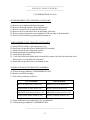
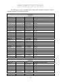
----------------------------------------------------------------The following is a list of stockable main control PCB assemblies, and their reference
schematic diagrams for all indicated models:
MODEL #
7553-70
7553-70
7553-70
7553-71
7553-71
7553-71
7553-80
7553-80
7553-80
7593-00
7593-00
50002-02
50002-02
50002-02
7144-05
7144-05
7144-05
7144-08
7144-08
7144-08
4554-10
4554-10
4554-10
4554-12
4554-12
4554-12
MODEL #
7553-75
7553-75
7553-75
7553-76
7553-76
7553-76
7553-85
As of 8/94
As of 6/99
As of 8/94
As of 6/99
As of 8/94
As of 6/99
As of 8/94
As of 6/99
As of 8/94
As of 6/99
As of 8/94
As of 6/99
As of 8/94
As of 6/99
As of 8/94
As of 6/99
As of 8/94
As of 6/99
As of 8/94
As of 6/99
As of 8/94
As of 6/99
---115 volt---MODELSPCB#
REFERENCE SCHEMATIC
D-2461-0001
D-2655
D-2720-0001
D-2736
E-2219-0001
E-2193
D-2461-0001
D-2655
D-2720-0001
D-2736
E-2219-0001
E-2193
D-2461-0001
D-2655
D-2720-0001
D-2736
E-2219-0001
E-2193
D-2720-0001
D-2736
E-2219-0001
E-2193
D-2461-0001
D-2655
D-2720-0001
D-2736
E-2219-0001
E-2193
D-2465-0002
D-2463
D-2720-0003
D-2736
E-2219-0004
E-2193
D-2465-0001
D-2463
D-2720-0003
D-2736
E-2219-0004
E-2193
D-2641-0002
D-2669
D-2720-0002
D-2736
E-2219-0003
E-2193
D-2641-0002
D-2669
D-2720-0002
D-2736
E-2219-0003
E-2193
---230 volt---MODELSPCB#
REFERENCE SCHEMATIC
D-2656-0001
D-2655
D-2721-0001
D-2736
E-2219-0002
E-2193
D-2656-0001
D-2655
D-2721-0001
D-2736
E-2219-0002
E-2193
D-2656-0001
14
D-2655
7553-85
7553-85
7593-05
7593-05
50002-07
50002-07
50002-07
7144-07
7144-07
7144-07
7144-09
7144-09
7144-09
7553-77
7553-77
7553-87
7553-87
As of 8/94
As of 6/99
As of 8/94
As of 6/99
As of 8/94
As of 6/99
As of 8/94
As of 6/99
As of 8/94
As of 6/99
As of 6/99
As of 6/99
D-2721-0001
E-2219-0002
D-2721-0001
E-2219-0002
D-2656-0001
D-2721-0001
E-2219-0002
D-2491-0002
D-2721-0002
E-2219-0005
D-2491-0002
D-2721-0002
E-2219-0005
D-2721-0001
E-2219-0002
D-2721-0001
E-2219-0002
D-2736
E-2193
D-2736
E-2193
D-2655
D-2736
E-2193
D-2463
D-2736
E-2193
D-2463
D-2736
E-2193
D-2736
E-2193
D-2736
E-2193
-CONTINUED-
15
The following is a list of commonly used parts applicable to the above model LISTINGS:
DESCRIPTION
BARNANT Part#
speed adjustment knob (7144) Prior to 8/94
B-1083-0052
switch sealing boot (7144) Prior to 8/94
A-4050
rubber foot small (7144) Prior to 8/94
A-1390-0001
ON-OFF switch assembly (7144)
B-3431
FWD-OFF-REV switch assembly (7553, 50002, 4554 & 7593)
(Non-CE models)
B-3281
switch sealing boot (7553, 50002, 4554, 7144 & 7593)
A-2984
rubber foot large (7553, 50002, 4554, 7144 & 7593)
A-1390-0002
speed adjustment knob (7553, 50002, 4554, 7144 & 7593)
B-1083-0035
LED assembly (7553, 50002, 4554, 7144 & 7593)
A-4270
speed pot. assembly (7553, 50002, 4554, 7144 & 7593)
A-4268
LED gasket (7553, 50002, 4554, 7144 & 7593)
A-4272
speed pot. gasket (7553, 50002, 4554, 7144 & 7593)
A-4271
FWD-OFF-REV SW. Assembly (7553-77, 87)(CE models only)
D-2906
16
---------------------------------------------------------------CALIBRATION
---------------------------------------------------------------After repairs are made, the unit must be tested to assure proper performance to
specifications. In many cases factory/QC check-out procedures can be used by servicing personnel
to accomplish this.
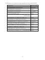
For calibration procedures please refer to the following (CAL-SPECIFICATION) listings
table appropriate to the model that is being serviced.
MODEL#
CAL-SPECIFICATION #
MODEL#
CAL-SPECIFICATION#
7553-70
CAL.#1316
50002-02
CAL.#1332
7553-71
CAL.#1316
50002-07
CAL.#1332
7553-80
CAL.#1316
7553-75
CAL.#1316
4554-10
CAL.#1509
7553-76
CAL.#1316
4554-12
CAL.#1509
7553-85
CAL.#1316
7553-77
CAL.#1316
7144-05
CAL.#1609
7553-87
CAL.#1316
7144-07
CAL.#1609
7593-00
CAL.#1316
7144-08
CAL.#1609
7593-05
CAL.#1316
7144-09
CAL.#1609
Additional technical specifications are available in the unit's OPERATOR MANUAL.
Because this manual is covering approximately 14 different models, exact calibration
procedures will differ between each unit. However the following procedure may be used to roughly
calibrate an out-of-spec. unit.
17
BEFORE PROCEEDING FURTHER PLEASE NOTE ALL WARNINGS AS LISTED IN THE
"SAFETY CONSIDERATIONS SECTION"!!!
------------------------TOOLS REQUIRED
------------------------A) #1 Phillips screwdriver
B) Non-metallic pot-tweaker
C) Hand-held tachometer
-----------------------Proceed as follows:
-----------------------1)
2)
3)
4)
Remove the four pan-head screws at the bottom of the unit.
Position top half of cover so that adjustment pots are accessible.
Connect drive motor to controller.
Plug unit into the appropriate line voltage. If this can be done through an adjustable variac, to
e.g. 115 vac (115 volt units) or 230 vac (230 volt units).
5) Turn unit on, set speed control for maximum.
6) Measure & turn pot (R-28) E-2720 & E-2721 series PC Boards; (R-33) E-2219 series
(multi-turn) to obtain proper motor terminal voltage as follows:
100.0 vdc +/- .5 vdc (for 115 vac units)
90.0 vdc +/- .5 vdc (4554-10, 4554-12)
200.0 vdc +/- 1.0 vdc (for 230 vac units)
7) Pot (R-31) E-2720 &E-2721 series PC Boards; (R-36) E-2219 series is used to set the units
no-load to full-load response and therefore should not be field adjusted.
8) Seal pot adjustments and reassemble unit.
18
---------------------------------------------------------------FUNCTIONAL TESTS
---------------------------------------------------------------A) Mate drive motor to specified controller.
B) Power up controller at specified line voltage.
C) Verify that controller drives motor properly.
D) Refer to the "CALIBRATION" Section for additional information regarding the controller.
19
---------------------------------------------------------------SPECIFICATIONS
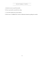
--------------------------------------------------------------------------------------LINE VOLTAGES:
-----------------------MODEL#
NOM
MIN
MAXIMUM
7553-70
115 volts
90 volts
130 volts
7553-71
115 volts
90 volts
130 volts
7553-80
115 volts
90 volts
130 volts
7553-75
115 volts
90 volts
130 volts
7593-00
115 volts
90 volts
130 volts
50002-02
115 volts
90 volts
130 volts
4554-10
115 volts
90 volts
130 volts
4554-12
115 volts
90 volts
130 volts
7144-05
115 volts
90 volts
130 volts
7144-08
115 volts
90 volts
130 volts
7553-75
230 volts
190 volts
260 volts
7553-76
230 volts
190 volts
260 volts
7553-86
230 volts
190 volts
260 volts
7593-05
230 volts
190 volts
260 volts
50002-07
230 volts
190 volts
260 volts
7144-07
230 volts
190 volts
260 volts
7144-09
230 volts
190 volts
260 volts
7553-77
230volts
190 volts
260 volts
7553-87
230 volts
190 volts
260 volts
-------------------------LINE FREQUENCY: all models SINGLE PHASE 50/60 hertz
--------------------------
20
----------------------------------------TEMPERATURE & HUMIDITY:
----------------------------------------MINIMUM
MAXIMUM
0C
40C
STORAGE TEMPERATURE:
-45C
65C
HUMIDITY (NON-COND.):
10%
90%
OPERATING TEMPERATURE:
----------------------CODE RATINGS:
----------------------All controller housings meet INTERNATIONAL ELECTRIC CODE 34-5 & 529 (IP-CODE) 53
RATING.
(SIMILAR TO NEMA 5 AND 12 RATINGS)
21