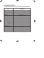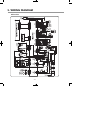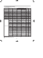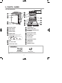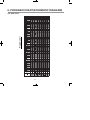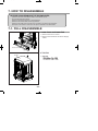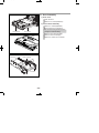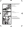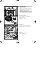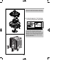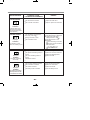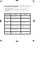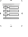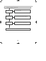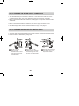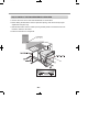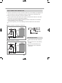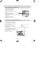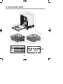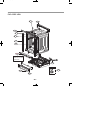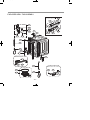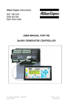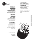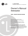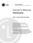
1
MFL37554808(S/M)
2009.2.5 8:54 AM
˘
` 2
‰¯¿ł– •¡˙¨‰”
DISHWASHER
SERVICE MANUAL
NOTE
BEFORE SERVICING THE UNIT, PLEASE READ THIS MANUAL CAREFULLY
FOR SAFETY AND CORRECT SERVICES.
MODEL : LDF9932(WW,BB,ST) / LSDF995ST
MFL37554808(S/M)
2009.2.5 8:54 AM
˘
` 3
‰¯¿ł– •¡˙¨‰”
CONTENTS
1. CAUTION......................................................................................................................... 4
2. SPECIFICATIONS ........................................................................................................... 5
3. WIRING DIAGRAM........................................................................................................ 6
4. FEATURES & TECHNICAL EXPLANATION ................................................................... 7
5. PARTS NAME ................................................................................................................ 11
6. PROGRAM CHART ..................................................................................................... 12
7. HOW TO DISASSEMBLE ............................................................................................ 13
8. TROUBLE SHOOTING METHODS .............................................................................. 22
A. TROUBLE SHOOTING ACCORDING TO DISPLAYED ERROR MESSAGE...........22
B. STEAM GENERATOR ERROR MESSAGE ............................................................ 24
C. TROUBLE DIAGNOSES AND REPAIR BY SYMPTOM .......................................... 25
9. INSTALLATION INSTRUCTION ................................................................................... 29
10. EXPLODED VIEW .......................................................................................................36
-3-
MFL37554808(S/M)
2009.2.5 8:54 AM
˘
` 4
‰¯¿ł– •¡˙¨‰”
CAUTION !
DISCONNECT POWER CORD BEFORE SERVICING
RECONNECT ALL GROUNDING DEVICES
IMPORTANT SAFETY NOTICE !
This service information is intended for individuals
possessing adequate backgrounds of electrical,
electronic and mechanical experience.
Any attempt to repair this appliance may result in
personal injury and property damage.
The manufacturer or seller can not be responsible
for the interpretation of this information, nor can it
assume any liability in connection with its use.
-4-
MFL37554808(S/M)
2009.2.5 8:54 AM
˘
` 5
‰¯¿ł– •¡˙¨‰”
2. SPECIFICATION
SPECIFICATION
ITEM
Rated Voltage / Frequency
AC 120V/60Hz
Installation
Built-In
Place Settings
14
Product Dimension(in)
23 3/4"x 24 5/8"x 33 1/2"
Product Weight(lbs)
114lbs
Door Color
White, Black, Stainless
Tub Material
Stainless Steel
Control
Electronic
Rated Power(Watt)
1,350
Heater Power(Watt)
1,200
Programs
6
Upper Rack Position
Adjustable
Lower Rack
50% Fold down
Water Consumption
10-26 (Normal)
Power Consumption(kWh/year)
285-310
Operating Time (min)
97-124 (Normal)
Fan Dry System
Yes
Delay Start Function
Yes
Auto-Off Power Switch
Yes
Process Monitor
Yes
Wash Level
5
Racks
Nylon Coating
Operating Water Pressure (Bar)
20-120 (140-830kPa)
-5-
MFL37554808(S/M)
2009.2.5 8:54 AM
˘
` 6
‰¯¿ł– •¡˙¨‰”
3. WIRING DIAGRAM
9932 series
-6-
MFL37554808(S/M)
2009.2.5 8:54 AM
˘
` 7
‰¯¿ł– •¡˙¨‰”
4. FEATURES & TECHNICAL EXPLANATION
4-1. Product Features
LARGE CAPACITY
VARIO SPRAY SYSTEM
LG dishwashers allow you to load very large
items in both the upper
and lower racks. The
tall tub provides extra
overall capacity and
the clearance to
accommodate large
dishes. Extra large items
(max. 14 in.) may be
loaded in the lower rack
by raising the upper rack.
Because the water spray alternates between the
upper and lower racks,
all of the power from
the motor is directed
to one rack at a time.
This concentrates all
the cleaning power of
the motor on each rack
in turn.
SOFT FOOD GRINDER AND
SELF-CLEANING FILTER
For best wash results, your LG dishwasher has
a built-in soft food
grinder and a selfcleaning filter. The
grinder grinds up soft
food and residue into
small particles that can
be caught in the filter
and washed down the
drain. The self-cleaning
filter system continuously cleans the wash water
as it circulates to separate any residue from the
wash water. All dirt and residue is easily washed
down the drain.
SLIM DIRECT MOTOR™
The new Slim Direct Motor™ is invertercontrolled. Wash
power is controlled
based on cycle
selection. It also
offers high energy
efficiency to minimize
energy use.
HYBRID DRYING SYSTEM
This system effectively dries dishes without the
use of a heating
element that would
increase energy
consumption.
LIGHT TOUCH BUTTONS AND BLUE LCD
The light touch buttons on the control panel make
selections easy and
convenient, while the
blue LCD display
clearly displays the
selected cycle and
options.
STEAM WASHING
REMOVABLE CUTLERY RACK
Steam technology provides better cleaning
performance than
regular wash systems.
Steam is the most
energy efficient gentle
care for your finest
china and stemware.
Third level cutlery rack
makes it easy to load and
unload flatware and cooking
utensils.
Trays can be adjusted or
removed to make more room for regular upper
rack items.
-7-
MFL37554808(S/M)
2009.2.5 8:54 AM
˘
` 8
‰¯¿ł– •¡˙¨‰”
4-2. Display Panel LDF 7932 Series
Control panel may vary on some models.
1
2
CHIME ON/OFF
1 CYCLES
Press the cycle that corresponds to your desired wash
cycle.
To enable or disable the chime, press and hold the
Quick Wash and Rinse buttons for 2 seconds.
POWER SCRUB
RINSE ONLY
This cycle is a quick rinse for dishes that will not be
washed immediately. No detergent should be used.
To select the Rinse Only cycle, press the Power
button; then press the Rinse button once without
pressing any other cycle buttons.
This cycle is for very heavily soiled dishes.
NORMAL
This cycle is for normally soiled, everyday loads.
DUAL INTENSITY
This cycle washes the upper and lower racks at different
spray intensities. The default setting for this cycle washes
the lower rack with strong spray intensity and the upper
rack with soft spray intensity. This provides optimum
cleaning performance for mixed loads, including fine
china and stemware. If other combinations are desired,
use the steps listed below to change the intensities or to
use the HALF LOAD feature.
How To Use Dual Intensity
1. Press and hold the SPRAY button for three seconds until
the UPPER light begins to blink.
2. While the UPPER light is blinking, press the SPRAY
button until the desired intensity for the upper rack is
selected.
3. Press the HALF LOAD button to switch to the lower rack
and use the SPRAY button to adjust to the desired
intensity.
4. Selections can be cancelled by selecting any cycle except
QUICK WASH
This is a shortened cycle that is perfect for recently used
or lightly soiled loads.
STEAM DELICATE
This cycle adds the gentle power of steam to boost the
cleaning power of the delicate cycle. The cycle is perfect
for effectively cleaning delicate items like fine china or
stemware.
STEAM FRESH
This cycle can be used to freshen up dishes that may
have been stored or not used for a long time.
-8-
NOTE: If a main cycle has been selected, the Rinse
Only cycle will not be available without first shutting
the power off.
2 CANCEL
To cancel a running cycle, open the door and then
press and hold the Dual Intensity and Quick Wash
buttons together for 3 seconds. The drain pump
will be activated and the cycle will be cancelled.
3 CYCLE OPTIONS AND DISPLAY
Press the desired cycle option buttons to select
and set any of the dishwasher’s options described
below. The display will show the selected cycle times
and cycle options.
SPRAY (INTENSITY)
Repeated pressing of the Spray button will select the
desired spray. The strong, medium, or soft light will
show in the top left portion of the display.
Soft (
), Medium (
), Strong (
)
RINSE
Repeated pressing of the Rinse button will select the
desired Rinse option. The Sanitary, Extra Rinse, or
Sanitary and Extra Rinse lights will show in the
bottom left portion of the display.
EXTRA RINSE(
), SANITARY(
)
MFL37554808(S/M)
2009.2.5 8:54 AM
˘
` 9
‰¯¿ł– •¡˙¨‰”
3
4
• If you select the Sanitary feature, the Sanitary light
will blink until the water is heated to the sanitary
temperature level*. Once the sanitary temperature
level is reached, the light will stay on to indicate
that the sanitary temperature has been reached.
*NOTE: This high-temperature rinse sanitizes
dishware and glassware in accordance with
NSF/ANSI Standard 184 for residential
dishwashers. Certified dishwashers are not
intended for licensed food establishments.
• When you select Extra Rinse, an additional
rinse cycle is added.
• Rinse Only is a wash cycle described on
the previous page.
CHILD LOCK
Lamp will turn on when Child Lock
setting is on.
• To lock/unlock the buttons, press and hold the
Delicate and Rinse Only Buttons simultaneously
for 3 seconds with the door open.
• Lock the control buttons during cycle operation to
prevent settings from being changed.
RINSE AID
HALF LOAD
• For small loads, you may use just the upper or
lower rack to save energy.
• Each press of the Half Load button cycles
berween upper rack only and lower rack only.
• If Half Load is not pressed, the dishwasher will
run normally, with upper and lower spray arms
operating alternately.
DELAY START
• To delay the start of a selected cycle, press
the Delay Start button.
• Each time Delay Start is pressed will delay
the start of the cycle by one additional hour.
• The delay start time can be set from 1 to 12
hours in one-hour increments.
STEAM
• Press the Steam button to add steam to a
selected cycle.
• The Steam symbol will be lighted on when the
STEAM option has been selected.
• The steam symbol will blink while steam is being
injected into the dishwasher.
wWARNING
Refill with rinse aid when the lamp
turns on.
DIGITAL DISPLAY
The Digital Display on the control
panel shows the estimated cycle and
option times.
When the dishwasher is powered up, the display will
be blank. When the cycle and options are selected,
the display will show the total estimated time to
complete those selections. During operation, the
display shows the remaining estimated operating
time.
NOTES:
• The estimated time shown in the display does not
include delay times for heating water, etc.
• If Delay Wash is selected, the display shows the
delay time in hours.
-9-
Steam can cause burns. Use caution in
the area of the steam nozzle on the left
side of the dishwaher if the door is opened
during the steam portion of a cycle.
Contact with the steam or the steam nozzle
can cause burns.
4 POWER
• Pressing the Power button turns on power
to the controls.
• After the cycle is complete, the power
automatically turns off for safety and economy.
• If there is a power surge, power outage,
or disruption of any kind, the power will be
automatically turned off for safety, and the
cycle will need to be restarted.
MFL37554808(S/M)
2009.2.5 8:54 AM
˘
` 10
‰¯¿ł– •¡˙¨‰”
4-3. TEST MODE LDF 7932 Series
CHECK PROGRAM
Load and Checking points
Load
LED lighting
Door open/
Remark
closed
BUTTON
The number of
pushing button
Top
Display
STEAM+RINSE+
POWER Buttonn
1 TIME
0n:3H/ 0U:00
All LEDs are lighting
Either
POWER SCRUB
1 TIME
00:00
All LEDs are lighting
Either
NORMAL
1 TIME
11:11
All LEDs are lighting
Either
DUAL INTENSITY
1 TIME
22:22
All LEDs are lighting
Either
QUICK WASH
1 TIME
33:33
All LEDs are lighting
Either
STEAM DELICATE
1 TIME
44:44
All LEDs are lighting
Either
STEAM FRESH
1 TIME
55:55
All LEDs are lighting
Either
STEAM
1 TIME
66:66
All LEDs are lighting
Either
RINSE
1 TIME
77:77
All LEDs are lighting
Either
SPRAY
1 TIME
88:88
All LEDs are lighting
Either
HALF LOAD
1 TIME
All LEDs are lighting
Either
1 TIME
99:99
Steam generator
Temp( )
Steam generator
Thermistor
All LEDs
Either
2 TIME
0n:H1
Steam generator
Heater (for 1.2 sec)
All LEDs
Closed
3 TIME
0n:33
Drain Pump
All LEDs
Either
See Test 3
4 TIME
Frequency
Inlet Valve
All LEDs
Closed
See Test 4
5 TIME
0n:35
Dispenser
All LEDs
Closed
See Test 5
6 TIME
0n:36
Sump Heater
(for 10 sec)
All LEDs
Closed
See Test 6
7 TIME
0n:37
Fan Motor
All LEDs
Closed
See Test 7
8 TIME
0n:38
All LEDs
Closed
9 TIME
Sump Temp( )
Sump Thermistor
All LEDs
Either
10 TIME
Soil level
Soil sensor
All LEDs
Either
11 TIME
0n:3b/Motor RPM
Wash Pump
All LEDs
Closed
12 TIME
Steam generator
Water level
Water level
All LEDs
Either
13 TIME
0n:3d
Lower Nozzle
(Vario)
All LEDs
Closed
See Test 8
14 TIME
0n:3E
Upper Nozzle
(Vario)
All LEDs
Closed
See Test 8
15 TIME
0n:3F
(RPM,Frequency)
W/Pump+Vario+
Heater (for 1min)
All LEDs
Closed
DELAY START
Auto-Off
16 TIME
Normal water level : 270 ~ 275
Pure water : more than 130
H: High water level / L: Low water level
See Test 1
Closed
Steam Demo mode : Steam + Power
- 10 -
MFL37554808(S/M)
2009.2.5 8:54 AM
˘
` 11
‰¯¿ł– •¡˙¨‰”
5. PARTS NAME
5-3. LDF 9932 Series
14
15
6
1
7
2
8
16
9
3
17
10
4
11
5
12
18
19
20
13
1 CONTROL PANEL
10 STEAM NOZZLE
2 DOOR HANDLE
11 LOWER SPRAY ARM
3 FRONT COVER
12 DETERGENT AND RINSE AID
DISPENSER
4 LOWER COVER
13 DRYING VENT COVER
™
14 TUB LAMP(Illumitub )
5 LEVELING FEET
6 FRONT DISPLAY (SignaLight™)
15 CUTLERY RACK
16 UPPER RACK
17 SILVERWARE BASKET
7 BASE
18 LOWER RACK
8 TOP SPRAY ARM
19 TOP DISPLAY
9 UPPER SPRAY ARM
20 POWER BUTTON
INSTALL BRACKET
WOOD SCREW
The appearance and specifications may be varied without notice according to localities.
- 11 -
MFL37554808(S/M)
2009.2.5 8:54 AM
˘
` 12
‰¯¿ł– •¡˙¨‰”
6. PROGRAM CHART(SCHEMATIC DIAGRAM)
Program chart
LDF 9932 Series
- 12 -
MFL37554808(S/M)
2009.2.5 8:54 AM
˘
` 13
‰¯¿ł– •¡˙¨‰”
7. HOW TO DISASSEMBLE
BEFORE DISASSEMBLING THE DISHWASHER ;
1) Remove the cord from electric outlet to avoid electric shock.
2) Close the Water Tap (faucet).
3) Remove all dishes and items in the dishwasher.
4) Remove the Lower Rack and the Upper Rack.
5) Remove the inlet hose and drain hose connetion to avoid the hose damages.
6) Prepare some towels to avoid floor wet by the water left in the dishwasher.
7-1. FULL DISASSEMBLE
1. Lower Cover and Lower Felt
1) Remove the front 2 screws.
2) Remove the Inlet Hose and Power Supply
Cable.
Lower Cover
2. Tub Felt
Tub Felt
1) Tub Felt
- 13 -
MFL37554808(S/M)
2009.2.5 8:54 AM
˘
` 14
‰¯¿ł– •¡˙¨‰”
3-1. Door Assembly
1) Front Cover
Open the door.
Remove 12 screws(stainless).
2) Control Panel Assembly
Remove 2 screws(Stainless).
Control Panel
Remove the wire connections.
Be sure the wiring should not be
changed in reassembling
Front Cover
Remove the Latch assembly.
Remove the Front Display.
Remove 8 screws for Controller.
Controller
Latch Assembly
Controller
- 14 -
MFL37554808(S/M)
2009.2.5 8:54 AM
Gasket
˘
` 15
‰¯¿ł– •¡˙¨‰”
3) Fan Assembly
Inner Cover
Detergent
Dispenser
Fan Assembly
Open the door.
Remove 4 screws and a earth screw for
Door Bracket.
Remove the wire connetions.
Remove the Air Duct.
Air Duct
Turn the Inner Cover counterclockwise.
Hose
4) Detergent Dispenser
Flange
Close the door
Remove the wire connections.
Door Hinge
Remove 6 screws with brackets.
Push the Detergent slowly pulling up the
the Flange by Standard Screwdriver.
Door Bracket
5) Door Spring (Right & Left)
Hinge Bracket
Push the Spring upwards and take it off
from the Hinge Bracket.
Be careful not to be injured by the
sharpedge of Tub.
Take off the Hinge Link from the Hinge.
Hinge Spring
6) Door Liner
Open the door.
Pull the Door Liner and take it off from
the Hinge Supporter.
Door Liner Assembly
Hinge Supporter
- 15 -
MFL37554808(S/M)
2009.2.5 8:54 AM
˘
` 16
‰¯¿ł– •¡˙¨‰”
4. Lower Frame
1) Press the holder hook as shown in figure.
2) Remove 4 screws.
Lower Frame
Lead Wire Holer
Lead Wire Holer Hook
5. Put the Dishwasher upside down.
6. Drain Hose Holder
1) Press the holder hook as shown in figure.
2) Pull the Drain Hose and remove the Drain
Hose Holder.
Drain Hose
Holder
Drain Hose
- 16 -
MFL37554808(S/M)
2009.2.5 8:54 AM
˘
` 17
‰¯¿ł– •¡˙¨‰”
Base Cover
7. Base Cover
1) Remove 2 screws.
2) Pull the Base Cover out.
Cabinet Base
8. Harness & Hose Assembly
1) Remove the wiring connections.
2) Remove the Hose connections from
Sump Assembly.
You can see the information of Wiring
Diagram at the back of Lower Cover.
- 17 -
MFL37554808(S/M)
2009.2.5 8:54 AM
˘
` 18
‰¯¿ł– •¡˙¨‰”
9. Cabinet Base
Cabinet Base
1) Remove 8 screws.
2) Lift it upward.
10. Float Assembly
1) Press the Float hook.
2) Pull the Float Assembly
Float Assembly
11. Steam Generator
Steam
Generator
1) Disconnect the 3 hoses assembly.
2) You can disassemble the Steam generator
by removing the 2 screws.
CAUTION
Be cautious in case of the generator is hot
temperature.
WaterLevel
Sensor (High)
Thermistor
Water Level
Sensor (Low)
Heater
12. Foot & Nut
1) Pull the Foot twisting
2) Pull the Nut pushing the hook.
Nut
Foot
- 18 -
MFL37554808(S/M)
2009.2.5 8:54 AM
˘
` 19
‰¯¿ł– •¡˙¨‰”
13. Rear Leg Adjustment System
1) Remove 2 screws.
2) Pull the Holder.
3) Pull the Leg Adjust.
4) Pull the Shaft Assembly.
Holder
Leg Adjust
Shaft Assembly
14. Inlet Valve
Cabinet Base
Inlet Valve
1) You can disassemble the lnlet Valve by
removing the 2 screws.
15. Air Braker Assembly
1) Disconnect the 3 hoses assembly.
2) Turn the Air Braker Nut counterclockwise.
Be careful the o-ring should not be lost.
Air Braker
Nut
Gasket
Air Braker
Assembly
- 19 -
MFL37554808(S/M)
2009.2.5 8:54 AM
˘
` 20
‰¯¿ł– •¡˙¨‰”
Sump Holder
16. Sump Assembly
Remove 2 screws.
Remove the Sump Holder and push the
Sump Assembly down with pulling aside
Hook.
Be careful not to drop the Sump
Assembly to the bottom.
Hook
Sump
Assembly
1) Heater & Drain Motor
Pull the Heater out of the Sump after
releasing the nut.
Drain Pump
Remove 3 screws.
Heater
2) Vario Motor
Remove 2 screws for Vario Motor.
Pull the Vario Motor and Micro S/W.
Vario Motor
Micro
S/W
3) Soil Sensor
Pull the Soil Sensor.
Soil
Sensor
- 20 -
MFL37554808(S/M)
2009.2.5 8:54 AM
˘
` 21
‰¯¿ł– •¡˙¨‰”
When you reassemble the Sump Assembly, be
careful not to kink, tear and take off the seals.
17. Holder Supporter, Tub Packing
and Hinge Supporter Assembly.
Rotate the screwdriver, after slide it into the
gap between Stopper Roller and Rail Roller.
You must take off Stopper Roller(F117) by –
screwdriver to change the Rail Assembly.
(Stopper Roller could be broken while you are
taking off. So you should be careful not to be
hurt and have extra stopper rollers ready at
servicing at all times)
- 21 -
MFL37554808(S/M)
2009.2.5 8:54 AM
˘
` 22
‰¯¿ł– •¡˙¨‰”
8.TROUBLE SHOOTING METHODS
A. TROUBLE SHOOTING ACCORDING TO DISPLAYED ERROR MESSAGE
ERROR MESSAGE
INLET ERROR
displayed
Condition
Not reached to the normal water level in spite
of 10 min. water supply
DRAIN ERROR
displayed
Condition
POSSIBLE CAUSE
FOR ERROR OCCURRENCE
REMEDY
The Water Supply Tap is closed.
The Water Supply is shut off.
The Inlet Hose is kinked.
The Water Pressure is very low.
(below 10 psi)
Inlet Valve is OK?
The filter of Inlet Valve is clogged
by impure water.
The Hall sensor is OK?
The Impeller of Air Guide is bound.
Take action on Water Supply
device.
The Drain Hose kinked or blocked.
Remove the cause of kink or block.
Wiring connection is OK?
Check the wiring connection.
The drain outlet of sump is
Measure the electric resistance of
blocked.
The Drain Pump/Motor or circuit is
Drain Motor. (20-40
troubled.
the Circuit.
Water leakage in Hose connections.
Replace the connections of Hose.
Water is leaked by damages.
Check the point of damages and
The Motor Water Seal leakage of
repair or replace the related parts.
Read the Installation Instructions
Measure the electric resistance of
Inlet Valve. (950-1300 )
Clean the filter of Inlet Valve.
Check the frequency of Inlet Water
by the Test Mode.
Replace the Air Braker.
)
Replace the Drain Motor or repair
Not fully drained out in
spite of 5 min. drain
operation
LEAKAGE ERROR
displayed
Condition
The excessive RPM of
Washing Motor
happened during Wash
cycle due to water
leakage.
Sump assembly.
The height of Drain Hose connection
Impeller of the Washing Pump is
(page 9) and fix it to the
recommended Height.
Replace the Impeller of the
worn away.
Washing Pump.
(sink-Drain Hose) is not over 20 .
- 22 -
MFL37554808(S/M)
2009.2.5 8:54 AM
ERROR MESSAGE
˘
` 23
‰¯¿ł– •¡˙¨‰”
POSSIBLE CAUSE
FOR ERROR OCCURRENCE
REMEDY
EXCESS ERROR
The Inlet Valve is troubled.
Replace the Inlet Valve.
The Controller is troubled.
Repair or replace the Controller.
displayed
Condition
Excessive water is supplied than normal water
level.(Automatically drain
Pump operated.)
THERMAL ERROR
The Inlet Water Temperature is
very high. (over 194 )
Wiring connection is OK?
displayed
The Thermistor is OK?
Condition
The resistance of thermistor not normally out put.
MOTOR ERROR
displayed
Condition
The Motor is working
abnormally.
HEATER ERROR
displayed
Condition
Check the temperature. (Test Mode)
If the temperature is displayed,
adjust the Inlet Water
Temperature to 120 .
If the temperature is not
displayed,
check the wiring connection.
check the electric resistance
of Thermistor.
(11~14k at 77 )
Replace the PCB.
Wiring connection is OK?
Check the wiring connection.
The Impeller of Washing Pump is
Replace the cause of restriction.
locked.
The rotor of Washing Motor is
Replace the Washing Motor.
Replace the PCB.
locked.
The Blade is locked.
The Circuit of Heater is troubled.
Repair the Circuit of Heater.
The Thermistor is troubled.
Replace the Thermistor.
The Heater is shorted.
Replace the Heater.
The Relay Circuit is troubled.
Repair the Relay Circuit..
The water is not heated or
the temperature in the Tub
is overheated to over 194ßF
- 23 -
MFL37554808(S/M)
2009.2.5 8:54 AM
˘
` 24
‰¯¿ł– •¡˙¨‰”
B. STEAM GENERATOR ERROR MESSAGE
Steam Generator Error mode is not displayed in normal condition and it can be confirmed
by following additional operation.
To confirm steam generator error, press the DELAY START and RINSE ONLY buttons
simultaneously.
When Steam Generator is out of order, dishwasher operates the selected cycle without
steam.
ERROR MESSAGE
CONDITION
REMEDY
00 : E0
The normal condition
00 : E1
The generator heater temperature
is high. (over 239 )
Check the water level sensor and
thermistor check.
00 : E2
The water leveling sensor is working
abnormally.
Check the wiring connection and
water level sensor.
00 : E3
Not reached to the normal water
level.
Check the inlet valve and sensor
connection.
00 : E4
The generator heater temperature
is low. (lower than 158 )
Check the heater and thermistor.
00 : E5
The normal condition
- 24 -
MFL37554808(S/M)
2009.2.5 8:54 AM
˘
` 25
‰¯¿ł– •¡˙¨‰”
C. TROUBLE DIAGNOSES AND REPAIR BY SYMPTOM
No Power on when the power button pressed.
The Power connection
is correctly connected.
NO
• Re-connect the Powr connection.
• Check the electricity is failed or not.
YES
The Fuse or
Circuit Breaker
of house is O.K?
NO
• Replace the Fuse or Circuit Breaker of house.
YES
The Power Switch or
the Circuit is O.K?
NO
• Check the Power Switch or the circuit and repair it.
YES
C h e c k t h e C o n t r o l l e r. ( P o w e r C i r c u i t )
- 25 -
MFL37554808(S/M)
2009.2.5 8:54 AM
˘
` 26
‰¯¿ł– •¡˙¨‰”
The Wash Pump/Motor does not run.
The Door is tightly
closed?
NO
• close the Door tightly.
• Check the Door Switch in Latch Handle.
YES
The Wiring connections
is OK?
NO
• Re-connect the wiring connections related to the
Washing Motor.
YES
The Blade is not locked
by a small and sharp
object?
NO
• Remove the cause of lock or replace the Blade.
YES
Replace the Wahing Pump/Motor
- 26 -
MFL37554808(S/M)
2009.2.5 8:54 AM
˘
` 27
‰¯¿ł– •¡˙¨‰”
Washing Results are not Satisfactory
After washing, are there still
White deposits or streaks on
the dishes?
YES
Reduce the amount of Rinse-Aid
(for Streak)
NO
After washing, are there still
food soils on the dishes?
YES
Check that : - the amount of detergent Correctly used or not
- Filters clogged or not.
- the holes of spray arms blocked or not.
- Utensils are correctly arranged or not.
- Utensils are overloaded or not.
- the spray arm rotating is obstructed or not.
- the program is correctly selected or not.
Dry Results are not satisfactory
Increase the amount of Rinse-Aid.(Set the number higher)
Select the Program that the Rinse temperature is higher.
- 27 -
MFL37554808(S/M)
2009.2.5 8:54 AM
˘
` 28
‰¯¿ł– •¡˙¨‰”
Power Button not automatically off after operation.
Check the button is blocked by foreign materials.
Check the Power Switch.(Replace it, if necessary.)
Check the Controller.(Replace it, if necessary.)
- 28 -
MFL37554808(S/M)
2009.2.5 8:54 AM
˘
` 29
‰¯¿ł– •¡˙¨‰”
9. INSTALLATION INSTRUCTION
Step 1: PREPARE CUPBOARD OPENING
1. This dishwasher is designed to fit a standard dishwasher opening as shown below.
2. Select a location as close to sink as possible for easy connections to water and drain lines.
3. The dishwasher should not be installed more than 10 ft. (3m) from the sink for proper
drainage.
4. If dishwasher is to be installed in a corner, a minimum of 2 in. (50mm) is required between
the dishwasher and an adjacent a wall.
If dishwasher will sit directly on
subflooring, subfloor should be
sealed with a waterproof paint or
sealer to prevent damage from
steam.
33 1/2″(851mm)min.
Drill a 1-1/2 (38mm) dia hole or cut
out for drain hose, inlet hose and
electrical cables on either side.
approx. 4 (100mm, W) X 4 (100mm, H)
These openings must be within 4
(100mm) from the floor and 1-5/8
(40mm) from the back wall. If there is
a floor in the cabinet under the sink,
it will also be necessary to drill or cut
through the floor to connect the
water and drain under the sink.
Ensure the floor under the dishwasher is at the same level as the rest of the room to
allow for any service requirements.
- 29 -
MFL37554808(S/M)
2009.2.5 8:54 AM
˘
` 30
‰¯¿ł– •¡˙¨‰”
Step 2: PREPARE THE ELECTRICAL WIRING
WARNING
For personal safety, remove house fuse or open circuit breaker before installation.
Do not use an extension cord or adapter plug with this dishwasher.
Electrical and grounding connections must comply with the national electrical
code/provincial and municipal code and/or other local codes.
1. This appliance must be operated with correct voltage as shown in this manual and on the
rating plate, and connected to an individual, properly grounded branch circuit, protected
by time delay fuse. Wiring must be 3 wires including ground.
2. The wiring or cord should be in an accessible location adjacent to, and not behind the
dishwasher and within 4 ft. (1.2m) of the dishwasher side.
3. The wiring or cord must be grounded properly, if in doubt, have it checked by a qualified
electrician. No other appliance shall be connected to the same outlet by a double adapter
or similar plug.
4. The wiring or cord must be oriented as shown in Figure A below.
5. Check the dishwasher for any damage before trying to install it.
6. Make sure water line and Electrical line are oriented in the bottom channels as shown in
the figure below.
If you find any damage to the dishwasher, Please contact your dealer or builder
immediately.
Figure A
- 30 -
MFL37554808(S/M)
2009.2.5 8:54 AM
˘
` 31
‰¯¿ł– •¡˙¨‰”
Step 3: PREPARE THE WATER SUPPLY CONNECTION
1. This dishwasher may be connected to either hot or cold water. If the water can not be
maintained below 149 (65 ), the dishwasher must be connected to cold water.
2. When connecting the dishwasher water line, sealing tape or compound should be used to
avoid leaks.
3. When connecting the dishwasher water line, the house supply should be shut off.
4. The Water Supply Tube must be oriented as shown in Figure A on page 6.
Step 4: PREPARE DISHWASHER FOR INSTALLATION
1. Adjust the legs to the required height to fit properly under the countertop as shown below.
2. Check the level of dishwasher by using level.
Left side – turn the
adjusting screw
counterclockwise to lower
the leg and raise the rear
of the dishwasher.
Right side – turn the
adjusting screw clockwise
to lower the leg and raise
the rear of the dishwasher.
- 31 -
Front feet can be adjusted
from the top using a 1/4
square drive wrench.
MFL37554808(S/M)
2009.2.5 8:54 AM
˘
` 32
‰¯¿ł– •¡˙¨‰”
Step 5: INSTALL THE DISHWASHER IN CUPBOARD
1. Remove the Lower Cover and orient dishwasher as shown below.
2. Before sliding the dishwasher into the cupboard opening, make all necessary height
adjustments using the legs.
3. Slide the dishwasher into the cabinet opening carefully. Make sure that the drain hose
inside the cabinet is not kinked.
4. Follow the instruction as in Figure B.
- 32 -
MFL37554808(S/M)
2009.2.5 8:54 AM
˘
` 33
‰¯¿ł– •¡˙¨‰”
Step 6: DRAIN LINE CONNECTION
1. If the end of the drain hose does not fit to the drain line, use an adapter (not supplied) that
must be resistant to heat and detergent and may be obtained from a plumbing shop.
2. There are 2 typical connections as shown in Figures C & D.
There may be other options than shown here for connection the drain hose. The drain
connection must meet local plumbing regulations.
The S trap spigot must be drilled out cleanly and free of obstruction to its maximum
internal diameter, if used for drainage.
To prevent syphoning, one of the following instruction methods must be followed:
Figure C: Connection to Disposer or waste Tee.
Drain Requirements
Follow local codes and ordinances.
Figure D: Connection to Air Gap.
Do not exceed 10 ft. (3m) distance
to drain.
Do not connect drain lines from
other devices to the dishwasher
drain hose.
- 33 -
MFL37554808(S/M)
2009.2.5 8:54 AM
˘
` 34
‰¯¿ł– •¡˙¨‰”
Step 7: WATER SUPPLY CONNECTION
1. When connecting, sealing tape or
sealing compound should be
used to avoid water leaks.
2. Before connecting, turn off the water
supply.
3. After fitting the Elbow into the
Inlet Valve, slide the Flexible
Stainless Tube or Copper Tube
into the Elbow.
Inlet Valve
Elbow
Water Supply Tube
4. Tighten the nut and make sure
that the line is not kinked or
sharply bent.
Step 8: ELECTRICAL POWER CONNECTION
1. Before beginning, turn off electrical
power to the unit at the circuit breaker.
2. Remove the Junction Cover and then
Install the Strain Relief.
3. Twist Wire Connectors tightly on the
wires. Wrap each connection with
Electrical tape.
Junction Cover
4. Check again and make sure that all
wires are connected correctly, black to
black, white to white, green to green
(ground to ground).
5. Replace the Junction Cover.
Junction Box
- 34 -
MFL37554808(S/M)
2009.2.5 8:54 AM
˘
` 35
‰¯¿ł– •¡˙¨‰”
Step 9: FINAL CHECKS
1. Turn electrical power back on at the circuit breaker.
2. Turn house water supply back on.
3. Operate the dishwasher through one cycle (Quick cycle is recommended) to check for
water leaks and operating conditions.
4. Replace the Lower Cover.
- 35 -
MFL37554808(S/M)
2009.2.5 8:54 AM
˘
` 36
‰¯¿ł– •¡˙¨‰”
10. EXPLODED VIEW
“The following parts are not illustrated"
Description
Printed *Owner’s Manual
materials *Energy Label
*Service Manual
Loc No.
G001
G002
G004
- 36 -
ACCESSORIES
E005
MFL37554808(S/M)
2009.2.5 8:54 AM
˘
` 37
‰¯¿ł– •¡˙¨‰”
EXPLODED VIEW
F240
A008
F101
E005
E010
F103
F102
F001
“Check the Rating
Model No. and refer
Appendix.B”
A130
ACCESSORIES
E005
A040
A003
- 37 -
MFL37554808(S/M)
2009.2.5 8:54 AM
˘
` 38
‰¯¿ł– •¡˙¨‰”
EXPLODED VIEW - TUB ASSEMBLY
F110
F113
F117
F111
F040
F112
F060
F117
F111
F050
F022
F230
F041
F210
F118
F300
F113
F042
F171
F011
F013
F144
F132
F143
UPPER RACK RAIL - LEFT
F123
F121
F122
F011
UPPER RACK RAIL - RIGHT
F121
M005
M006
F122
F013
F123
- 38 -
MFL37554808(S/M)
2009.2.5 8:54 AM
˘
` 39
‰¯¿ł– •¡˙¨‰”
EXPLODED VIEW - BASE ASSEMBLY
M086
F045
M500
M100
Serial No.:810KW***~
F043
M100
M090
M210
A160
M266
M260
M105
M261
EXPLODED VIEW - NOZZLE ASSEMBLY
F192
A070
F004
A060
F005
A073
A074
A050
F191
- 39 -
MFL37554808(S/M)
2009.2.5 8:54 AM
˘
` 40
‰¯¿ł– •¡˙¨‰”
EXPLODED VIEW - RACK ASSEMBLY
A175
A174
A170
A171
A172
A173
A159
A080
A156
A150
A151
A155
A101
A102
A157
A158
A103
A157
A149
A144
A140
A147
A147
A148
A142
A141
- 40 -
A110
MFL37554808(S/M)
2009.2.5 8:54 AM
˘
` 41
‰¯¿ł– •¡˙¨‰”
EXPLODED VIEW - PANEL ASSEMBLY
K260
K207
K253
K215
K207
K220
K200
K252
“Check the Rating
Model No. and refer
Appendix.B”
K251
K254
- 41 -
MFL37554808(S/M)
2009.2.5 8:54 AM
˘
` 42
‰¯¿ł– •¡˙¨‰”
EXPLODED VIEW - DOOR ASSEMBLY
K230
K217
K005
K010
K030
K110
K121
K122
K101
K001
K100
K124
K002
K141
A120
K140
F142
F141
F174
- 42 -
MFL37554808(S/M)
2009.2.5 8:54 AM
˘
` 43
‰¯¿ł– •¡˙¨‰”
EXPLODED VIEW - SUMP ASSEMBLY
M001
M038
M110
M025
M130
M035
M221
M027
M028
M120
M031
M088
M034
M220
M026
M050
M007
M036
M087
M081
M060
- 43 -
MFL37554808(S/M)
2009.2.5 8:54 AM
˘
` 1
‰¯¿ł– •¡˙¨‰”
P/No. : MFL37554808