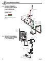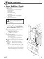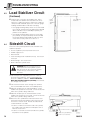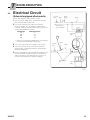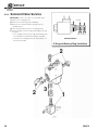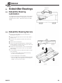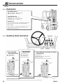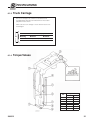
1
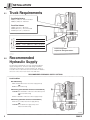
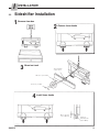
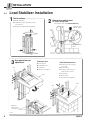
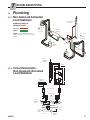
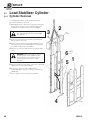
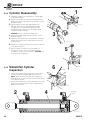
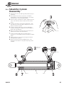
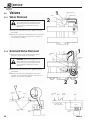
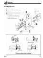
S ERVICE MANUAL E-Series Load Stabilizer Manual Number 204312 cascade corporation Cascade is a Registered Trademark of Cascade Corporation C ONTENTS INTRODUCTION, Section 1 Special Definitions INSTALLATION, Section 2 Truck Requirements Recommended Hydraulic Supply Sideshifter Installation Load Stabilizer Installation Prior to Operation PERIODIC MAINTENANCE, Section 3 TROUBLESHOOTING, Section 4 General Procedures Plumbing Hosing Diagrams Circuit Schematics Troubleshooting Load Stabilizer Circuit Sideshift Circuit Electrical Circuit SERVICE, Section 5 Attachment Removal Load Stabilizer Removal Sideshifter Removal Arm Assembly Arm Assembly Removal Arm Service Load Stabilizer Cylinder Cylinder Removal Cylinder Disassembly Cylinder Inspection Cylinder Reassembly Sideshifter Cylinder Cylinder Removal Cylinder Disassembly Cylinder Inspection Cylinder Reassembly Valve Valve Removal Solenoid Valve Removal Valve Service Solenoid Valve Service Sideshifter Bearings Bearing Lubrication Bearing Service SPECIFICATIONS, Section 6 Hydraulics Auxiliary Valve Functions Truck Carriage Torque Values i Page 1 1 2 2 2 3 4 8 9 10 10 11 11-12 11-12 13 13 14 15 16 16 16 16 18 18 19 20 20 21 21 22 23 23 24 24 25 26 26 26 27 28 29 29 29 30 30 30 31 31 204312 I NTRODUCTION This manual provides the installation instructions, periodic maintenance requirements, troubleshooting procedures and service guides for E-Load Stabilizers. Note that all specifications are shown in US and (Metric) units where applicable. IMPORTANT: All hardware on E-Series attachments is metric. All hosing and fittings are JIC. 1.1 Special Definitions WARNING A statement preceded by WARNING is information that should be acted upon to prevent bodily injury. A WARNING is always inside a ruled box. CAUTION - A statement preceded by CAUTION is information that should be acted upon to prevent machine damage. IMPORTANT - A statement preceded by IMPORTANT is information that possesses special significance. NOTE - A statement preceded by NOTE is information that is handy to know and may make your job easier. 204312 1 I 2.1 NSTALLATION Truck Requirements Truck Relief Setting 2000 psi (140) bar – Recommended 2300 psi (160) bar – Maximum Truck Flow Volume 5 GPM (19 L/min.) – Minimum 8 GPM (30 L/min.) – Recommended 10 GPM (37 L/min.) – Maximum Dimension A − ITA (ISO) Mounting Minimum Maximum Class II 14.96 in. (380.0 mm) 15.00 in. (381.0 mm) Class III 18.68 in. (474.5 mm) 18.74 in. (476.0 mm) Clean carriage bars. Inspect for damaged notches. 2.2 Recommended Hydraulic Supply The attachment will require one of the following hydraulic supply arrangements. All hoses and fittings should be at least No. 6 with 9/32 in. (7 mm) minimum I.D. Refer to Cascade Hose & Cable Reel Selection Guide Form 4099 to select the correct hose reels for the mast and truck. RECOMMENDED HYDRAULIC SUPPLY OPTIONS Load Stabilizer Non-Sideshifting A RH THINLINETM 2-Port Hose Reel Supply Group OR B Mast Internal Reeving Sideshifting (Non-Solenoid Activated Load Stabilizer) A and B RH THINLINETM 2-Port Hose Reel Group and Mast Internal Reeving OR A RH THINLINETM 4-Port Hose Reel Supply Group Sideshifting (Solenoid Activated Load Stabilizer) A RH 6-N-1 Cable/Hose Reel Supply Group OR A and B RH Cable Reel Supply Group and Mast Internal Reeving 2 204312 I 2.3 NSTALLATION Sideshifter Installation 1 Remove from box 2 3 Remove lower hooks Mount on truck Truck carriage center notch .60–.66 in. (15-17 Nm) .32–.36 in. (7-9 Nm) 4 Install lower hooks .06 in. (1.5 mm) .13 in. (3.0 mm) 204312 Tighten to 115-125 ft.-lbs. (155-170 Nm) 3 I 2.4 NSTALLATION Load Stabilizer Installation 1 Attach overhead hoist 3 1000 lbs. 450 kg 2 Remove lower hooks Mount on truck 4 Install lower hooks 140-150 ft.-lbs. (190-200 Nm) Center on Carriage Truck carriage center notch 18-20 ft.-lbs. (20-30 Nm) Hook 4 With the hook front capscrews finger tight, tighten the side capscrew first. 204312 I NSTALLATION 5 Install solenoid valve – Solenoid equipped units. Cable assembly not shown Button toward driver .25 in. (6 mm) Adapter Truck control valve handle 6 7 Install solenoid control knob – Solenoid equipped units. Install wiring – Solenoid equipped units. 7.5 Amp Fuse White Knob Button Black 18 Gauge wire 1/4 in. Terminals 8 Show correct knob cover side Coils Solenoid Valve Two Function 7.5 Amp Fuse White Black User supplied wire 204312 Solenoid Valve 5 I 2.4 NSTALLATION Load Stabilizer Installation 9 Internal reeving hydraulic supply Hose reel hydraulic supply Flush hydraulic supply hoses A Install hoses B Operate auxiliary valves (both directions) C Remove hoses 10 Stabilizer Down Stabilizer Up Install hoses LOAD STABILIZER NON-SIDESHIFTING Using Installation Kit 202127 Stabilizer Down LOAD STABILIZER SIDESHIFTING Stabilizer Up SSR SSL Using Installation Kit 202126 Stabilizer Down LOAD STABILIZER – SOLENOID ACTIVATED SIDESHIFTING Using Installation Kits 202126 and 202127 Allow length for 4 in. sideshift in each direction Allow length for 4 in. sideshift in each direction Stabilizer Up SSR SSL 6 204312 I NSTALLATION 11 Auxiliary valve functions Tilt forward Lift down Lift up LOAD STABILIZER NON SIDESHIFTING A Stabilizer Up B Stabilizer Down 204312 LOAD STABILIZER SIDESHIFTING A B C D Sideshift Left Sideshift Right Stabilizer Up Stabilizer Down Tilt back LOAD STABILIZER – SOLENOID ACTIVATED SIDESHIFTING A A B B Sideshift Left Stabilizer Up (press knob button) Sideshift Right Stabilizer Down (press knob button) 7 I 2.4 NSTALLATION Load Stabilizer Installation 1 Test functions 2 A Raise Stabilizer B Hold truck valve open 10 seconds to remove air C Repeat for sideshift (if equipped) Clamp force adjustment To reduce clamp force – Turn internal setscrew counterclockwise Remove plug Adjust -10% Non-Adjustable Relief 3 Arm operation and adjustment Pin Fold-down Arm A B C D Quick-disconnect Arm Pull out pins Fold down arm Install pins Reverse for fold-up A Position the arm resting on a stack. B Pull out pins C Actuate control valve to lower the arm carrier. D Install pins E Back away F Reverse for installation Arm Arm Pin Adjust to take up arm movement 8 204312 P 3.1 ERIODIC MAINTENANCE 100 Hour Maintenance Every time the lift truck is serviced or every 100 hours of truck operation, whichever comes first, complete the following maintenance procedures: IMPORTANT: After completing any service procedure, test each function through 5 complete cycles. First test the attachment empty, then test each function with a load to make sure the attachment operates correctly before returning it to the job. • Inspect the load stabilizer lower hooks. Tighten the side capscrew to a torque of 18-20 ft.-lbs. (25-27 Nm). Tighten the hook capscrews to a torque of 140-150 ft.-lbs. (190-200 Nm). See Section 5.1 step 5. • Inspect the clearance between the truck lower carriage bar and the sideshifter (if equipped). Retighten the lower hook capscrews. See Section 2.3 step 4. 3.2 500 Hour Maintenance After 500 hours of lift truck operation, in addition to the 100 hour maintenance, perform the following procedures: • Apply chassis grease to the sideshifter (if equipped), upper bearing zerk fitting and lower bearings. See Section 5.6-1. Apply chassis grease to the load stabilizer arm bars. See Section 5.2-1 step 4. 3.3 1000 Hour Maintenance After 1000 hours of lift truck operation, in addition to the 100 and 500 hour maintenance procedures, perform the following procedures: • Inspect the thickness of the sideshifter upper bearings. If either of the bearings are worn to less than 1/16 in. (1.5 mm) thick on the back surface, see Section 5.6-2 for replacement. • Inspect the exposed thickness of the sideshifter lower bearings. If the exposed thickness is worn to less than 1/16 in. (1.5 mm) on the back surface, see Section 5.6-2 for replacement. • Inspect the exposed thickness of the arm bar bearings. If the exposed thickness is worn to less than 1/8 in. (3 mm), see Section 5.2-1 for replacement. 3.4 2000 Hour Maintenance After each 2000 hours of lift truck operation, in addition to the 100, 500 and 1000 hour maintenance, perform the following procedures: • Replace the sideshifter upper and lower bearing sets. Section 5.6-2. • Replace the load stabilizer arm bearings. Section 5.2-1. 204312 9 T ROUBLESHOOTING General Procedures 4.1 WARNING: Before servicing any hydraulic component, relieve pressure in the system. Turn the truck off, then actuate the truck auxiliary control valve(s) several times in both directions. After completing any service procedure, always test the function through several cycles. First test the attachment empty to bleed any air trapped in the system to the truck tank. Then test the attachment with a load to be sure it operates correctly before returning to the job. Stay clear of the load while testing. Do not raise the load more than 3 in. (75 mm) off the floor while testing. Truck System Requirements 4.1-1 • The lift truck must supply sufficient hydraulic pressure to handle the heaviest load, PRESSURE TO THE ATTACHMENT MUST NOT EXCEED 2300 psi (160 bar). • Hydraulic flow should be within volume range shown. • The truck hydraulic system must supply hydraulic oil to the attachment that meets the specifications shown. 4.1-2 Tools Required (Metric) In addition to a normal selection of metric hand tools you will need: Truck Relief Setting 2000 psi (140 bar) – Recommended 2300 psi (160 bar) – Maximum Truck Flow Volume 3 GPM (11 L/min) – Minimum 8 GPM (30 L/min) – Recommended 10 GPM (37 L/min) – Maximum Hydraulic Oil Cascade attachments are compatible with SAE 10W petroleum base hydraulic fluid per Mil. Spec. MIL-0-5606 or MIL-0-2104B. Use of synthetic or aqueous base hydraulic fluid is not recommended. Contact Cascade if fire resistant hydraulic oil must be used. • A pressure gauge capable of measuring pressure to 2500 psi (175 bar), Cascade part no. 671212. • An inline flow meter capable of measuring hydraulic flow to 20 GPM (80 L/min), Cascade Part No. 671477. 4.1-3 Get All The Facts It is important that you gather all the facts regarding the problem before you begin service procedures. The best way is to talk to the operator. Ask for a complete description of the malfunction. The following guidelines will help you decide where to begin your troubleshooting procedures. • Arm will not move, • Arm moves slowly. Normal speed is 4 in. (100 mm) per second. Flow Meter Kit 671477 (2)No. 8-12 JIC/ O-Ring Flow Meter GA0013.eps (2) No. 6-8 JIC Reducer Pressure Gauge Kit 671212 Pressure Gauge No. 6-6 Hose No. 6 and No. 8 JIC Swivel Tee For help with one of these problems, see Section 4.3. • Arm will not sideshift, • Attachment sideshifts slowly. For help with one of these problems, see Section 4.4. GA0014.eps No. 4-6 Pipe/JIC No. 6-8 JIC Reducer No. 4, No. 6 * and No. 8 JIC/O-Ring * Not included in Pressure Gauge Kit part no. 671212. 10 204312 T ROUBLESHOOTING 4.2 Plumbing 4.2-1 Non-Solenoid Activated Load Stabilizer Load Stabilizer Cylinder STABILIZE LOAD and SIDESHIFT RIGHT Hose Reel OR Internal Reeving Pressure: Return: Sideshift Cylinder NOTE: For RELEASE LOAD and SIDESHIFT LEFT, reverse the colors shown. Hose Reel OR Internal Reeving Truck Auxiliary Valves Valve Hose Terminal Load Stabilizer Cylinder Valve 4.2-2 Circuit Schematic– Non-Solenoid Activated Load Stabilizer Sideshift Cylinder Hose Terminals Hose Reels OR Internal Reeving Truck Auxiliary Valves Truck Tank Truck Relief Valve LP0163.eps 204312 Truck Hydraulic Pump 11 T 4.2-3 ROUBLESHOOTING Hosing Diagram– Solenoid Activated Load Stabilizer Load Stabilizer Cylinder STABILIZE LOAD and SIDESHIFT RIGHT Pressure: Return: Sideshift Cylinder NOTE: For RELEASE LOAD and SIDESHIFT LEFT, reverse the shades shown. Solenoid Valve Valve 6-N-1 Internal Cable Reeving Hose OR and Reel Cable Reel Hose Terminal Load Stabilizer Cylinder 4.2-4 Valve Circuit Schematic– Solenoid Activated Load Stabilizer Sideshift Cylinder 6-N-1 Internal Cable Reeving Hose OR and Reel Cable Reel Truck Relief Valve 12 Truck Tank LS0164.eps Truck Hydraulic Pump 204312 T 4.3 ROUBLESHOOTING Load Stabilizer Circuit There are seven potential problems that could affect the stabilizer operation: • Incorrect hydraulic pressure/volume from truck. • Kinked supply hoses. • External leaks. • Physically jammed arm. • Faulty electrical connection (solenoid equipped attachments). • Defective solenoid valves (solenoid equipped attachments). • Valve assembly malfunction. WARNING: Before removing any hoses, relieve pressure in the hydraulic system. With the truck off, open the truck auxiliary control valve(s) several times in both directions. 1 Check the pressure supplied by the truck. Refer to the truck Service Manual. The recommended truck pressure is 2000 psi (140 bar). TRUCK PRESSURE MUST NOT EXCEED 2300 PSI (160 BAR), measured at the carriage hose terminal. 2 Check the flow volume at the carriage hose terminal. The recommended flow volume is: 5 GPM (19 L/min) – Minimum 8 GPM (30 L/min) – Recommended 10 GPM (37 L/min) – Maximum 3 Solenoid Valve equipped attachments – Press the control knob clamp button. • If the solenoid valve “clicks”, it is working correctly. Continue troubleshooting. • If the solenoid does not “click”, test the electrical circuit as described in Section 4.5. 4 Install a pressure gauge to the cylinder rod end test tee fitting. 4 5 Start the truck. Retract the cylinder and build up pressure as in clamping on a load. Note the gauge reading. • If the gauge reading is 1800 ± 25 psi (124 ± 1.8 bar), continue troubleshooting. • If the gauge reading is above or below1800 ± 25 psi (124 ± 1.8 bar), adjust the clamp relief cartridge. Refer to Section 5.5 step 2. Turn the internal setscrew clockwise to increase pressure, or counterclockwise to decrease pressure. 204312 13 T 4.3 ROUBLESHOOTING Load Stabilizer Circuit (Continued) 6 Start the truck. Fully raise the stabilizer arm. Place a load under the stabilizer arm that allows the arm to retract 6 in. (150 mm) minimum. Retract the cylinder to clamp the load and build up pressure. Note the gauge readings at 30 and 90 seconds after clamping. Fully raised stabilizer arm 6 in. (150 mm) maximum • If the gauge reading initially shows no less than 1650 psi (114 bar), and the pressure drop between 30 and 90 seconds does not exceed 500 psi (35 bar), the problem is not hydraulic. Load • If the gauge reading initially shows less than 1650 psi (114 bar), or the pressure drops more than 500 psi (35 bar) between 30 and 90 seconds, the valve check valve is faulty. Refer to Section 5.5-1. 4.4 Sideshift Circuit There are seven potential problems that could affect the stabilizer operation: • Incorrect hydraulic pressure/volume from truck. • Kinked supply hoses. • External leaks. • Lower mounting hooks installed incorrectly. See Section 2.3 step 4. • Worn bearings. See Section 5.6-2. • Worn or defective cylinder seals. WARNING: Before removing any hoses, relieve pressure in the hydraulic system. With the truck off, open the truck auxiliary control valve(s) several times in both directions. 1 Check the pressure supplied by the truck. Refer to the truck Service Manual. The recommended truck pressure is 2000 psi (140 bar). TRUCK PRESSURE MUST NOT EXCEED 3000 PSI (207 BAR), measured at the carriage hose terminal. 2 Check the flow volume at the carriage hose terminal. The recommended flow volume is 2.5 GPM (9 L/min). 3 Sideshift completely to the right and hold the control 1 Cap supply fitting handle in this position for 5 seconds. Check for external leaks at the cylinder, fittings and hoses. Sideshift RIGHT Hose Hose end in drain bucket 2 Front View 4 Sideshift completely to the left and hold the control handle in this position for 5 seconds. Check for external leaks at the cylinder, fittings and hoses. 5 Disconnect the cylinder base end hose from the hose terminal or internal reeving fitting. Place the hose end in a bucket. Start the truck. Actuate the sideshift left control handle for 5 seconds. • If there is oil flow out of the base end of the cylinder, the cylinder seals are defective and require service. Refer to Section 5.4-2. • If there is no oil flow out of the rod end of the cylinder, the problem is not hydraulic. 14 5 Place the cylinder base end hose in a bucket. 204312 T 4.6 ROUBLESHOOTING Electrical Circuit (Solenoid equipped attachments) See the wire diagrams and schematic shown. 7.5 Amp Fuse White Knob Button Black 1 Check for truck voltage at the solenoid coil terminals when the knob button is pressed. 2 Check the solenoid coil to make sure it matches the truck voltage. The coil voltage is marked at the terminals. Verify by checking the resistance across the terminal with wired disconnected. Coil Voltage 12V 24V 36V 48V 18 Gauge wire 1/4 in. Terminals Coils Ohms Resistance 2 14 36 44 Solenoid Valve • If there is no ohmmeter reading shown, the solenoid coil is defective and requires replacing. 3 Check the control knob fuse. Replace if necessary. 4 Check for loose electrical connections at the truck 7.5 Amp Fuse White Black ignition switch, control knob button(s), solenoid valve terminals and diodes. 5 Remove the diode from the solenoid valve terminal. Test with an ohmmeter for high resistance in one direction and no resistance in the other direction. If there is no resistance in both directions, replace the diode. User supplied wire 204312 Solenoid Valve 15 S 5.1 ERVICE Attachment Removal 1 Load Stabilizer Removal 5.1-1 WARNING: Make sure the overhead hoist has a rated lifting capacity of at least 1000 lbs. (450 kg). 1 Attach an overhead hoist to the center frame crossmember. Take up slack in the chain. WARNING: Before removing any hoses, relieve pressure in the hydraulic system. Turn the truck off, then actuate the truck control valve(s) several times in both directions. 2 Disconnect hoses from the valve and sideshift cylinder (if equipped). Tag the hoses for reassembly. 3 Remove the lower hook capscrews fastening the load stabilizer to the sideshifter or truck carriage. 4 Lift away the load stabilizer. 5 For installation, reverse the above procedures except as Stabilizer Down Stabilizer Up follows: • Install the lower mounting hook capscrews (finger tight) and the side capscrew. Tighten the side capscrew, into the nut, to a torque of 18-20 ft.-lbs. (25-30 Nm). Tighten the lower hook capscrews to a torque of 140-150 ft.-lbs. (190-200 Nm). 2 3 140-150 ft.-lbs. (190-200 Nm) 18-20 ft.-lbs. (25-30 Nm) Hook 5 16 With the hook front capscrews finger tight, tighten the side capscrew first. 204312 S 5.1-2 ERVICE Sideshifter Removal 1 Remove the forks from the sideshifter. WARNING: Before removing any hoses, relieve pressure in the hydraulic system. Turn the truck off, then actuate the truck control valve(s) several times in both directions. 2 Disconnect the hoses from the cylinder. If wrench clearance is limited, remove the cylinder for better access. Tag the hoses for reassembly. 2 3 3 Remove the lower mounting capscrews. 4 4 Attach a 1000 lbs. (450 kg) capacity overhead hoist. Remove the sideshifter from the truck. 5 For installation, reverse the above procedures except for the following special instructions for the lower mounting hooks: • Install the lower mounting hooks tight against the carriage bar then back off one rib position. The clearance between the hooks and carriage bar must be .06 in. (1.5 mm) minimum to .125 in. (3.0 mm) maximum. Tighten the capscrews to a torque of 115-125 ft.-lbs. (155-169 Nm). Truck Carriage Bar 1/16 in. (1.5 mm) 1/8 in. (3 mm) 5 204312 17 S 5.2 ERVICE Arm Assembly Arm Assembly Removal 5.2-1 2 The following procedures can be performed with the attachment mounted on the truck. 1 WARNING: Make sure the overhead hoist has a rated lifting capacity of at least 1000 lbs. (450 kg). 1 Attach an overhead hoist to the arm carrier/arm base. Take up slack in the chain. Arm Carrier 3 2 Remove the capscrews fastening the cylinder clevis to the arm carrier. 3 Remove the arm assembly though the top of the frame. 4 For reassembly, reverse the above procedures except as follows: • Tighten the cylinder clevis capscrews to a torque of 48-52 ft.-lbs. (65-70 Nm). • Inspect the arm bar bearings for wear. If the bearing contact surfaces are worn to less than .125 in. (3 mm) they should be replaced. 4 Arm Bar Bearings • Lubricate the full length of the bearings and arm bars with chassis grease during reassembly. Cylinder Clevis 18 204312 S ERVICE Arm Service Shim 5.2-2 Carrier The following procedures can be performed with the attachment mounted on the truck. 1 Remove the arm assembly from the attachment as Arm described in Section 5.2-1. 2 Perform one or all of the following procedures as needed. Arm Bar Service – Remove the capscrews fastening the arm bar to the carrier. For reassembly, tighten the capscrews to a torque of 48-52 ft.-lbs. (65-70 Nm). Arm Bars Rubber Washer Contact Pad Service – Remove the nuts and capscrews fastening the contact pad to the arm. If only the front portion of the contact pad is worn, rotate it 180° and reinstall. For reassembly, tighten the nuts under the rubber washers to a torque of 48-52 ft.-lbs. (65-70 Nm). Tighten the castellated nuts to allow flexibility and install the cotter pins. Contact Pad Quick-Disconnect Arm Shim Top Plate Arm Bar Rubber Washer Arm Bars Bottom Plate Contact Pad Bottled Water Arm 204312 19 S 5.3 ERVICE Load Stabilizer Cylinder Cylinder Removal 5.3-1 The following procedures can be performed with the attachment mounted on the truck. 1 Bottled Water Units – Remove the capscrews fastening the bumper to the frame. For reassembly, tighten the capscrews to a torque of 48-52 ft.-lbs. (65-70 Nm). WARNING: Make sure the overhead hoist has a rated lifting capacity of at least 1000 lbs. (450 kg). 2 3 Arm Carrier 2 Attach an overhead hoist to the arm carrier/arm base. Take up slack in the chain. 3 Remove the capscrews fastening the cylinder clevis to the arm carrier. For reassembly, tighten the capscrews to a torque of 48-52 ft.-lbs. (65-70 Nm). 4 Remove the capscrew and nut from the cylinder base end. 6 WARNING: Before removing any hoses, relieve pressure in the hydraulic system. Turn the truck off, then actuate the truck control valve(s) several times in both directions. Cylinder Clevis 5 5 Pull the cylinder out of the frame. Disconnect, plug and tag the hoses to the cylinder fittings. 1 6 Remove the clevis from the cylinder rod. For reassembly, tighten the nut to a torque of 22-29 ft.-lbs. (30-40 Nm). 7 For installation, reverse the above procedures. 4 20 204312 S 5.3-2 ERVICE Load Stabilizer Cylinder Disassembly 1 Clamp the cylinder in a soft-jawed vise. the extreme base end only. Claw type spanner wrench Clamp lightly at 2 Remove the retainer by using a claw type spanner wrench part no. 678598. 3 Remove the rod assembly from the cylinder. illustration below. 4 Clamp the rod assembly at the rod end. directly on the rod sealing surface. See the Never clamp 1 5 Remove the nut fastening the piston to the rod. Use a strap wrench to keep the rod from rotating while removing the nut. 6 Place the piston or retainer in a soft-jawed vise to remove the seals. Pry the seals up with a blunt screwdriver. Cut the seal to remove it. CAUTION: Do not scratch the seal grooves. 5.3-3 4 Load Stabilizer Cylinder Inspection • Inspect all components for nicks or burrs. Minor nicks and burrs can be removed with 400 grit emery cloth. NOTE: Minor nicks are those that will not bypass oil under pressure. If they cannot be removed with emery cloth, replace the part. • Inspect the outside of the shell for deformities that could weaken the shell's performance when under pressure. Replace if necessary, 6 5 Remove seal from piston. Do not scratch the groove. 3 204312 5 2 21 S 5.3-4 ERVICE 3 Load Stabilizer Cylinder Reassembly 1 Lubricate all new seals and rings with petroleum jelly or equivalent. 2 Note the direction of the U-cup seals. 4 If installed backwards the seals will not work properly. For proper seal placement, see illustration below. 3 Polish the piston and retainer chamfer angle with emery cloth. This allows the seal to slide over the chamfer easier. 6 4 Install the new seals on the piston and retainer. Hook one side of the seal in the groove and push it over the piston on retainer as shown. Install new seals. Do not allow lower edge of loader to contact thread relief chamfer. 5 Install the piston on the rod and tighten the piston retaining nut to a torque of 43-47 ft.-lbs. (58-64 Nm). 6 Place the piston loader in the cylinder shell. The loader must cover all of the threads but not contact the thread relief chamfer. The length of the stop fins can be trimmed with a sharp knife if more engagement is needed. The piston will not enter the shell if the loader contacts the thread relief chamfer. Stop Fins Cylinder Shell 7 Apply a thick film of petroleum jelly to the inside of the cylinder shell, piston loader and piston seals. 8 Insert the rod-piston assembly through the loader into the Piston Loader cylinder shell. If resistance is encountered, tap the rod end with a rubber mallet. 9 Remove the loader from the shell. scratch the cylinder bore. 10 CAUTION: Do not 8 Install the retainer over the rod, then into the shell. Tighten the retainer to a torque of 60-70 ft.-lbs. (81-95 Nm). 7 5 22 10 Piston Rod Shell Retainer 204312 S 5.4 ERVICE Sideshifter Cylinder Sideshifter Cylinder Removal 5.4-1 1 Remove the load stabilizer from the sideshifter as described in Section 5.1. 2 Position the forks to access the cylinder. 4 WARNING: Before removing any hoses, relieve pressure in the hydraulic system. Turn the truck off, then actuate the truck control valve(s) several times in both directions. 3 Disconnect the hydraulic lines from the cylinder ports. Plug the lines and cap the cylinder ports. 4 Remove the cotter pin and clevis pin from the cylinder ends. 5 For reassembly, reverse the above procedures except for the following: • Operate the sideshifter through several full cycles to force air in the system to the truck hydraulic tank. Check for leaks at all fittings. 204312 3 23 S 5.4-2 ERVICE 1 Cylinder Disassembly 1 Clamp the cylinder in a soft-jawed vise. on the base end only. Clamp lightly 2 Position the cylinder rod in the fully extended position. Remove the spiral snap rings from the retainer. See the illustration below. 3 Tap the retainer into the shell approximately 2 in. (50 mm). Remove the retaining ring by placing a screwdriver on one side of the ring near the split and tapping with a hammer. The retaining ring will compress and turn sideways. CAUTION: Do not scratch the cylinder bore. 4 Remove the rod assembly from the cylinder. illustration below. SS0059.eps 3 See the 5 Clamp the rod assembly in a soft-jawed vise or between two blocks of wood. Never clamp directly on the rod sealing surface. 6 Remove the nut fastening the piston to the rod. the piston and retainer. SS0089.eps Remove 5 7 Place the piston or retainer in the soft-jawed vise to remove the seals. Pry the seals up with a blunt screwdriver. Cut the seals to remove it. CAUTION: Do not scratch the seal grooves. 5.4-3 6 Sideshifter Cylinder Inspection SS0255.eps • Inspect all components for nicks or burrs. Minor nicks or burrs can be removed with 400 grit emery cloth. NOTE: Minor nicks are those that will not bypass oil under pressure. If nicks cannot be removed with emery cloth, replace the part. • Inspect the outside of the shell for deformities that could weaken the shell’s performance when under pressure. Replace if necessary. 2 SS0088.eps 4 Restrictor Washer SS0057.eps 24 204312 S 5.4-4 ERVICE Sideshifter Cylinder Reassembly 1 Lubricate all new seals and rings with petroleum jelly or equivalent. 3 2 Note the direction of the U-cup seals. If installed backwards the seals will not work properly. For proper seal placement, see the illustration below. 3 Polish the piston and retainer chamfer angle with emery cloth. This allows the seals to slide over the chamfer easier. 4 Install the new seals on the piston and retainer. Hook one side of the seal in the groove and push it over the piston or retainer as shown. 5 Install the retainer and piston on the rod and tighten the piston retaining nut. Tighten the nut to a torque of 70-75 ft.-lbs. (95-102 Nm). 6 Apply a thick film of petroleum jelly to the inside of the SS0063.eps cylinder shell, piston seals and retainers. 7 Insert the rod assembly into the cylinder shell. If resistance is encountered, tap the rod end with a rubber mallet. 8 Tap the retainer into the shell far enough to install the retaining ring in its groove. 9 Pull the rod out to the fully extended position. This will position the retainer so the spiral snap ring can be installed. 2 Note seal direction OR SS0256.eps 9 SS0084.eps 8 7 204312 Retainer Shell Piston 5 25 S 5.5 ERVICE 1 Valves Valve Removal 5.5-1 WARNING: Before removing any hoses, relieve pressure in the hydraulic system. Turn the truck off, then actuate the truck control valve(s) several times in both directions. 1 Remove the hoses from the valve. reassembly. 2 Valve Stabilizer Down Stabilizer Up Tag the hoses for 2 Remove the capscrews fastening the valve to the frame. For reassembly, tighten the capscrews to a torque of 12-14 ft.-lbs. (17-19 Nm). 1 Solenoid Valve Removal 5.5-2 1 Remove the wires connected to the solenoid coil terminals. Tag the wires for reassembly. WARNING: Before removing any hoses, relieve pressure in the hydraulic system. Turn the truck off, then actuate the truck control valve(s) several times in both directions. 2 Remove the hoses from the valve. reassembly. Stabilizer Up Stabilizer Down SS Right SS Left Tag the hoses for 2 Remove the capscrews fastening the valve to the carriage. For reassembly, tighten the capscrews to a torque of 12-14 ft.-lbs. (17-19 Nm). 2 7.5 Amp Fuse 3 White Black 7.5 Amp Fuse White Knob Button Black 18 Gauge wire 1/4 in. Terminals User supplied wire 26 Solenoid Valve Coils Solenoid Valve 204312 S 5.5-3 ERVICE Valve Service IMPORTANT: Service the valve in a clean work area. 1 Remove the cartridge valves. 2 Remove the remaining plugs and fittings. 3 Remove the O-rings and back-up rings from the cartridge valves. 4 Clean all parts with kerosene or cleaning solvent. 5 For reassembly, reverse the above procedures 1 2 Relief ValveAdjustable except as follows: • The cartridge valve back-up rings and O-rings must be installed as shown below for proper operation. • Lubricate the cartridge and seals with hydraulic oil prior to reassembly. 1 3 Relief ValveFixed 3 Flow Regulator Check Valve 2 O-Rings O-Rings Back-up Rings Check Valve Back-up Ring Relief Valve-Fixed O-Rings O-Rings Back-up Ring Back-up Ring Relief Valve-Adjustable Flow Regulator O-Ring and Back-up Ring Installation 204312 27 S 5.5-4 ERVICE Solenoid Valve Service IMPORTANT: Service the valve in a clean work area. 1 Remove the cartridge valves. 2 Remove the remaining plugs and fittings. 3 Remove the O-rings and back-up rings from the O-Rings cartridge valves. 4 Clean all parts with kerosene or cleaning solvent. 5 For reassembly, reverse the above procedures except as follows: • The cartridge valve back-up rings and O-rings must be installed as shown below for proper operation. Back-up Ring • Lubricate the cartridge and seals with hydraulic oil prior to reassembly. Solenoid Valves O-Ring and Back-up Ring Installation 2 2 3 1 Solenoid Cartridge Valve 28 204312 S ERVICE 5.6 Sideshifter Bearings 5.6-1 Sideshifter Bearing Lubrication Lubrication Points The sideshifter will require lubrication with chassis grease every 500 hours of operation. Apply grease at the zerk fitting lube points shown. Sideshift to expose the upper fittings. 5.6-2 Sideshifter Bearing Service 1 Remove the load stabilizer from the sideshifter as described in Section 5.1. 2 Remove the sideshifter from the truck as described in Section 5.1-2. 3 Disconnect the cylinder anchor pin from the anchor bracket. 4 Remove the anchor bracket. 5 Remove the upper bearing segments. Replace both bearing segments if either one is worn to less than 1/16 in. (1.5 mm) thick on the back side. 6 Measure the exposed thickness of the lower bearings. If the thickness is less than 1/16 in. (1.5 mm), replace both bearings. 5 7 For reassembly, reverse the above procedures except Anchor Bracket 4 for the following: • Clean the frame upper hook and lower bearing pockets of any built-up grease. • Clean all parts prior to reassembly. • After the sideshifter is reassembled and mounted on the truck, apply chassis grease to the bearing zerk fittings. See Section 5.6-1 above. 204312 3 6 29 S PECIFICATIONS Hydraulics 6.1-1 Truck Relief Setting 2000 psi (140) bar – Recommended 2300 psi (160) bar – Maximum Truck Flow Volume 5 GPM (19 L/min.) – Minimum 8 GPM (30 L/min.) – Recommended 10 GPM (37 L/min.) – Maximum Hydraulic Oil Cascade attachments are compatible with SAE 10W petroleum base oil per Mil. Spec. MIL-0-5606 or MIL-0-2104B. Use of synthetic or aqueous base hydraulic oil is not recommended. Contact Cascade if fire resistant hydraulic oil must be used. Auxiliary Valve Functions 6.1-1 Tilt forward Lift down Lift up LOAD STABILIZER NON SIDESHIFTING A Stabilizer Up B Stabilizer Down LOAD STABILIZER SIDESHIFTING A B C D Sideshift Left Sideshift Right Stabilizer Up Stabilizer Down Tilt back LOAD STABILIZER–SOLENOID ACTIVATED SIDESHIFTING A A B B Sideshift Left Stabilizer Up (press knob button) Sideshift Right Stabilizer Down (press knob button) Operate Attachment Functions If functions are backward – switch hoses at hose terminal, hose reel or auxiliary valve. 30 204312 S 6.1-3 PECIFICATIONS Truck Carriage The truck carriage must conform to ISO dimensional standard 2328, equivalent to Industrial Truck Association (ITA) dimensions shown. Make sure the truck carriage is clean and the notches are undamaged. Dimension A − ITA (ISO) A Mounting Class II Minimum Maximum 14.96 in. (380.0 mm) 15.00 in. (381.0 mm) GA0028.eps 6.1-4 Torque Values Ref. No. 1 2 3 4 5 6 7 204312 Torque Values Ft.-lbs. 48-52 33-37 6-7 12-14 22-30 18-20 140-150 (Nm) 65-70 45-50 8-10 17-19 30-40 25-30 190-200 31 Do you have questions you need answered right now? Call your nearest Cascade Service Department. Visit us online at www.cascorp.com AMERICAS Cascade Corporation U.S. Headquarters 2201 NE 201st Fairview, OR 97024-9718 Tel: 800-CASCADE (227-2233) Fax: 888-329-8207 Cascade do Brasil Rua João Guerra, 134 Macuco, Santos - SP Brasil 11015-130 Tel: 55-13-2105-8800 Fax: 55-13-2105-8899 Cascade Canada Inc. 5570 Timberlea Blvd. Mississauga, Ontario Canada L4W-4M6 Tel: 905-629-7777 Fax: 905-629-7785 EUROPE-AFRICA Cascade Italia S.R.L. European Headquarters Via Dell’Artigianato 1 37050 Vago di Lavagno (VR) Italy Tel: 39-045-8989111 Fax: 39-045-8989160 Cascade (Africa) Pty. Ltd. PO Box 625, Isando 1600 60A Steel Road Sparton, Kempton Park South Africa Tel: 27-11-975-9240 Fax: 27-11-394-1147 ASIA-PACIFIC Cascade Japan Ltd. 2-23, 2-Chome, Kukuchi Nishimachi Amagasaki, Hyogo Japan, 661-0978 Tel: 81-6-6420-9771 Fax: 81-6-6420-9777 Cascade Korea 121B 9L Namdong Ind. Complex, 691-8 Gojan-Dong Namdong-Ku Inchon, Korea Tel: +82-32-821-2051 Fax: +82-32-821-2055 Cascade-Xiamen No. 668 Yangguang Rd. Xinyang Industrial Zone Haicang, Xiamen City Fujian Province P.R. China 361026 Tel: 86-592-651-2500 Fax: 86-592-651-2571 Cascade Australia Pty. Ltd. 1445 Ipswich Road Rocklea, QLD 4107 Australia Tel: 1-800-227-223 Fax: +61 7 3373-7333 Cascade New Zealand 15 Ra Ora Drive East Tamaki, Auckland New Zealand Tel: +64-9-273-9136 Fax: +64-9-273-9137 Sunstream Industries Pte. Ltd. 18 Tuas South Street 5 Singapore 637796 Tel: +65-6795-7555 Fax: +65-6863-1368 Cascade India Material Handling Private Limited No 34, Global Trade Centre 1/1 Rambaugh Colony Lal Bahadur Shastri Road, Navi Peth, Pune 411 030 (Maharashtra) India Phone: +91 020 2432 5490 Fax: +91 020 2433 0881 c Cascade Corporation 2007 4-1992 Part Number 204312