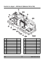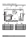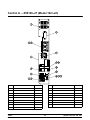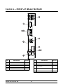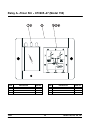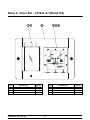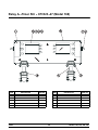
1
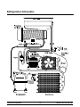
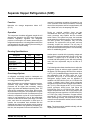
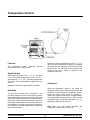
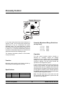
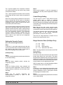
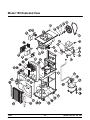
Models 150, 152, 162, 168 Taylormate Freezers Service Manual 028749- S 5/99 Table of Contents Section 1: Introduction . . . . . . . . . . . . . . . . . . . . . . . . . . . . . . . . . . . . . . . . . . . . . . . Safety . . . . . . . . . . . . . . . . . . . . . . . . . . . . . . . . . . . . . . . . . . . . . . . . . . . . . . . . . . . . . Refrigerant . . . . . . . . . . . . . . . . . . . . . . . . . . . . . . . . . . . . . . . . . . . . . . . . . . . . . . . . . Model 150 Specifications . . . . . . . . . . . . . . . . . . . . . . . . . . . . . . . . . . . . . . . . . . . . . Model 152 Specifications . . . . . . . . . . . . . . . . . . . . . . . . . . . . . . . . . . . . . . . . . . . . . Model 162 Specifications . . . . . . . . . . . . . . . . . . . . . . . . . . . . . . . . . . . . . . . . . . . . . Model 168 Specifications . . . . . . . . . . . . . . . . . . . . . . . . . . . . . . . . . . . . . . . . . . . . . Running Specifications . . . . . . . . . . . . . . . . . . . . . . . . . . . . . . . . . . . . . . . . . . . . . . . Installation Instructions . . . . . . . . . . . . . . . . . . . . . . . . . . . . . . . . . . . . . . . . . . . . . . . 1 2 2 4 5 6 7 8 9 Section 2: Controls and Systems . . . . . . . . . . . . . . . . . . . . . . . . . . . . . . . . . . . . . . Refrigeration Schematic . . . . . . . . . . . . . . . . . . . . . . . . . . . . . . . . . . . . . . . . . . . . . . Separate Hopper Refrigeration (SHR) . . . . . . . . . . . . . . . . . . . . . . . . . . . . . . . . . Temperature Control . . . . . . . . . . . . . . . . . . . . . . . . . . . . . . . . . . . . . . . . . . . . . . . . . Viscosity Control . . . . . . . . . . . . . . . . . . . . . . . . . . . . . . . . . . . . . . . . . . . . . . . . . . . . TQC Control . . . . . . . . . . . . . . . . . . . . . . . . . . . . . . . . . . . . . . . . . . . . . . . . . . . . . . . . 11 12 13 14 16 19 Section 3: Troubleshooting Guide . . . . . . . . . . . . . . . . . . . . . . . . . . . . . . . . . . . . . General Troubleshooting . . . . . . . . . . . . . . . . . . . . . . . . . . . . . . . . . . . . . . . . . . . . . Control Troubleshooting . . . . . . . . . . . . . . . . . . . . . . . . . . . . . . . . . . . . . . . . . . . . . . Watt Control Troubleshooting . . . . . . . . . . . . . . . . . . . . . . . . . . . . . . . . . . . . . . . . . 21 22 25 26 Section 4: Parts . . . . . . . . . . . . . . . . . . . . . . . . . . . . . . . . . . . . . . . . . . . . . . . . . . . . . . Warranty Explanation . . . . . . . . . . . . . . . . . . . . . . . . . . . . . . . . . . . . . . . . . . . . . . . . Model 150 Exploded View . . . . . . . . . . . . . . . . . . . . . . . . . . . . . . . . . . . . . . . . . . . . Model 150 Panel Identification . . . . . . . . . . . . . . . . . . . . . . . . . . . . . . . . . . . . . . . . Model 152 Exploded View . . . . . . . . . . . . . . . . . . . . . . . . . . . . . . . . . . . . . . . . . . . . 27 28 30 32 34 Models 150, 152, 162, 168 Table of Contents Table of Contents - Page 2 Model 152 Panel Identification . . . . . . . . . . . . . . . . . . . . . . . . . . . . . . . . . . . . . . . . Model 162 Exploded View . . . . . . . . . . . . . . . . . . . . . . . . . . . . . . . . . . . . . . . . . . . . Model 162 Panel Identification . . . . . . . . . . . . . . . . . . . . . . . . . . . . . . . . . . . . . . . . Model 168 Exploded View . . . . . . . . . . . . . . . . . . . . . . . . . . . . . . . . . . . . . . . . . . . . Model 168 Panel Identification . . . . . . . . . . . . . . . . . . . . . . . . . . . . . . . . . . . . . . . . Beater & Door A. (Models 150/152) . . . . . . . . . . . . . . . . . . . . . . . . . . . . . . . . . . . . Beater & Door A. (Models 162/168) . . . . . . . . . . . . . . . . . . . . . . . . . . . . . . . . . . . . Control A.--Upper -- X51544--27 (Models 150 & 152) . . . . . . . . . . . . . . . . . . . . . Control A. -- X51543--27 (Model 152) . . . . . . . . . . . . . . . . . . . . . . . . . . . . . . . . . . Control A. -- X50146--27 (Model 162 Left) . . . . . . . . . . . . . . . . . . . . . . . . . . . . . . Control A. -- X50147--27 (Model 162 Right) . . . . . . . . . . . . . . . . . . . . . . . . . . . . . Control A. -- X51730--27 (Models 162 & 168 Front) . . . . . . . . . . . . . . . . . . . . . . Control A. -- X50342--27L (Model 168 Left) . . . . . . . . . . . . . . . . . . . . . . . . . . . . . Control A. -- X50342--27R (Model 168 Right) . . . . . . . . . . . . . . . . . . . . . . . . . . . . Box A.--Cap & Relay -- X50198--27 (Model 150) . . . . . . . . . . . . . . . . . . . . . . . . . Relay A.--Timer Stir -- X51685--27 (Model 150) . . . . . . . . . . . . . . . . . . . . . . . . . . Relay A.--Timer Stir -- X51633--27 (Model 162) . . . . . . . . . . . . . . . . . . . . . . . . . . Relay A.--Timer Stir -- X51323--27 (Model 168) . . . . . . . . . . . . . . . . . . . . . . . . . . Parts List . . . . . . . . . . . . . . . . . . . . . . . . . . . . . . . . . . . . . . . . . . . . . . . . . . . . . . . . . . . Wiring Diagrams . . . . . . . . . . . . . . . . . . . . . . . . . . . . . . . . . . . . . . . . . . . . . . . . . . . . 36 38 40 42 44 46 47 48 49 50 51 52 53 54 55 56 57 58 59 67 Note: Continuing research results in steady improvements; therefore, information in this manual is subject to change without notice. CAUTION: Information in this manual is intended to be used by Taylor Authorized Service Technicians only. E May, 1999 Taylor All rights reserved. 028749--S The word Taylor and the Crown design are registered trademarks in the United States of America and certain other countries. Table of Contents Taylor Company 750 N. Blackhawk Blvd. Rockton, IL 61072 Models 150, 152, 162, 168 Section 1: Introduction Models 150, 152, 162, 168 S Specifications S Running Specifications S Installation Instructions 1 Introduction Safety Refrigerant We at Taylor Company, are committed to manufacturing safe operating and serviceable equipment. The many built-in safety features that are part of all Taylor equipment are aimed at protecting operators and trained service technicians alike. Taylor Company uses R404A refrigerant. This refrigerant is generally considered non-toxic and non-flammable; however, any gas under pressure is potentially hazardous. _________________________________ _________________________________ This manual is intended exclusively for Taylor Company authorized service personnel. NEVER fill any refrigerant cylinder completely with liquid. Filling the cylinder to approximately 80% will allow for normal expansion. Stationary appliances which are not equipped with a power cord and a plug or other device to disconnect the appliance from the power source must have an all--pole disconnecting device with a contact gap of at least 3 mm installed in the external installation. Failure to follow this instruction may result in electrocution. Refrigerant liquid sprayed onto the skin may cause serious damage to tissue. Keep eyes and skin protected. If refrigerant burns should occur, flush immediately with cold water. If burns are severe, apply ice packs and contact a physician immediately. The Taylor Company reminds technicians to be cautious of government laws regarding refrigerant recovery, recycling, and reclaiming systems. If you have any questions regarding these laws, please contact the factory Service Department. These machines must be placed on a level surface. Failure to comply may result in personal injury or equipment damage. DO NOT install the unit in an area where a water jet could be used to clean or rinse the freezer. Failure to follow this instruction may result in serious electrical shock. These machines are designed to operate indoors, under normal ambient temperatures of 70_--75_F (21_--24_C). The machines have successfully performed in high ambient temperatures of 104_F (40_C) at reduced capacities. NOISE LEVEL: Airborne noise emission does not exceed 78 dB(A) when measured at a distance of 1.0 meter from the surface of the machine and at a height of 1.6 meters from the floor. WARNING: R404A refrigerant used in conjunction with polyolester oils is extremely moisture absorbent. When opening a refrigeration system, the maximum time the system is open must not exceed 15 minutes. Cap all open tubing to prevent humid air or water from being absorbed by the oil. 040309 Introduction 2 Models 150, 152, 162, 168 Compressor Warranty Disclaimer The refrigeration compressor(s) on this machine are warranted for the term indicated on the warranty card accompanying this machine. However, due to the Montreal Protocol and the U.S. Clean Air Act Amendments of 1990, many new refrigerants are being tested and developed; thus seeking their way into the service industry. Some of these new refrigerants are being advertised as drop-in replacements for numerous applications. It should be noted that, in the event of ordinary service to this machine’s refrigeration system, only the refrigerant specified on the affixed data label should be used. The unauthorized use of alternate refrigerants will void your compressor warranty. It will be the owners’ responsibility to make this fact known to any technicians they employ. The Taylor Company will continue to monitor the industry and test new alternates as they are being developed. Should a new alternate prove, through our testing, that it would be accepted as a drop-in replacement, then the above disclaimer would become null and void. To find out the current status of an alternate refrigerant as it relates to your compressor, call the local Taylor Distributor or the Taylor Factory. Be prepared to provide the model/serial number of the unit in question. It should be noted, that Taylor does not warrant the refrigerant used in its equipment. For example, if the refrigerant is lost during the course of ordinary service to this machine, Taylor has no obligation to either supply or provide its replacement either at billable or unbillable terms. Taylor does have the obligation to recommend a suitable replacement if the original refrigerant is banned, obsoleted, or no longer available during the five year warranty of the compressor. Models 150, 152, 162, 168 3 Introduction Model 150 Specifications This unit is manufactured in other electrical characteristics. Refer to the Distributor Data Book for availability. (For exact electrical information, always refer to the data label of the unit.) Freezing Cylinder One, 1.5 quart (1.4 liter). Mix Hopper Air Cooled One, 8 quart (7.6 liter). Clearance: 6” (15.2 cm.) around both sides. Install the skirt provided on the right side of the unit and place the back of the unit against a wall to prevent recirculation of warm air. Beater Motor One, 0.5 hp. Refrigeration Unit Dimensions One, approximately 3,000 btu/hr. compressor. Refrigerant: R404A. One, independent SHR compressor, approximately 400 btu/hr. R134a. (BTU’s may vary based on compressor used.) Width: 14-1/16” (35.7 cm.) Depth: 24” (61.0 cm.) Height: 51-1/2” (130.8 cm.) Floor Clearance: 3-11/16” (9.4 cm.) mounted on standard casters. Electrical Total Amps Supplied With 115/60/1 Air 16.0 20 amp. cord and plug 208-230/60/1 Air 10.2 15 amp. cord and plug Electrical Introduction Approximate Weights Net: 250 lbs. (113.4 kgs.) Crated: 310 lbs. (140.6 kgs.) 23.0 cu. ft. (.65 cu. m.) 4 Models 150, 152, 162, 168 Model 152 Specifications This unit is manufactured in other electrical characteristics. Refer to the Distributor Data Book for availability. (For exact electrical information, always refer to the data label of the unit.) Freezing Cylinder One, 1.5 quart (1.4 liter). Mix Hopper Air Cooled One, 8 quart (7.6 liter). Clearance: 6” (15.2 cm.) on both sides. Install the skirt provided on the right side of the unit and place the back of the unit against a wall to prevent recirculation of warm air. Beater Motor One, 0.5 hp. Refrigeration Unit Dimensions One, approximately 3,000 btu/hr. compressor. Refrigerant: R404A. One, independent SHR compressor, approximately 400 btu/hr. R134a. (BTU’s may vary based on compressor used.) Width: 16-5/16” (41.8 cm.) Depth: 27-1/2” (69.9 cm.) Height: 28” (71.1 cm.) Counter Clearance: 4” (10.2. cm.) mounted on standard legs. Electrical Approximate Weights Total Amps Supplied With 115/60/1 Air 14.8 20 amp. cord and plug 208-230/60/1 Air 7.4 15 amp. cord and plug Electrical Models 150, 152, 162, 168 Net: 201 lbs. (91.2 kgs.) Crated: Cardboard -- 241 lbs. (109.3 kgs.) 14.5 cu. ft. (.40 cu. m.) Crated: Wood -- 262 lbs. (118.8 kgs.) 20.0 cu. ft. (.56 cu. m.) 5 Introduction Model 162 Specifications Freezing Cylinder One dedicated connection. Electrical Two, 1.5 quart (1.4 liter). 208-230/60/1 Air Mix Hopper Maximum Fuse Size Minimum Circuit Ampacity 20 19 This unit is manufactured in other electrical characteristics. Refer to the Distributor Data Book for availability. (For exact electrical information, always refer to the data label of the unit.) Two, 8 quart (7.6 liter). Beater Motor Air Cooled Two, 0.5 hp. Clearance: 3” (7.6 cm.) on all sides. Install the skirt provided on the rear of the unit to prevent recirculation of warm air. Refrigeration Unit Two, approximately 3,000 btu/hr. compressors. Refrigerant: R404A. One, independent SHR compressor, approximately 400 btu/hr. R134a. (BTU’s may vary based on compressor used.) Dimensions Width: 29” (73.7 cm.) Depth: 24” (61.0 cm.) Height: 31” (78.7 cm.) Counter Clearance: 4-1/4” (10.8 cm.) mounted on standard legs. Electrical Two dedicated connections. Electrical 115/60/1 Air Introduction Maximum Fuse Size Approximate Weights Minimum Circuit Ampacity Left Right Left Right 25 20 20 16 Net: 410 lbs. (186.0 kgs.) Crated: 460 lbs. (209.0 kgs.) 23.2 cu. ft. (.65 cu. m.) 6 Models 150, 152, 162, 168 Model 168 Specifications Freezing Cylinder One dedicated connection. Electrical Two, 1.5 quart (1.4 liter). 208-230/60/1 Air Mix Hopper Maximum Fuse Size Minimum Circuit Ampacity 20 19 This unit is manufactured in other electrical characteristics. Refer to the Distributor Data Book for availability. (For exact electrical information, always refer to the data label of the unit.) Two, 8 quart (7.6 liter). Beater Motor Air Cooled Two, 0.5 hp. Clearance: 3” (7.6 cm.) on all sides. Install the skirt provided on the rear of the unit to prevent recirculation of warm air. Refrigeration Unit Two, approximately 3,000 btu/hr. compressors. Refrigerant: R404A. One, independent SHR compressor, approximately 400 btu/hr. R134a. (BTU’s may vary based on compressor used.) Dimensions Width: 20-7/16” (51.9 cm.) Depth: 24” (61.0 cm.) Height: 53-3/4” (136.5 cm.) Floor Clearance: 3-11/16” (9.4 cm.) mounted on standard casters. Electrical Two dedicated connections. Electrical 115/60/1 Air Maximum Fuse Size Left Right Left Right 25 20 20 16 Models 150, 152, 162, 168 Approximate Weights Minimum Circuit Ampacity Net: 425 lbs. (192.8 kgs.) Crated: 482 lbs. (218.6 kgs.) 31.4 cu. ft. (.88 cu. m.) 7 Introduction Running Specifications The following are the pressure and temperature settings recommended by the Taylor Company and apply to all models covered in this manual. Low Side Low side pressure is determined by the expansion valve setting. Adjust the pressure higher or lower by turning the adjustment knob on the expansion valve. Expansion Valve Pressure setting: Clockwise adjustments will raise the pressure, and counterclockwise adjustments will lower the pressure. 502 = 18 to 20 PSI (124 to 138 kPa). HP62 & HP 81 = 20 to 22 PSI (138 to152 kPa) Note: Make expansion valve adjustments with mix in the freezing cylinder and with the machine in the “AUTO” mode. Allow adequate time for pressure to stabilize. Normal product temperature should range between 18_F to 20_F (-7.8_C to -6.7_C). Mix hopper and standby temperature should range between 38_F to 40_F (3.3_C to 4.4_C). High Side Head pressure on air cooled units varies depending on ambient temperatures. Air Cooled: The following chart indicates normal operating head pressures at various ambient temperatures. Ambient Temperature Normal Operating Head Pressures F. C. PSI 70_ 21.1_ 240 - 270 (1,655 - 1,862 kPa) 80_ 26.7_ 270 - 300 (1,862 - 2,069 kPa) 90_ 32.2_ 300 - 340 (2,069 - 2,344 kPa) 100_ 37.8_ 340 - 380 (2,344 - 2,620 kPa) Note: This chart applies to units using R502 or 404A refrigerant. Introduction 8 Models 150, 152, 162, 168 Installation Instructions Air Cooled Units Beater Rotation Air cooled units require a minimum of 6” (15.2 cm) of clearance on all sides of the freezer. Failure to allow for adequate clearance can reduce the refrigeration capacity of the freezer and possibly cause damage to the compressor. TURN THE POWER SWITCH OFF! Failure to follow this instruction may result in electrocution. Step 1 Remove the door assembly and the beater. Press the push button switch on the underside of the control channel. This switch is a latching relay system and will only drop out if the power is disconnected, or if a beater motor overload occurs. Water Cooled Units An adequate cold water supply with a hand shut-off should be provided. Step 1 Flush all water lines. Step 2 Place the power switch in the “WASH” position. This activates the beater motor only. Step 2 Connect the water supply line to the inlet (water in) connection. Step 3 Look into the freezing cylinder. The female hex drive coupling should be turning clockwise. Note: If local codes permit, use flexible water lines. Step 3 Install the drain line into an open trap drain so that the water flow can be observed. Step 4 If rotation is not correct, follow the directions on the beater motor to reverse the rotation. IMPORTANT: Do not install a shut-off valve on the drain line. Note: Drain water should be warm during normal operation. REMEMBER TO DISCONNECT ALL POWER TO THE FREEZER! Failure to follow this instruction may result in electrocution. Refrigeration R502 Model 150 Temp. Control 150 TQC 152 Temp. Control 152 TQC 162 TQC 168 TQC Air Cooled 40 34 40 34 34 34 Water Cooled 404A / HP62 Air Cooled Electrical Connections Each freezer requires one dedicated power supply. Check the data label on the freezer for fuse, circuit ampacity and electrical specifications. Refer to the wiring diagram, provided inside the control box, for proper power connections. 18 23 20 18 18 This equipment is intended to be installed in accordance with the National Electric Code (NEC), NFPA 70. The purpose of this code is the practical safeguarding of persons and property from hazards arising from the use of electricity. This code contains provisions considered necessary for safety. Compliance therewith and proper maintenance will result in an installation essentially free from hazard. Separate Hopper Refrigeration Single Hopper: R12 = 7 oz., 134A = 4.5 oz. Double Hopper: R12 = 8 oz., 134A = 4.5 oz. Note: Refrigerant charges are subject to change. Always refer to the freezer data plate. Models 150, 152, 162, 168 9 Introduction Notes: Introduction 10 Models 150, 152, 162, 168 Section 2: Controls and Systems Models 150, 152, 162, 168 S Refrigeration Schematic S Separate Hopper Refrigeration (SHR) S Temperature Control S Viscosity Control S TQC Control 11 Controls and Systems Refrigeration Schematic Controls and Systems 12 Models 150, 152, 162, 168 Separate Hopper Refrigeration (SHR) means the compressor operation will operate by use of the overload. Under normal conditions, total amp draw of the compressor and fan is approximately 0.8 amp. Under lock rotor, the amperage will raise. Function Maintains mix storage temperature below 41°F (5.0°C). During an overload condition, there are two circumstances which may exist. During the “OFF” mode, pressures may equalize and the overload switch closes. The system may start, but terminate shortly when the overload re-opens. The overload may cool and re-close, but pressures may not have equalized. The system then will not start, and may eventually re-open the overload. The only way to correct the compressor operation would be to switch off the power and allow the system to cool sufficiently before re-establishing power. Operation The compressor circulates refrigerant around the coil wrapped mix hopper(s). An EPR valve (Evaporator Pressure Regulator) regulates the refrigerant pressure in the hopper coil, thereby determining the refrigerant temperature. A sensing probe monitors the gas temperature and the system cycles according to the temperature control setting. Running Specifications Refrigerant EPR setting Suction pressure at compressor Compressor running amps approx. Compressor lock rotor amps approx. R12 Another area to consider is the operating voltage and how it effects overload operation. During a lock rotor condition, it requires up to 20 minutes to trip the overload with 208 operating volts. With 240 operating volts, this time requirement may be as little as 5 minutes. 134A 24-26 PSI 12-20 PSI 20-21 PSI 1-15 PSI .8 amps .8 amps 2.2 amps 6.5 amps The following method best describes how to adjust the refrigerant charge to achieve proper operation from the system. Fill the hopper(s) half full of mix to achieve a 40°F (4.4°C) established hopper temperature. Start the refrigeration with the EPR valve set to 24 PSI/164.5 kPa (R12) or 20 PSI/138 kPa (134A). Refrigerant charge should now be adjusted to establish a 20 PSI/138 kPa (R12) or 15 PSI/103 kPa (134A), or slightly below. Never adjust refrigerant charges or EPR pressure with a hopper medium above 40°F (4.4°C). With a hopper of 40°F (4.4°C) or below, suction pressures should never read above 20 PSI/138 kPa (R12) or 15 PSI/103 kPa (134A). As hopper temperatures lower, the suction pressure will drop but should never drop below 12 PSI/83 kPa (R12) or 1 PSI/7 kPa (134A). Remember, if hopper medium exceeds 40°F (4.4°C), suction pressure will also rise. When operating correctly, the compressor dome will measure room temperature and the suction line will be cool, but not frosted. Overcharge System A refrigerant overcharge results in inadequate run times and, consequently, high hopper temperatures and exaggerated bacteria growth. When first starting an overcharge compressor system, operation may seem normal. However, suction pressures will be higher than necessary, causing higher amp draw and additional operating heat. The dome of the compressor will be hotter than normal. After sufficient running time, the compressor will cycle off on the temperature control. On subsequent cycles before the compressor cycles off on the temperature control, it may terminate by use of the compressor overload. At this time the short cycles begin. From this point, each time the compressor is called upon to operate, the accumulated heat combined with the additional amp draw from the higher suction pressure causes the overload to stop operation prematurely. At this time, the temperature will never be satisfied. This Models 150, 152, 162, 168 Note: The dryer must be installed vertically, with the capillary tube at the bottom. 13 Controls and Systems Temperature Control When the product temperature has risen 2_F (1.1_C) above the control’s temperature setting, the increased gas pressure on the diaphragm overcomes the switch spring tension. The switch points close (terminal #2 closed to #3) and L1 power is supplied to the compressor relay coil. Function The temperature control maintains temperature in the freezing cylinder. product Specifications Temperature differential: cut in = 2_F (1.1_C) above cut out. Temperature adjustment screw: 1/4 turn = approximately 2_F (1.1_C). Clockwise adjustments are colder and counterclockwise adjustments are warmer. Anticipator Anticipator resistance -- approximately 25 OHMS. When the temperature control is not calling for refrigeration and product is drawn from the freezer, the anticipator circuit activates the refrigeration system. When the freezer draw switch is activated, a transformer supplies 24 volts to the anticipator leads. The sensing bulb is heated by the 24 volts, and the refrigeration system will operate when the 2_F (1.1_C) temperature differential is achieved. Operation The gas filled sensing bulb is positioned in the bulb-well, located at the front of the freezing cylinder. As the temperature lowers in the freezing cylinder, the gas in the sensing bulb decreases in pressure. When the desired product temperature setting is achieved, the spring activated switch overcomes the pressure on the diaphragm, the switch points open (terminal #2 opens to #1), and L1 power supplied to the compressor relay coil deactivates. Controls and Systems Note: When the draw switch activates, compressor will start within 15 seconds. 14 the Models 150, 152, 162, 168 Replace the temperature control knob with the indicator mark pointing away from the freezer, to allow for a 2_ adjustment warmer or colder. Setting Temperature When the freezer is properly primed with fresh mix, place the control switch in the “AUTO” position. During the freeze-down cycle, monitor the product appearance and temperature by drawing samples. Remove the temperature control knob. When the desired product temperature is attained, slowly turn the temperature adjustment screw counterclockwise (warmer) until the refrigeration system cycles off. Draw additional samples after, and adjust if necessary. Models 150, 152, 162, 168 Never adjust the temperature control without checking the product temperature with an accurate thermometer. Random temperature adjustments often result in freeze-up conditions, overload conditions, and severe wear on components in the freezing cylinder. 15 Controls and Systems Viscosity Control A new style watt control board was introduced in January of 1990. The old style board required color coded wires to be cut to determine the correct amperage range. The new board has a 25-turn potentiometer for setting the amperage range and has no wires to cut. Turning the potentiometer clockwise increases the amperage range and counterclockwise adjustments decrease the amperage range. Viscosity Adjustment Range Selections The following information pertains to both boards, except where noted. Operation (Old Style Only) 1.2 2.3 4.0 5.7 Maintains product quality in the freezing cylinder by electronically monitoring product viscosity. Function Voltage Supply voltage Supply voltage 115 VAC - 60 Hz 208-240 VAC - 50/60 Hz Controls and Systems Amps Amps Amps Amps Freezer operation with the watt viscosity control is very similar to TQC models. The watt control becomes operational when power is supplied to the freezer and the latching relay is engaged. With the freezer properly primed and the necessary control switches placed in the “AUTO” position, the draw lever is manually raised to start the main refrigeration system. Specifications Part No. 2.4 4.6 8.0 11.4 The watt control monitors product viscosity or thickness by constantly reading the wattage consumed by the beater motor. By monitoring wattage, the control can precisely determine product viscosity is attained. The watt control cancels the operation of the refrigeration system. Function 037260-12 037260-27 ----- Note: The solid state timer in the control circuit will also activate the main refrigeration system once the off-cycle time has elapsed. 16 Models 150, 152, 162, 168 The L1 power supplied to the compressor contactor coil passes through the watt control relay (socket connection #2 and #3). Step 6 Draw several samples to verify the amperage at cycle-off time and the product appearance remains consistent. The L1 power supplied to the beater motor must first pass through the watt control (socket connection #5 and #6). Control Range Setting The watt control is used in many different freezer models which have a variety of electrical specifications. For this reason, the watt control must be set to operate in an amperage range which relates to the beater motor amperage and the desired product viscosity setting. When the viscosity setting is attained, the watt control relay is activated (#2 and #3 open) to discontinue sending power to the compressor contactor coil. The refrigeration system cycles off and the watt control relay relaxes (#2 and #3 closed). Once the refrigeration system has cycled off, the solid state timer is activated. When the off-cycle time has elapsed, the solid state timer sends L1 power through the watt control (socket connection #2 and #3) to the coil of the compressor contactor. The compressor contactor initiates compressor operation and also supplies L1 power to the beater motor. The solid state timer re-sets to zero each time the compressor contactor closes. Note: Although the watt control monitors beater motor wattage, the beater motor amperage is used as a reference to set the control and check the operation. The selected amperage range simply determines the adjustment span of the viscosity adjustment potentiometer on the face of the control. There are four range selections to choose from as shown on the range selection chart. Range Selection Chart (Old Style Only) Setting the Viscosity Control (Also see Control Range Selection.) 1.2 2.3 4.0 5.7 Step 1 Locate the L1 power path passing through the watt control to the beater motor (socket connection #5 and #6). Install an amp meter on the L1 power path to monitor the amperage of the beater motor. ----- 2.4 4.6 8.0 11.4 None White White and Blue White, Blue and Yellow Note: The range selection is not the same as the TQC range selection. (Old Style Only) (Old Style Only) Step 2 Turn the viscosity adjustment potentiometer clockwise to the coldest setting. On the front of the watt control there are three colored jumper wires (white, blue, and yellow). The proper range selection is determined by running the freezer to determine the beater motor amperage when product reaches the desired viscosity and cutting the jumper wire(s) indicated on the range selection chart. Step 3 With the freezer properly primed, activate the refrigeration system. With no jumper wires cut, use the following procedure to determine the proper range selection. Step 4 During the freezing process, draw samples and inspect the product appearance. When the desired product viscosity is achieved, note the beater motor amperage. Step 5 Slowly turn the viscosity adjustment counterclockwise (warmer) to cycle off refrigeration system. Models 150, 152, 162, 168 Step 1 Locate the L1 power path passing through the control to the beater motor (socket connection #5 and #6). Install an ampmeter on the L1 power path to monitor the amperage of the beater motor. Step 2 Turn the viscosity adjustment potentiometer clockwise to the coldest setting. pot the 17 Controls and Systems Step 3 During the freezing process, draw samples and inspect the product until the desired appearance is achieved, note the beater motor amperage. Slowly turn the viscosity adjustment potentiometer counterclockwise to “WARMER” until the refrigeration system cycles off. Step 4 Draw several samples to verify that the off-cycle setting and the product appearance remains consistent. Note: On old style controls, if the wrong wire is cut when setting the amperage range selection, simply solder the wire back together. Note: If the refrigeration system cycles off before the desired product viscosity is achieved, the watt control range selection must be adjusted. Check the range selection chart and advance to the next higher range by cutting the prescribed jumper wire(s). Repeat Step 3 until the correct adjustment is set. Controls and Systems 18 Models 150, 152, 162, 168 TQC Control The TQC becomes operational when power is supplied to the freezer. With the freezer properly primed and the necessary control switches placed in the AUTO position, the draw lever is manually raised to start the main refrigeration system once the off-cycle time has elapsed. Function: The TQC maintains product quality in the freezing cylinder by electronically monitoring the product viscosity. Specifications: Part No. Function Voltage 028022-12 028022-27 Supply voltage Supply voltage 115 VAC - 60 Hz 208-240 VAC - 50/60 Hz The L1 power supplied to the compressor contactor coil passes through the TQC (socket connection #2 and #3). The L1 power supplied to the beater motor must first pass through the TQC relay (socket connection #5 and #6). Viscosity Range Selections 1.2 2.5 4.0 5.7 ----- 2.4 5.0 8.0 11.4 Amps Amps Amps Amps When the viscosity setting is attained, the TQC relay is activated (#2 and #3 is open) to discontinue sending L1 power to the compressor coil. the refrigeration system cycles off, the beater motor amperage drops to zero amps, and the TQC relay relaxes (#2 and #3 closed). Operation The TQC monitors product viscosity (thickness) by constantly reading the amperage draw from the beater motor. As the product freezes, the beater motor works harder to turn the beater assembly through the frozen product. This causes a gradual increase in beater motor amperage. When the desired product viscosity is attained, the TQC cancels the refrigeration system. Once the refrigeration system has cycled off, the solid state timer is activated. When the off-cycle time has elapsed, the solid state timer sends L1 power through the TQC (socket connection #2 and #3) to the coil of the compressor contactor. The compressor contactor initiates compressor operation and also supplies L1 power to run the beater motor. The solid state timer resets to zero each time the compressor contactor closes. Note: The solid state timer in the control circuit will also activate the main refrigeration system. The freezer draw switch or solid state timer reactivates the refrigeration system when necessary. Models 150, 152, 162, 168 19 Controls and Systems On the front of the TQC, there are three colored jumper wires (white, blue and yellow). The proper range selection is determined by running the freezer to determine the beater motor amperage when product reaches the desired viscosity, and cutting the jumper wire(s) indicated on the range selection chart. Setting the TQC Step 1 Locate the L1 power path passing through the TQC to the beater motor (socket connection #5 and #6). Install an amp meter on the L1 power path to monitor the amperage of the beater motor. Before jumper wires are cut, use the following procedure to determine the proper range selection. Step 2 Turn the viscosity adjustment potentiometer clockwise to the coldest setting. Step 1 Locate the L1 power path passing through the TQC to the beater motor (socket connection #5 and #6). Install an amp meter on the L1 power path to monitor the amperage of the beater motor. Step 3 With the freezer properly primed, activate the refrigeration system. Step 4 During the freezing process, draw samples and inspect the product appearance. When the desired product viscosity and appearance is achieved, note the beater motor amperage. Step 2 Turn the viscosity adjustment potentiometer clockwise to the coldest setting. Step 3 With the freezer properly primed, activate the refrigeration system. Step 5 Slowly turn the viscosity adjustment potentiometer counterclockwise (warmer) to cycle off the refrigeration system. Step 4 During the freezing process, draw samples and inspect the product appearance. When the desired product viscosity and appearance is achieved, note the beater motor amperage and then place the freezer control switch in the “OFF” position. Step 6 Draw several samples to verify the amperage at cycle-off time and the product appearance remains consistent. Step 5 Compare this amperage reading with the range selection chart. Determine the range to which the amperage reading applies. TQC Range Setting The same TQC is used in many different freezer models which have a variety of electrical specifications. For this reason, the TQC must be set to operate in an amperage range which relates to the beater motor amperage and the desired product viscosity setting. Note: Select the center of the range that is closest to the noted amperage. Step 6 Cut the jumper wire(s) which correspond with the range selection. The selected amperage range simply determines the adjustment span of the viscosity adjustment potentiometer on the face of the TQC. Step 7 Start the refrigeration system again, and observe the beater motor amperage. When the amperage reading reaches the desired product viscosity, slowly turn the viscosity adjustment potentiometer counterclockwise (warmer) until the refrigeration system cycles off. There are four range selections to choose from as shown on the range selection chart. Range Selection Chart Range (Amps) Cut Jumpers 1.2 2.5 4.0 5.7 White, Blue and Yellow White and Blue White None ----- 2.4 5.0 8.0 11.4 Controls and Systems Step 8 Draw several samples to verify that the amperage at the off-cycle and the product appearance remain consistent. Note: If the wrong wire is cut when setting the amperage range selection, simply solder the wire back together. 20 Models 150, 152, 162, 168 Section 3: Troubleshooting Guide Models 150, 152, 162, 168 S General Troubleshooting S Control Troubleshooting 21 Troubleshooting Guide General Troubleshooting 1. 2. PROBLEM PROBABLE CAUSE No product being dispensed. a. The power switch is in the “OFF” position. a. Place the power switch in the “AUTO” position. b. The mix level is inadequate in the mix hopper. b. Fill the mix hopper with mix. c. The beater motor overloaded. c. Reset the freezer. d. The unit is unplugged at the wall receptacle. d. Plug in the power cord. Press the push-button switch. e. The circuit breaker is tripped or the fuse is blown. e. Place the circuit breaker in the “ON” position, or replace the fuse. Press the push-button switch. f. The freezer door is incorrectly assembled. f. See the Operator’s Manual for proper assembly. g. Product is being drawn off in excess of the freezer’s capacity. g. Stop drawing product and allow the unit to recover. a. The unit is unplugged. a. Plug in the power cord; press the push-button switch. b. The refrigeration system is not activated. b. On T.Q.C. units, momentarily raise the draw switch to activate the refrigeration system. c. The circuit breaker is tripped, or the fuse is blown. c. Place the circuit breaker in the “ON” position, or replace the fuse. Press the push-button switch. d. The beater motor overloaded, causing a loss of power to the power switch. d. Reset the freezer. The machine will not operate in the “AUTO” mode. REMEDY 3. The product is too stiff. a. The temperature control or the T.Q.C. is set too cold. a. Adjust the temperature control. Do not set the temperature colder than 18_F (--8_C). 4. The product is too soft. a. The temperature control or the T.Q.C. is set too warm. a. Adjust the temperature control. b. The air tube is not installed. b. Install the air tube in the mix inlet hole at the bottom of the mix hopper. c. Out-drawing the freezer’s capacity. c. Two 4 oz. (113.4 gram) servings in one minute. a. Operating freezer without the front bearing on the freezer door. a. Install the front bearing on the freezer door. b. The gear unit or the direct drive is out of alignment. b. Align the gear unit or the direct drive. 5. The freezing cylinder walls are scored. Troubleshooting Guide 22 Models 150, 152, 162, 168 PROBLEM 6. 7. Excessive leakage in rear drip pan. The draw valve is leaking. PROBABLE CAUSE REMEDY a. A worn or defective o-ring is on the beater drive shaft. a. Replace o-rings every 3 months. b. The rear shell bearing is worn. b. Replace the rear shell bearing. c. Incorrect lubricant was used. c. Use food grade lubricant (example: Taylor Lube). d. Inadequate lubrication of beater drive shaft. d. Lubricate the beater drive shaft properly. a. Incorrect lubricant was used. a. Use food grade lubricant (example: Taylor Lube). b. Worn or defective o-rings are on the draw valve. b. Replace o-rings every 3 months. c. Inadequate lubrication of draw valve. c. Lubricate the draw valve properly. 8. Product is not feeding into the freezing cylinder. a. The mix level is inadequate in the mix hopper. a. Fill the mix hopper with mix. 9. The unit goes out on overload excessively. a. There are too many appliances plugged into the circuit. a. A separate 20 amp. circuit is needed for the freezer to operate properly. b. An extension cord has been placed between the power cord and the wall receptacle. b. If the extension cord is used, it must match the power cord in size of circuit ampacity. 10. Models 162 and 168: Mix from one freezing cylinder bleeds over to the second cylinder. a. The center draw valve seal is worn, or is improperly lubricated. a. Lubricate properly and replace seal every 3 months. 11. Compressor does not run. a. Control switches. a. Place switches in correct position for compressor operation. b. Fuse blown or circuit breaker. b. Replace fuse or turn breaker on. c. Tripped overload. c. Allow to cool. Check for high head pressure, tight bearings, stuck pistons, clogged air cooled condenser. d. Compressor contactor in open position. d. Repair or replace the contactor. e. Faulty capacitor relay. e. Replace the relay. a. Improperly wired. a. Check wiring against diagram. b. Low line voltage. b. Check main line voltage. Locate the voltage drop. 12. Compressor will not start. Hums intermittently. Cycling on overload. Models 150, 152, 162, 168 c. Open starting capacitor. c. Replace the starting capacitor. d. Faulty capacitor relay. d. Replace the relay. 23 Troubleshooting Guide PROBLEM 13. Compressor starts but motor will not get off start winding. PROBABLE CAUSE REMEDY a. Low line voltage. a. Raise voltage. b. Improperly wired. b. Check wiring against diagram. a. Defective relay. a. Replace. b. Incorrect relay. b. Use relay properly selected for motor characteristics. a. Shortage of refrigerant. a. Repair leak and recharge. b. Dirty condenser. b. Clean the condenser. c. Location is too warm. c. Change to a cooler location. d. Starved evaporator. d. Keep correct mix level in hopper. a. Refrigerant is overcharged or undercharged. a. Correct the refrigerant charge. b. Dirty condenser. b. Clean the condenser. c. The location is too warm. c. Change to a cooler location. d. The fan is not operating. d. Repair or replace. a. Refrigerant shortage. a. Repair leak. b. Compressor suction or discharge valves inefficient. b. Replace compressor. a. Shortage of refrigerant. a. Repair leak. b. Plugged expansion valve or strainer. b. Clean or replace. 19. Hot liquid line. a. Shortage of refrigerant. a. Repair leak. 20. Frosted liquid line. a. Restricted dryer or tubing. a. Replace or remove restrictions. 21. Excessive mix leakage through rear of unit into drip pan. a. Worn or missing drive shaft o-ring. a. Replace if worn, nicked, or missing. b. Inadequate lubrication of drive shaft o-ring. b. Lubricate properly. c. Worn rear shell bearing. c. Replace rear shell bearing. d. Incorrect o-ring on drive shaft. d. Replace with proper size o-ring. e. Wrong type of lubricant was used. e. Use proper lubricant (example: Taylor Lube). a. Bent beater. a. Replace the beater. b. Incorrect beater rotation. b. Refer to diagram. 14. Capacitor relay is inoperative. 15. Unit operates long or continuously. Inferior product. 16. Head pressure is too high. 17. Head pressure is too low. 18. The compressor loses oil. 22. Oil logged evaporator. Troubleshooting Guide c. Faulty expansion valve. c. Replace. d. Starved evaporator. d. Keep sufficient amount of mix in hopper. 24 Models 150, 152, 162, 168 Control Troubleshooting achieved. The Watt control relay will re-close (socket connection #2 and #3) to bring the compressor back on when the beater motor amperage drops approximately .25 amps below the viscosity set-point. Temperature Control Service Tips Fill the bulb well with antifreeze before installing the temperature control sensing bulb. Check the wire connections to the Watt control before replacing a suspected faulty control. If a poor connection interrupts L1 or L2 power to the control, the Watt control relay will always remain closed and a freeze-up condition will occur. Use pliers to install the sensing bulb carefully into the bulb-well. Feed one inch (2.5 cm) of the bulb into the well at a time. This will help prevent the sensing bulb from becoming kinked and more difficult to install. Be sure the sensing bulb is installed completely into the bottom of the bulb-well. TQC Service Tips The amount of mix in the freezing cylinder will affect the finished product viscosity and temperature. Viscosity Service Tips Example #1 The amount of mix in the freezing cylinder will affect the finished product viscosity and temperature. The cylinder is overloaded with too much mix. The beater motor amperage is increased and the set-point on the TQC is reached too soon. The freezer cycles off at a warmer temperature and the product appearance is too soft. Example #1 The cylinder is overloaded with mix. The beater motor wattage is increased and the set point on the control is reached too soon. When the freezer cycles off, the product is warm and appears wet. Example #2 Not enough mix is in the freezing cylinder. With less load on the beater motor, the product must get thicker than normal to reach the TQC setpoint and cycle the freezer off. Extremely long running times and a loss of ejection indicate that the cylinder is “starved” of mix. Example #2 Not enough mix is in the freezing cylinder. With less amperage load on the beater motor, the product must become much thicker than normal to reach the control set-point and to cycle off the freezer. Extremely long running times and a loss of ejection indicate that the cylinder is “starved” of mix. The TQC cycle-off amperage setting should never exceed the FLA rating of the beater motor. The TQC will cycle the compressor off when drawing product, if the viscosity setting is achieved. The TQC relay will re-close (socket connection #2 and #3) to activate the compressor when the beater motor amperage drops 1/2 amp below the TQC viscosity setting. The Watt control will compensate for voltage fluctuation within the controls operating electrical specification (10%). In order to maintain a consistent product viscosity, the amperage at cycle-off will vary slightly when the voltage supply to the freezer changes. On the front of the TQC, next to the viscosity adjustment potentiometer, there is another small adjustment potentiometer. CAUTION: DO NOT ATTEMPT TO ADJUST THE SMALL POTENTIOMETER as this will alter the operating ranges of the control. (Old Style Only) On the front of the Watt control, next to the viscosity adjustment potentiometer, there are two additional potentiometers. CAUTION: DO NOT ATTEMPT TO ADJUST THESE POTENTIOMETERS, as this will alter the operating ranges and differential in the control. Check the TQC wire connections before replacing a control that is suspected to be faulty. Example: If a poor connection interrupts L1 or L2 power to the control, the TQC relay will always remain closed and a freeze-up condition will occur. The Watt viscosity control will cycle the compressor off when drawing product if the viscosity setting is Models 150, 152, 162, 168 25 Troubleshooting Guide Extreme voltage fluctuations will affect beater motor amperage and, in turn, influence the product appearance. To change the off-cycle time on the solid state timer, refer to the following resistance chart for the necessary resistor. Resistance Chart (for X31959-12/27 Timer Assembly) Time Ohms 16 minutes -- 40 seconds Color Code 1,000,000 Black Brown Green 15 minutes -- 10 seconds 910,000 White Black Yellow 13 minutes -- 40 seconds 820,000 Gray Red Yellow 12 minutes -- 30 seconds 750,000 Violet Green Yellow 11 minutes -- 20 seconds 680,000 Blue Gray Yellow 9 minutes -- 20 seconds 560,000 Green Blue Yellow 8 minutes -- 30 seconds 510,000 Green Black Yellow 7 minutes -- 50 seconds 470,000 Yellow Violet Yellow Watt Control Troubleshooting Tools Required: A meter capable of measuring millivolts. If the beater motor is active, the voltage measurement will be greater than 50 millivolts. If the voltage is less than 10 millivolts, there is a fault connection between the Watt control and the rest of the control circuit, or the control is defective. Procedure: To verify proper operation of the Watt control, connect the negative side of the meter to the voltage regulator heat sink as indicated by the white arrow that is printed near the center of the control. Connect the positive side of the meter to the center terminal of the viscosity potentiometer as indicated by the black arrow. In addition to the appropriate voltage measurement, the following criteria must be met: If the beater motor is not active, the voltage will measure between 0 and 10 millivolts. The typical value is 0. If the voltage is greater than 10 millivolts, there is excess current leakage through the beater motor or the control is defective. Troubleshooting Guide S The compressor should cycle off at the same voltage consistently. S The voltage should increase as product gets thicker. S The compressor should cycle off once the voltage stops increasing. If these critera are not met, the control is defective and must be replaced. 26 Models 150, 152, 162, 168 Section 4: Parts Models 150, 152, 162, 168 S Parts Warranty S Exploded Views S Parts List 27 Parts Warranty Explanation Class 103 Parts: Warranty is extended for 1 year from the original date of freezer installation. Class 212 Parts: Warranty is extended for two years from the original date of freezer installation. Class 512 Parts:: This item is covered for five years from the original date of installation. Class 000 Parts: Wear Items - no warranty. CAUTION: Warranty is valid only if required service work is provided by an Authorized Taylor Service Technician. NOTE: Taylor reserves the right to deny warranty claims on equipment or parts if a non--approved refrigerant was installed in the machine, system modifications were performed beyond factory recommendations, or it is determined that the failure was caused by neglect or abuse. Parts 28 Models 150, 152, 162, 168 Notes: Models 150, 152, 162, 168 29 Parts Model 150 Exploded View Parts 30 Models 150, 152, 162, 168 Model 150 Exploded View Parts Identification ITEM DESCRIPTION PART NO. ITEM DESCRIPTION PART NO. 1 SHELL A.-INSULATED X50378 26 FAN-4 BLADE 11 ” PULL 30DEG 028405 1a BEARING-REAR SHELL 023648 27 SHROUD-CONDENSER 047511 1b COLLAR-REAR BEARING 025564 28 SHROUD-CONDENSER-FRT-R 047508 1c TAB-BEARING LOCK 025027 29 CONDENSER-AC-12LX14 046556 1d NUT-REAR BEARING 023647 30 SHROUD-CONDENSER-FRT-L 047507 2 BEARING-UNIT REAR 024764 31 DRYER-FILTER-HP62-3/8 X 1/4 048901 3 PULLEY-10J-12”PD-5/8BORE 025480 32 BOLT-CARRIAGE 1/4-20 X 3/4ST 012347 4 BELT-POLY V-580J10 025551 33 HOLDER-DRIP TRAY 035866 5 PULLEY-10J- 1.125PD-5/8BORE 028857 34 SHROUD A.-CONDENSER X47506 6 GROMMET-7/16 X 5/16 SHOCK 016212 35 VALVE-EXP-AUTO-1/4S X 1/4 047232 7 CAP-RUBBER MOUNT 011844 36 BRACKET-SOLENOID VALVE 047538 8 SPRING-COMP.970X.115X2.00 025707 37 VALVE-SOLENOID 7/64ORF 043449- 9 HINGE A.-MOTOR X25731 38 LIGHT-AMBER-RND-MIX LOW 039707 10 MOTOR-1/2 HP 024839- 39 CONTROL A. X51544- 11 CLAMP-MOUNTING 012257 40 PANEL A.-FRONT X25036 12 RELAY A.-TIMER STIR X51685- 41 KIT-MOUNTING 047704 13 BUSHING-MOUNTING RUBBER 012258 42 COMPRESSOR TL3G-R134A 047701- 14 TEE-ACCESS 1/4 026686 43 VALVE-EPR 1/4 022665 15 SWITCH-PRESSURE 440 PSI 048230 44 VALVE-ACCESS-1/4 MFLX1/4 047016 16 VALVE-ACCESS 1/4FL X 3/8 044455 45 STUD-NOSE CONE-5/16-18 013496 17 COMPRESSOR AKA9462ZXD 049302- 46 MOTOR-FAN 105CFM 3000RPM 027309- 18 SLEEVE-MT COMPRESSOR 039920 47 SHROUD-DANFOSS 027386 19 GROMMET-COMPRESSOR MT 039919 48 CONDENSER-AC-7X6X1.25- 027155 20 VALVE-ACCESS-1/4 MFLX1/4 047016 49 DRYER-CAP. TUBE .026 ID X 8F 048725 21 CASTER-SWIVEL 3 IN. WHEEL 012227 50 BOX-ELECTRIC 4 IN SQ PANEL 012128 22 BOX A.-CAP & RELAY X50198 51 BRACKET-TEMP. CONTROL 035461 23 BRACKET-FAN 025675 52 CONTROL-TEMPERATURE 028914 24 CASTER-RIGID 3 IN. WHEEL 012226 53 FLOAT A.-MIX LEVEL X39690 25 MOTOR-FAN 35W-40”LEADS 027817- 54 SENSOR A.-MIX LEVEL X39688 Models 150, 152, 162, 168 31 Parts Model 150 Panel Identification Parts 32 Models 150, 152, 162, 168 Model 150 Panel Parts Identification ITEM DESCRIPTION PART NO. ITEM DESCRIPTION PART NO. 1 PANEL-UPPER SIDE LEFT 030783- 12 TRIM-SIDE & FRONT 025528 2 PANEL A.-FRONT X25036 13 BRACKET-PANEL 030786 3 HOOD A. X49063 14 FASTENER-DOOR STRIKE 030788 4 COVER A.-HOPPER X48690 15 FASTENER-DOOR LATCH 030787 5 TRIM-TOP BACK PANEL 025536 16 PANEL A.-LOWER FRONT X25518 6 TRIM-MIDDLE BACK PANEL 025537 17 PANEL-INSERT 025533- 7 PANEL-BACK TOP 050429 18 TRAY-DRIP 10-7/8 X 4-7/16 025062 8 PANEL-BACK BOTTOM 050430 19 SHIELD-SPLASH 11-1/4 X 4 025063 9 PANEL-LOWER SIDE 030792- 20 DECAL-DEC-TAYLOR 047667 10 PAN-DRIP 11-5/8 LONG 027503 21 PLATE-DEC-MIX LOW 041034- 11 PANEL-UPPER SIDE RIGHT 030784- Models 150, 152, 162, 168 33 Parts Model 152 Exploded View Parts 34 Models 150, 152, 162, 168 Model 152 Exploded View Parts Identification ITEM DESCRIPTION PART NO. ITEM DESCRIPTION PART NO. 1 SHELL A.-INSULATED X50378 24 CONDENSER-AC-12LX14H 046556 1a BEARING-REAR SHELL 023648 25 TRIM-SHROUD-FAN 051560 1b BEARING-UNIT REAR 024764 26 SHROUD-FAN 051559 1c TAB-BEARING LOCK 025027 27 FAN-4 BLADE 11” PUSH 30DEG 027818 1d NUT-REAR BEARING 023647 28 BRACKET-FAN 025631 2 COLLAR-REAR BEARING 025564 29 MOTOR-FAN 35W-40”LEADS 027817- 3 GEAR A.*REDUCER 4 TO 1 025770 30 GUIDE A.-DRIP PAN X28593 4 PULLEY-10J-4.50PD-5/8BORE 030455 31 LEG-4”-3/8-16 STUD-PLASTIC 024755 5 BELT-POLY V-280J10 025776 32 PANEL A.-FRONT X25036 6 MOTOR-1/2 HP 024839- 33 HOLDER-DRIP TRAY 035866 7 PULLEY-10J- 1.5PD-5/8BORE 025479 34 BOLT-CARRIAGE 1/4-20 X 3/4 012347 8 HINGE A.-MOTOR X25896 35 LIGHT-AMBER-12V-MIX LOW 039707 9 SPRING-COMP.970X.115X2.00 025707 36 CONTROL A.*UPPER* X51544- 10 BUSHING-MOUNTING RUBBER 012258 37 KIT-MOUNTING COMPRESSOR 047704 11 CAP-RUBBER MOUNT 011844 38 COMPRESSOR TL3G-R134A 047701- 12 CLAMP-MOUNTING 012257 39 VALVE-EPR 1/4S 022665 13 GUARD-FAN 028534- 40 TEE-ACCESS 1/4 026686 14 MOTOR-FAN 105CFM 3000RPM 027309- 41 STUD-NOSE CONE-5/16-18 013496 15 SHROUD-CONDENSER 051542 42 VALVE-EXP-AUTO-1/4S X 1/4 047232 16 DRYER-CAP. TUBE .026 ID X 8F 048725 43 VALVE-SOLENOID 7/64 ORF 043449- 17 CONDENSER-AC 7X6X1.25 027155 44 BRACKET-SOLENOID 051551 18 VALVE-ACCESS-1/4 MFLX1/4 047016 45 DRYER-FILTER-HP62-3/8 X 1/4S 048901 19 SWITCH-PRESSURE 440 PSI 048230 46 CONTROL A. LOWER X51543- 20 VALVE-ACCESS 1/4FL X 3/8 044455 47 COVER-CONTROL BOX 051552 21 COMPRESSOR AKA9462ZXD 049302- 48 CONTROL-TEMPERATURE 028914 22 SLEEVE-MOUNTING-COMP.-AH 039924 49 BRACKET-TEMP. CONTROL 035461 23 GROMMET-COMPRESSOR MT 039923 Models 150, 152, 162, 168 35 Parts Model 152 Panel Identification Parts 36 Models 150, 152, 162, 168 Model 152 Panel Parts Identification ITEM DESCRIPTION PART NO. ITEM 1 PAN-DRIP 11-5/8 LONG 027503 9 2 PANEL-SIDE *LEFT* 051557 3 COVER A.-HOPPER 4 DESCRIPTION PART NO. SHIELD-SPLASH 11-1/4 X 4-13 025063 10 FASTENER-DOOR LATCH 030787 X48690 11 FASTENER-DOOR STRIKE 030788 TRIM-TOP BACK 025866 12 BRACKET-PANEL 030786 5 PANEL-REAR 051556 13 DECAL-DEC-TAYLOR 047667 6 PANEL-SIDE *RIGHT* 051558 14 PLATE-DEC-*MIX LOW 041034 7 TRIM-FRONT-SS 025862- 15 PANEL A.-FRONT X25036 8 TRAY-DRIP 10-7/8 X 4-7/16 025062 16 HOOD A. X49065 Models 150, 152, 162, 168 37 Parts Model 162 Exploded View Parts 38 Models 150, 152, 162, 168 Model 162 Exploded View Parts Identification ITEM DESCRIPTION PART NO. 1 SHELL A.-INSULATED X50150 1a BEARING-REAR SHELL 023648 1b COLLAR-REAR BEARING 025564 1c TAB-BEARING LOCK 025027 1d NUT-REAR BEARING 023647 2 STUD-NOSE CONE-5/16-18 013496 3 FLOAT A.-MIX LEVEL X39690 4 SENSOR A.-MIX LEVEL X39688 5 GEAR A.-REDUCER 4 TO 1 025770 6 PULLEY-5.7” PITCH DIA X 5/8 041498 7 BELT-AX23 041137 8 CONDENSER-AC-9HX24WX2.5 047146 9 SHROUD-CONDENSER 047274 10 DRYER-FILTER-HP62-3/8 X 1/4 048901 11 RELAY A.-TIMER STIR X51633- 12 VALVE-SOLENOID 7/64ORF 043449-27 13 VALVE-EXP-AUTO-1/4 X 1/4FPT 047232 14 PULLEY-AK20X5/8 15 CLAMP-MOUNTING 16 ITEM DESCRIPTION PART NO. 22 DRYER-CAP. TUBE .026ID X 13F 047699 23 MOTOR-FAN 105CFM 3000RPM 027309- 24 SHROUD-DANFOSS 027386 25 SWITCH-PRESSURE 440 PSI 048230 26 VALVE-ACCESS 1/4FL X 1/4 044404 27 COMPRESSOR AKA9462ZXD 049302- 28 GROMMET-COMPRESSOR MT 039919 29 SLEEVE-MOUNTING-COMP 039920 30 VALVE-ACCESS-1/4 MFLX1/4 047016 31 FAN-5 BLADE 8” PUSH 37 DEG 047231 32 MOTOR-FAN-25W 230V 015184- 33 BRACKET-FAN 047273 34 CONTROL A.-*SGL PWR*RIGHT X50147- 35 PANEL A.-FRONT X30711 36 HOLDER-DRIP TRAY 035866 37 BOLT-CARRIAGE 1/4-20 X 1/2ST 036620 041162 38 LIGHT-AMBER-12V-MIX LOW 039707 012257 39 PLATE-DEC 039723- BUSHING-MOUNTING RUBBER 012258 40 CONTROL A. FRONT X51730- 17 GROMMET-7/16 X 5/16 016212 41 CONTROL A.-*LEFT X50146- 18 SPRING-COMP.970X.115X2.00 025707 42 KIT-MOUNTING-COMPRESSOR 047704 43 COMPRESSOR TL3G-R134A 047701- 44 CONTROL-TEMPERATURE 028914 45 VALVE-EPR 1/4S 022665 46 VALVE-ACCESS 1/4FL X 3/8SDR 044455 47 CAP-RUBBER MOUNT 011844 19 HINGE A.-MOTOR RIGHT X35899 19 HINGE A.-MOTOR LEFT X35900 20 MOTOR-1/2 HP 024839- 21 CONDENSER-AC-7X6X1.25 027155 Models 150, 152, 162, 168 39 Parts Model 162 Panel Identification Parts 40 Models 150, 152, 162, 168 Model 162 Panel Parts Identification ITEM DESCRIPTION PART NO. ITEM DESCRIPTION PART NO. 1 PANEL-SIDE *LEFT 050213- 12 PANEL A.-CONTROL RIGHT X37191 2 COVER A.-HOPPER X37963 13 PANEL-FRONT RIGHT 035933- 3 TRIM-PANEL REAR 035923 14 TRIM-FRONT 050212- 4 GASKET-HOPPER COVER-8QT 037042 15 PANEL A.-FRONT X30711 5 HOOD A. X35918 16 SHIELD-SPLASH 030789 6 PANEL-REAR 047276- 17 PLATE-DEC 039723- 7 PAN-DRIP 19-1/2 LONG 035034 18 DECAL-DEC 047666 8 PANEL-SIDE *RIGHT 050214- 19 TRAY-DRIP-16-7/8L X 4-3/8 030565 9 BRACKET-PANEL 030786 20 PANEL A.-CONTROL LEFT X37190 10 FASTENER-DOOR STRIKE 030788 21 PANEL-FRONT LEFT 035932- 11 FASTENER-DOOR LATCH 030787 Models 150, 152, 162, 168 41 Parts Model 168 Exploded View Parts 42 Models 150, 152, 162, 168 Model 168 Exploded View Parts Identification ITEM DESCRIPTION PART NO. ITEM DESCRIPTION PART NO. 1 SHELL A.-INSULATED X50150 28 FAN-5 BLADE 12”PUSH 32DEG 047279 1a BEARING-REAR SHELL 023648 29 CASTER-RIGID 3 IN. WHL 012226 1b COLLAR-REAR BEARING 025564 30 BRACKET-FAN 050239 1c TAB-BEARING LOCK 025027 31 041401- 1d NUT-BRASS BEARING 023647 MOTOR-FAN 120W 208/230V 60H 2 RELAY A.-STIR TIMER X51323- 32 CAPACITOR-RUN-4UF-370V 019624 3 COVER-BOX STIR RELAY 051703 33 CASTER-SWIVEL 3 IN. WHEEL 012227 4 GEAR A.-REDUCER 4 TO 1 025770 34 VALVE-ACCESS-1/4 MFLX1/4 S-9 047016 5 PULLEY-10J-4.50PD-5/8BORE 030455 35 VALVE-ACCESS 1/4FL X 1/4S 044404 6 BELT-POLY V-460J10 028182 36 SWITCH-PRESSURE 440 PSI 048230 7 MOTOR-1/2 HP 024839- 37 GROMMET-COMPRESSOR MT 039919 8 PULLEY-10J- 1.5PD-5/8BORE 025479 38 SLEEVE-MOUNTING-COMP-AE 039920 9 CLAMP-MOUNTING 012257 39 COMPRESSOR AKA9462ZXD 049302- BUSHING-MOUNTING RUBBER 012258 40 KIT-MOUNTING COMPRESSOR 047704 HINGE A.-MOTOR *LEFT X30812 41 COMPRESSOR TL3G-R134A 047701- HINGE A.-MOTOR *RIGHT X31173 42 HOLDER-DRIP TRAY 035866 12 CONTROL A. *RIGHT X50342- 43 BOLT-CARRIAGE 1/4-20 X 3/4ST 012347 13 GROMMET-7/16 X 5/16 016212 44 PANEL A.-FRONT X30711 14 CAP-RUBBER MOUNT 011844 45 LIGHT-AMBER-12 V-MIX LOW 039707 15 SPRING-COMP.970X.115X2.00 025707 46 CONTROL A. FRONT X51730- 16 VALVE A.-SOLENOID *LEFT X50259- 47 VALVE-ACCESS 1/4FL X 3/8S 044455 17 VALVE-EXP-AUTO-1/4S X 1/4FPT 047232 48 VALVE-EPR 1/4S 022665 18 VALVE A.-SOLENOID *RIGHT X50260- 49 STUD-NOSE CONE-5/16-18 013496 19 DRYER-FILTER-HP62-3/8 X 1/4S 048901 50 CONTROL A. *LEFT X50342- 20 CONDENSER-AC-15LX14H 047255 51 COVER-CONTROL BOX 047378 21 SHROUD A.-CONDENSER *AIR X47370 52 SHROUD-DANFOSS 027386 22 BLOCK-TERMINAL 2P-L1,L2 039422 53 MOTOR-FAN 105CFM 3000RPM 027309- 23 COVER-SPLICE BOX 028224 54 DRYER-CAP TUBE .026 ID X 13F 047699 24 LUG-GROUNDING 260 020928 55 CONDENSER-AC-7X6X1.25 027155 25 SCREW-10-32 X 1/2 MF HEX 020982 56 SENSOR A.-MIX LEVEL X39688 26 NUT-10-32 MF LOCK 020983 57 FLOAT A.-MIX LEVEL X39690 27 BOX A.-CAP&RELAY X50237- 58 BRACKET-TEMP CONTROL 020115 59 CONTROL-TEMPERATURE 028914 10 11 Models 150, 152, 162, 168 43 Parts Model 168 Panel Identification Parts 44 Models 150, 152, 162, 168 Model 168 Panel Parts Identification ITEM DESCRIPTION PART NO. ITEM DESCRIPTION PART NO. 1 PANEL-UPPER SIDE LEFT 030783- 12 PANEL-LOWER SIDE 030792- 2 COVER A.-HOPPER X37963 13 BRACKET-PANEL 030786 3 TRIM-PANEL TOP BACK 030775 14 FASTENER-DOOR STRIKE 030788 4 PANEL-TOP BACK 030790- 15 FASTENER-DOOR LATCH 030787 5 GASKET-HOPPER COVER-8QT 037042 16 PANEL A.-LOWER FRONT X30747 6 HOOD A. X34846 17 INSERT-FRONT·PANEL 030773- 7 PANEL-UPPER SIDE RIGHT 030784- 18 TRAY-DRIP-16-7/8L X 4-3/8 030565 8 TRIM-MIDDLE BACK PANEL 030795 19 SHIELD-SPLASH 030789 9 PAN-DRIP 17-1/4”LONG 027504 20 DECAL-DEC-TAYLOR 047666 10 TRIM-SIDE & FRONT 030774 21 PLATE-DEC 039723- 11 PANEL-BOTTOM BACK 050244- 22 PANEL A.-FRONT X30711 Models 150, 152, 162, 168 45 Parts Beater & Door A. (Models 150/152) ITEM DESCRIPTION PART NO. ITEM DESCRIPTION PART NO. 1 DRAW VALVE 024763 8 O-RING-2-3/4 OD x .139 W 019998 2 O-RING-7/8 OD x .103 W 014402 9 GUIDE BEARING 014496 3 O-RING-3/4 OD x .103 W 015835 10 DOOR A.-1 SPOUT X38959-SER 4 DRAW VALVE HANDLE 024762 11 FRONT BEARING 023262 5 VALVE LIFTER ARM 024761 12 BEATER ASSEMBLY X24689 6 HAND SCREW (STUD NUT) 034829 13 O-RING-13/16 OD .139 W 021278 7 DESIGN CAP 014218 Parts 46 Models 150, 152, 162, 168 Beater & Door A. (Models 162/168) ITEM DESCRIPTION PART NO. ITEM 1 DRAW VALVE 024763 9 2 O-RING-7/8 OD x .103 W 014402 3 SEAL--VALVE 4 5 DESCRIPTION PART NO. DESIGN CAP 014218 10 PIVOT PIN A.--LONG X38538 030930 11 GUIDE BEARING 014496 DOOR A.-3 SPOUT X30753-SER 12 CENTER DRAW VALVE 031164 PIVOT PIN A.--SHORT X38539 13 O-RING-2-3/4 OD x .139 W 019998 6 O-RING-5/16 OD x .070 W 016272 14 FRONT BEARING 023262 7 DRAW VALVE HANDLE 030564 15 BEATER ASSEMBLY X24689 8 HAND SCREW (STUD NUT) 034829 16 O-RING-13/16 OD x .139 W 021278 Models 150, 152, 162, 168 47 Parts Control A.--Upper -- X51544--27 (Models 150 & 152) ITEM DESCRIPTION PART NO. ITEM DESCRIPTION PART NO. 1 MOUNT-CONTROL 029506 13 TRANS-CONT-ANTICIPATOR 010246- 2 RELAY-3 POLE-20A-208/240 012725- 14 BRACKET-TRANSFORMER 041258 3 SCREW-8X1/4 SL HEX HD TYP B 009894 15 CHANNEL-CONTROL 029507- 4 BLOCK-TERMINAL 5 POLE 024329 16 INSULATION-SWITCH 034780 5 CONTROL-VISCOSITY-WATT 037260- 17 SWITCH A.-DRAW SS W/TIMER X32245 6 SCREW-8 X 7/8 TYPE B SLOT 026925 18 SCREW-8-32 X 1/4 RHM 000953 7 NUT-10-32 HEX 005598 19 BRACKET-STANDBY 034454 8 SCREW-10-32X1 RHM ZP STEEL 004455 20 CONTROL-TEMPERATURE 028914 9 TIMER A.-CYCLE-14 MIN X31959- 21 SCREW-6-32X3/8 BIN.HD SLOT 002201 10 NUT-8-32 HEX 000969 22 SWITCH-PUSHBUTTON-SPST 016530 11 GUARD-SWITCH 025496 23 SWITCH A.-TOGGLE X51579 12 SWITCH A.-TOGGLE X35441 24 RELAY-DPDT-20 A-230 V 026581- Parts 48 Models 150, 152, 162, 168 Control A. -- X51543--27 (Model 152) ITEM DESCRIPTION PART NO. ITEM DESCRIPTION PART NO. 1 BOX A.-CONTROL X51562 7 SCREW-8 X 1 PAN HD TYPE A 017817 2 RELAY-START-COMPRESSOR 048150 8 TIMER-CYCLE 5SEC ON/120SEC 037188- 3 SCREW-8X1/4 SL HEX HD TYP B 009894 9 CONNECTOR-BX 3/8 STR 014569 4 BUSHING-SNAP 15/16 ID 023396 10 CAPACITOR-RUN- 15UF/370V 027087 5 RELAY-3PDT-10A-208/240V 023845- 11 CAPACITOR-START- 72-88UF 039567 6 NUT-6-32 HEX 000927 12 STRAP-CAPACITOR 5-5/8 IN. 030258 Models 150, 152, 162, 168 49 Parts Control A. -- X50146--27 (Model 162 Left) ITEM DESCRIPTION PART NO. ITEM DESCRIPTION PART NO. 1 BLOCK-TERMINAL 5 POLE 024329 10 SCREW-10-32X1/2 MF HEX CAP 020982 2 RELAY-3 POLE-20A-208/240 012725-33 11 NUT-10-32 MF LOCK 020983 3 SCREW-8X1/4 SL HEX HD 009894 12 LABEL-GROUNDING SYMBOL 017669 4 PANEL A.-CONTROL LEFT X37190 13 CAPACITOR-START- 72-88UF 039567 5 CAPACITOR-RUN- 15UF/370V 027087 14 STRAP-CAPACITOR U-SHAPE 035904 6 LABEL-COPPER COND ONLY 025948 15 SCREW-10-32X1-3/4 RHM-SS 013195 7 BLOCK-TERMINAL 2P-L1,L2 039422 16 RELAY-START-COMPRESSOR 048150 8 SCREW-8 X 1-1/4 RD HD TYP B 039420 17 RELAY-DPDT-20 A-230 V 026581- 9 LUG-GROUNDING 260 020928 Parts 50 Models 150, 152, 162, 168 Control A. -- X50147--27 (Model 162 Right) ITEM DESCRIPTION PART NO. ITEM DESCRIPTION PART NO. 1 RELAY-DPDT-20 A-230 V 026581- 6 STRAP-CAPACITOR U-SHAPE 035904 2 RELAY-3 POLE-20A-208/240 012725- 7 SCREW-10-32X1-3/4 RHM-SS 013195 3 SCREW-8X1/4 SL HEX HD 009894 8 039567 4 PANEL A.-CONTROL RIGHT X37191 CAPACITOR-START72-88UF/330 5 CAPACITOR-RUN- 15UF/370V 027087 9 RELAY-START-COMPRESSOR 048150 BLOCK-TERMINAL 5 POLE 024329 10 Models 150, 152, 162, 168 51 Parts Control A. -- X51730--27 (Models 162 & 168 Front) ITEM DESCRIPTION PART NO. ITEM DESCRIPTION PART NO. 1 RELAY-DPDT-20 A-230 V 026581- 9 NUT-10-32 HEX 005598 1 CHANNEL-CONTROL 030742 10 SCREW-10-32X1-1/4 TRUSS HD 032936 2 TRANS-CONT-ANTICIPATOR 010246- 11 SWITCH-TOGGLE-DPDT 014464 3 SCREW-8X1/4 SL HEX HD TYP B 009894 12 CONTROL-TEMPERATURE 028914 4 SCREW-8 X 7/8 TYPE B SLOT 026925 13 SWITCH A.-DRAW X32106 5 CONTROL-VISCOSITY-WATT 037260- 14 SWITCH-PUSHBUTTON-SPST 016530 6 BRACKET-CONTROL 030807 15 ARM A.-SWITCH X30736 7 SCREW-6-32X3/8 BIN.HD SLOT 002201 16 SWITCH A.-MIX REFRIG. X51635 8 TIMER A.-CYCLE-14 MIN X31959- Parts 52 Models 150, 152, 162, 168 Control A. -- X50342--27L (Model 168 Left) ITEM DESCRIPTION 1 SCREW-8X1/4 SL HEX HD TYP B 009894 4 BLOCK-TERMINAL 5 POLE 024329 2 RELAY-DPDT-20 A-230 V 026581- 5 RELAY-3 POLE-20A-208/240 012725- 3 BOX A.-CONTROL X47398 Models 150, 152, 162, 168 PART NO. ITEM 53 DESCRIPTION PART NO. Parts Control A. -- X50342--27R (Model 168 Right) ITEM DESCRIPTION 1 SCREW-8X1/4 SL HEX HD TYP B 009894 4 BOX A.-CONTROL X47398 2 RELAY-DPDT-20 A-230 V 026581- 5 BLOCK-TERMINAL 5 POLE 024329 3 RELAY-3 POLE-20A-208/240 012725- Parts PART NO. ITEM 54 DESCRIPTION PART NO. Models 150, 152, 162, 168 Box A.--Cap & Relay -- X50198--27 (Model 150) ITEM DESCRIPTION PART NO. ITEM DESCRIPTION PART NO. 1 RELAY-START-COMPRESSOR 048150 7 SCREW-8-32X5/16 BIND. HD 008399 2 SCREW-8X1/4 SL HEX HD TYP B 009894 8 CAPACITOR-RUN- 15UF/370V 027087 3 CONNECTOR-BX 3/8 STR 014569 9 CAPACITOR-START- 72-88UF 039567 4 SLEEVE-WIRE 7/16 ID 020919- 10 BOX-CAPACITOR RELAY 030183 5 CONNECTOR-BX 3/8 90D 001793 * COVER-CAP. RELAY BOX 030315 6 STRAP-CAPACITOR 5-5/8 IN. 030258 * LABEL-WIRING SINGLE PHASE 036880-2 *NOT SHOWN Models 150, 152, 162, 168 55 Parts Relay A.--Timer Stir -- X51685--27 (Model 150) ITEM DESCRIPTION PART NO. ITEM DESCRIPTION PART NO. 1 RELAY-3PDT-10A-208/240V 023845- 4 TIMER-CYCLE 5SEC ON/120SEC 037188- 2 NUT-6-32 HEX 000927 5 SCREW-10-32X1 RHM ZP STEEL 004455 3 BRACKET-RELAY TIMER STIR 051634 6 NUT-10-32 MF LOCK 020983 Parts 56 Models 150, 152, 162, 168 Relay A.--Timer Stir -- X51633--27 (Model 162) ITEM DESCRIPTION PART NO. ITEM DESCRIPTION PART NO. 1 RELAY-3PDT-10A-208/240V 023845- 4 TIMER-CYCLE 5SEC ON/120SEC 037188- 2 NUT-6-32 HEX 000927 5 SCREW-10-32X1 RHM ZP STEEL 004455 3 BRACKET-RELAY TIMER STIR 051634 6 NUT-10-32 MF LOCK 020983 Models 150, 152, 162, 168 57 Parts Relay A.--Timer Stir -- X51323--27 (Model 168) ITEM DESCRIPTION PART NO. ITEM DESCRIPTION PART NO. 1 TIMER-CYCLE 5 SEC ON/120 037188- 6 NUT-10-32 MF LOCK 020983 2 RELAY-3PDT-10A-208/240V 023845- 7 SCREW-10-32 X 1-1/4 TRUSS 032936 3 WASHER-#6 SHAKEPROOF 024541 8 CONNECTOR-BX 3/8 STR 014569 4 NUT-6-32 HEX 000927 9 SLEEVE-WIRE 1/2 I.D. X .031 022175- 5 BOX-RELAY STIR 051704 10 CONNECTOR-BX 3/8 90D 001793 Parts 58 Models 150, 152, 162, 168 023647 025027 +NUT-REAR BEARING *150-52-68* +TAB-BEARING LOCK *150-2-68* Models 150, 152, 162, 168 59 012226 012227 049302- CASTER-RIGID 3 IN. WHL CASTER-SWIVEL 3 IN. WHEEL COMPRESSOR AKA9462ZXD-AK172ET 047703 +CAPACITOR-START-60UF-220/275V 027155 047702-27 CONDENSER-AC-7X6X1.25-2 ROW 027714-12 +RELAY-START-COMPRESSOR-TL3G 047701- +RELAY-START-COMPRESSOR COMPRESSOR-TL2.5F-R134A 048150 014218 CAP-DESIGN-1.010”ID-6 POINT +RELAY-START-COMPRESSOR 013071 BRUSH-REAR BRG 1IN.DX2IN.LGX14 039567 023316 BRUSH-MIX PUMP BODY-3”X7”WHITE +CAPACITOR-START- 72-88UF/330 013073 BRUSH-DRAW VALVE 1”ODX2”X17”L 027087 013072 BRUSH-DOUBLE ENDED-PUMP&FEED TUBE +CAPACITOR-RUN- 15UF/370V 025156 BLOCK-TERMINAL 7 POLE 045432-12 024329 BLOCK-TERMINAL 5 POLE +RELAY-START-COMPRESSOR 039422 BLOCK-TERMINAL 2P 039557-27 028182 BELT-POLY V-460J10 +CAPACITOR-START- 72-88UF/250V 025551 BELT-POLY V-580J10 023739 025776 BELT-POLY V-280J10 +CAPACITOR-RUN- 25UF/370VAC 041137 021278 BELT-AX23 +O-RING-13/16 OD X .139W X24689 025564 +COLLAR-REAR BEARING BEATER A. *150-2-162-168* 023648 BEARING-REAR SHELL *150-52-68* 024764 014496 BEARING-UNIT REAR 023262 BEARING-GUIDE PART NUMBER BEARING-FRONT DESCRIPTION 1 1 1 1 1 1 1 1 1 1 1 1 2 2 1 1 1 1 1 1 1 1 1 1 1 1 1 1 1 1 1 1 1 1 1 1 1 1 1 1 1 1 1 1 1 1 1 1 1 1 1 1 1 1 1 1 1 1 1 1 1 1 2 2 2 2 2 2 2 3 1 1 1 1 1 4 1 2 2 2 2 2 2 2 2 2 1 1 1 1 1 2 2 2 2 2 2 2 2 2 3 1 1 1 1 4 1 2 2 2 2 2 2 2 2 2 103 103 103 103 512 103 103 103 103 103 103 512 103 103 000 000 000 000 000 103 103 103 000 000 000 000 000 103 103 000 000 000 000 000 000 150 152 162 168 WARR. QTY. QTY. QTY. QTY. CLASS SHR 230-60-1 230-60-1 115-60-1 SHR - DANFOSS 230-60-1 230-60-1 230-60-1 115-60-1 115-60-1 115-60-1 MAIN - TECUMSEH 115-60-1 REMARKS PARTS UPDATE Parts List + Available Separately Parts List + Available Separately Parts List 60 Models 150, 152, 162, 168 047255 028914 X37260SER1 X37260SER2 045666 025340-27 X48690 X37963-SER CONDENSER-AC-15LX14HX2.57-4R CONTROL-TEMP. CONTROL-VISCOSITY-WATT CONTROL-VISCOSITY-WATT CORD-POWER CORD-POWER COVER A.-HOPPER *M150-152 COVER A.-HOPPER *162-168* 050416050205X38959-SER DIAGRAM-WIRING *150* DIAGRAM-WIRING DOOR A.-1 SPOUT-1.5 QT 030564 019998 016272 X38538 X38539 030930 024763 HANDLE-DRAW VALVE O-RING-2-3/4 OD X .139W O-RING-5/16 OD X .070W PIN A.-PIVOT-LONG PIN A.-PIVOT-SHORT SEAL-DRIVE SHAFT VALVE-DRAW *150-2* X30753-SER 024763 VALVE-DRAW *150-2* DOOR A.-3 SPOUT 014402 O-RING-7/8 OD X .103W 015835 014502 DECAL-WASH-OFF-AUTO O-RING-3/4 OD X .103W 036529 DECAL-WARNING *PANEL* 019998 038374 DECAL-TROUBLESHOOTING O-RING-2-3/4 OD X .139W 022177 DECAL-MIX REF. STANDBY OFF-ON 024762 047666 DECAL-DEC-TAYLOR 162/168 HANDLE-DRAW 047667 DECAL-DEC-TAYLOR 150/152 024761 019029 DECAL-CLEAN INST.-HOPPER ARM-VALVE LIFTER X20320 DAMPER A.-FOR USE ON 25W ONLY 025429 047146 KNOB-MIX COVER 046556 CONDENSER-AC-9HX24WX2.5T-4 ROW PART NUMBER CONDENSER-AC-12LX14HX1.87T 3RW DESCRIPTION 1 2 1 1 1 1 1 1 1 3 1 1 1 1 1 1 1 1 1 1 1 2 1 1 2 1 1 1 1 1 1 1 3 1 1 1 1 1 1 1 1 1 1 2 1 150 152 QTY. QTY. 2 1 1 1 2 2 3 1 1 2 3 1 1 1 1 1 1 2 2 2 1 2 1 1 1 2 2 3 1 1 2 3 1 1 1 1 1 1 2 2 2 1 162 168 QTY. QTY. 103 000 103 103 000 000 103 103 103 000 000 000 103 103 103 000 000 000 000 000 000 000 000 000 103 103 103 103 103 103 103 103 103 103 103 103 WARR. CLASS INCLUDES KNOB 230-60-1 115-60-1 230 VOLT 115 VOLT SHR & STANDBY REMARKS PARTS UPDATE + Available Separately Models 150, 152, 162, 168 61 Parts List 030773-SS X25802 INSERT-FRONT PANEL *168* KIT A.-TUNE UP*150-152* 014402 030930 O-RING-7/8 OD X .103W SEAL-VALVE 021278 O-RING-13/16 OD X .139W 016272 014218 CAP-DESIGN-1.010”ID-6 POINT O-RING-5/16 OD X .070W 014496 BEARING-GUIDE 019998 023262 BEARING-FRONT O-RING-2-3/4 OD X .139W X31167 KIT A.-TUNE UP*162-168* 048260-WHT X34846 HOOD A. *168* TOOL- 0-RING REMOVAL X35918 HOOD A. *162* 023262 X49065 HOOD A. *152* BEARING-FRONT X49063 HOOD A. *150* 021278 035866 HOLDER-DRIP TRAY*150-2-68-756M O-RING-13/16 OD X .139W X50224 HARNESS A.-WIRE *150*162*LQSOL 019998 X28593 GUIDE A.-DRIP PAN O-RING-2-3/4 OD X .139W 035548 GUARD-POWER & DANFOSS SWITCH 015835 025496 GUARD-SWITCH *150-2* O-RING-3/4 OD X .103W 025770 GEAR-REDUCER 014496 037042 GASKET-HOPPER COVER-8QT BEARING-GUIDE X39690 FLOAT A.-MIX LEVEL *142* 014402 048901 DRYER-FILTER-HP62-3/8 X 1/4S 014218 048255 DRYER-CAP. TUBE-HP62/R134A O-RING-7/8 OD X .103W 047699 DRYER-CAP. TUBE-HP62/R134A CAP-DESIGN-1.010”ID-6 POINT 048894 031164 PART NUMBER DRYER-CAP. TUBE .026 ID X 11FT VALVE-DRAW -CENTER DESCRIPTION 1 1 1 1 1 1 2 1 1 1 2 1 1 1 1 1 1 1 1 1 1 2 1 1 1 2 1 1 1 1 1 1 150 152 QTY. QTY. 1 4 2 2 2 3 2 2 1 1 2 1 1 2 1 2 2 1 1 1 1 4 2 2 2 3 2 2 1 1 1 2 1 2 1 2 2 1 1 1 162 168 QTY. QTY. 000 000 000 000 000 000 000 000 000 000 000 000 000 000 000 000 000 000 103 103 103 103 103 103 103 103 103 103 103 000 103 000 000 000 000 103 WARR. CLASS SHR SHR SHR 115-60-1 ONLY REMARKS PARTS UPDATE + Available Separately Parts List 62 Models 150, 152, 162, 168 029092 024755 013458 039707 047518 028749-M 024839027309027817- LABEL-STD BY BARREL TEMP ADJ LEG-4”-3/8-16 STUD-PLASTIC LEG-4” SS-W/ORING LIGHT-MIX LOW-AMBER ROUND-12V LUBRICANT-TAYLOR 4 OZ. MAN-OPER 150/152/162/168 MOTOR-1/2 HP MOTOR-FAN 17W/60HZ 2900RPM-CCW MOTOR-FAN 35W-40”LEADS X37190 X37191 X25036 X30711 X25518 X30747 050430 050429 051556 PANEL A.-CONTROL LEFT *162* PANEL A.-CONTROL RIGHT *162* PANEL A.-FRONT *150-152* PANEL A.-FRONT *162-168 PANEL A.-LOWER FRONT *150* PANEL A.-LOWER FRONT *168* PANEL-BACK BOTTOM *150* PANEL-BACK TOP *150* PANEL-REAR 027504 PAN-DRIP 17-1/4”LONG 035034 027503 PAN-DRIP 11-5/8 LONG PAN-DRIP 19-1/2 LONG 023348 PAIL-6 QT. 047279 +FAN-5 BLADE 12”PUSH 32DEG CC 034829 019624 NUT-STUD *150-152-162-168* 031324 +CAPACITOR-RUN- 4UF-370V 041401-27 047231 015184- +BOOT-CAPACITOR INSULATING MOTOR-FAN 120 W 208/230V 60H +FAN-5 BLADE 8” PUSH 37 DEG CCW MOTOR-FAN-25W 027818 024315 LABEL-MOVING PARTS WARNING 028405 020217 LABEL-MIX COOLING ADJ. +FAN-4 BLADE 11 ” PUSH 30DEG CW 032749 LABEL-DOOR CAUTION +FAN-4 BLADE 11 ” PULL 30DEG CW 032165 048260-WHT PART NUMBER LABEL-CAUTION GROUND CORD UNIT TOOL- 0-RING REMOVAL DESCRIPTION 1 1 1 1 1 1 2 1 1 1 1 1 1 1 6 1 1 1 1 1 1 1 2 1 1 1 1 1 1 1 4 3 1 150 152 QTY. QTY. 1 1 1 1 1 2 2 2 1 2 1 1 1 4 2 3 1 1 1 1 1 1 2 1 1 1 1 1 2 1 1 1 2 6 1 1 162 168 QTY. QTY. 103 103 103 103 103 103 103 103 103 103 103 103 000 103 103 103 000 103 103 103 103 103 103 103 212 000 000 103 103 103 000 000 000 000 000 000 WARR. CLASS HANDSCREWS SHR REMARKS PARTS UPDATE + Available Separately Models 150, 152, 162, 168 63 Parts List 025533-SS 030790-SS 030792-SS 047276-SS 050213-SS 051558 051557 050214-SS 035932-SS 035933-SS 030783-SS 030784-SS PANEL-TOP BACK *168* PANEL-LOWER SIDE *150-168* PANEL-REAR *162AC* PANEL-SIDE-LEFT-162 PANEL-SIDE-RIGHT-152 PANEL-SIDE-LEFT-152 PANEL-SIDE-RIGHT-162 PANEL-FRONT LEFT *162* PANEL-FRONT RIGHT *162* PANEL-UPPER SIDE LEFT *150-68* PANEL-UPPER SIDE RIGHT *150-68* 028857 025480 025479 030455 041162 041498 012725026581023845041082 X39688 X50378 PULLEY-10J- 1.125PD-5/8BORE PULLEY-10J-12”PD-5/8BORE PULLEY-10J- 1.5PD-5/8BORE PULLEY-10J-4.50PD-5/8BORE PULLEY-AK20X5/8 PULLEY-5.7” PITCH DIA X 5/8 RELAY-3 POLE RELAY-DPDT-20 A-120V RELAY-3 POLE-10 AMP. SANITIZER KAY-5 125 PACKETS SENSOR A.-MIX LEVEL SHELL A.-INSULATED *150* 025063 030789 SHIELD-SPLASH *162-168* 013496 SHIELD-SPLASH 11-1/4 X 4-13/16 +STUD-NOSE CONE-5/16-18X5/16-18 X50150 029595 PLUG-DRIP TRAY HOLE SHELL A.-INSULATED *162/168* 039723-SS PLATE-DEC-162-168* 030788 +FASTENER-DOOR STRIKE (MALE) 041034-SS 030787 +FASTENER-DOOR LATCH (FEMALE) PLATE-DEC-150-152*MIX LOW 030786 +BRACKET-PANEL *150-2*162-8* (HOLDS MALE) HARDWARE TO MOUNT PANELS 050244-SS PANEL-INSERT *150* PART NUMBER PANEL-BOTTOM BACL *168* DESCRIPTION 1 2 1 1 1 1 1 1 1 1 1 1 12 12 12 1 1 2 1 1 2 1 1 1 1 1 1 1 1 1 6 6 6 1 1 150 152 QTY. QTY. 1 2 1 2 1 2 2 2 2 2 1 1 4 4 4 1 1 1 1 1 1 2 1 2 1 2 2 2 2 2 1 1 12 12 12 1 1 2 1 1 162 168 QTY. QTY. 103 103 103 512 512 103 000 103 103 103 103 103 103 103 103 103 000 103 103 000 000 103 103 103 103 103 103 103 103 103 103 103 103 103 103 WARR. CLASS STIR CYCLE GEAR REDUCER BEATER MOTOR GEAR REDUCER BEATER MOTOR DIRECT DRIVE BEATER MOTOR REMARKS 121 PARTS UPDATE + Available Separately Parts List 64 Models 150, 152, 162, 168 X32245-SER SWITCH A.-DRAW *150 SS W/TIMER 035609 027214 048230 016530 014464 017184 026686 X31959- SWITCH-LEVER-SPDT-15A-125-25 SWITCH-PRESSURE 440 PSI-SOLDER SWITCH-PUSHBUTTON-SPST SWITCH-TOGGLE-DPDT*ON-OFF-ON SWITCH-TOGGLE-3PDT TEE-ACCESS 1/4 TIMER A.-CYCLE-14 MIN 039735 NUT-PUSH ON-1/2DIA. SHAFT +SWITCH-ACTUATOR 029099 INSULATOR-SWITCH 1/64 ARMITE 023664 034962 +E-RING-1/4 IN-ZD +SPRING-COMP.720X.063X2.00 035524 BRACKET-SWITCH *168* 028890 029244 BEARING-SWITCH SCREW-4-40X1 RH HD STEEL-ZP X30736 X32106-SER +ARM A.-SWITCH *162-168* SWITCH A.-DRAW *168* 032260 050243 SKIRT-AIR FLOW *162/168* SWITCH-PLUNGER-SPDT15A125-250V 049977 SKIRT-AIR FLOW *162*HP62 025452 030779 SHROUD-REAR SPRING-COMP.480X.047X2.00 SS 051542 SHROUD-DANFOSS 029500 027386 SHROUD-DANFOSS ROD-SWITCH *150-2* 047274 SHROUD-CONDENSER 016422 051559 SHROUD-CONDENSER *152* E-RING 5/16 047508 SHROUD-CONDENSER *150*FRT/RT 032246 047507 SHROUD-CONDENSER *150*FRT/LEFT BRACKET-SWITCH *150* 047511 SHROUD-CONDENSER *150* 032247 X47370 ACTUATOR-SWITCH X47506 SHROUD A.-CONDENSER *168*AIR PART NUMBER SHROUD A.-CONDENSER *150*UPPER DESCRIPTION 1 1 2 1 1 2 1 1 1 1 1 1 1 1 1 1 1 1 2 1 1 2 1 1 1 1 1 1 1 1 150 152 QTY. QTY. 1 1 2 2 2 2 2 2 2 2 2 2 1 2 2 2 1 1 1 1 2 2 2 2 2 2 2 2 2 2 1 2 2 2 1 1 1 1 162 168 QTY. QTY. 103 103 103 103 103 103 103 103 103 000 000 000 000 103 000 103 103 103 103 103 000 103 103 103 103 103 103 103 103 103 103 103 103 103 103 103 WARR. CLASS SHR MIX CAN COOLING SHR SHR MAIN REMARKS PARTS UPDATE + Available Separately Models 150, 152, 162, 168 65 Parts List 1 1 010246025062 030565 030795 025862-SS 050212-SS 025537 035923 030775 025528 030774 025866 025536 035819 030797 044404 044455 047016 046903 022665 047232 027137 043449037665-V TRANS.-CONT.-ANTICIPATOR 10 VA TRAY-DRIP 10-7/8 X 4-7/16 TRAY-DRIP-16-7/8L X 4-3/8 TRIM-MIDDLE BACK PANEL *168 TRIM-FRONT-SS TRIM-FRONT-SS TRIM-MIDDLE BACK PANEL *150* TRIM-PANEL REAR *162* TRIM-PANEL TOP BACK *168* TRIM-SIDE & FRONT *150* TRIM-SIDE & FRONT *168* TRIM-TOP BACK TRIM-TOP BACK PANEL *150* TUBE-FEED-150-DANFOSS-.166HOLE TUBE-FEED-SS-TM-TWIN VALVE-ACCESS 1/4FL X 1/4S VALVE-ACCESS 1/4FL X 3/8SDR-90 VALVE-ACCESS-1/4 MFLX1/4 S-90 VALVE-ACCESS-1/4FL X 3/8SDR-90 VALVE-EPR 1/4S VALVE-EXP-AUTO-1/4S X 1/4FPT +BOOT-EXPANSION VALVE VALVE-SOLENOID 7/64ORF X 1/4S VIDEO-TRAIN FILM-SS-TAYLORMATE 1 1 1 2 1 1 1 1 1 1 1 1 037188- 1 030667-12 1 1 1 1 1 2 1 1 1 1 1 1 1 1 150 152 QTY. QTY. TIMER-CYCLE-5 SEC ON/120 SEC OFF PART NUMBER TIMER-DELAY ON MAKE 2 SEC. DESCRIPTION 1 2 2 2 1 1 3 1 2 1 1 1 1 2 1 1 2 2 2 1 3 1 1 2 1 1 1 1 1 2 1 162 168 QTY. QTY. 000 103 000 103 103 103 103 103 103 103 103 103 103 103 103 103 103 103 103 103 103 103 103 103 103 103 WARR. CLASS SHR STIR CYCLE 115-60-1 ONLY REMARKS 121 PARTS UPDATE + Available Separately Parts List 66 Models 150, 152, 162, 168 050205-40S 050205-40 047178-34 037665-PAL DIAGRAM-WIRING DIAGRAM-WIRING MOTOR-FAN 100W 220-240V 50HZ VIDEO-TRAIN FILM-SS-TAYLORMATE 041176 041175 044022 044021 034830 X41195 037362 X41243SER1 039035 041177 BLOCK-BACKUP-HOPPER LOCK BLOCK-PIVOT-HOPPER LOCK DECAL-MAG-FLAVOR PADS DECAL-MAG-SLF SRV-TM-TWIN GUARD-POWER SWITCH HOOD A.*162 W/HOPPER LOCK STD. LOCK-KEY STYLE #1289 PCB A.-MIX LOW CHIME PIVOT-HOPPER LOCK PLUG-BACKUP BLOCK SELF SERVE 041064 039567 +CAPACITOR-START- 72-88UF/330V RELAY-START-COMPRESSOR 027087 049302-40 +CAPACITOR-RUN- 15UF/370V 024156 COMPRESSOR AKA9462ZXC-AK172JT PART NUMBER BLOCK-TERMINAL-7 POLE GREEN 50Hz DESCRIPTION 1 1 1 1 1 1 1 1 1 1 1 1 150 152 QTY. QTY. 4 1 1 1 1 2 1 1 1 2 1 1 1 2 2 2 2 1 4 1 1 1 1 2 1 1 1 2 1 1 1 1 2 2 2 2 3 162 168 QTY. QTY. 103 103 103 103 103 103 000 000 103 103 000 000 000 000 103 103 103 512 103 WARR. CLASS 230-50-1 230-50-1 230-50-1 230-50-1 115 AND 230 VOLT APPLICATIONS DUAL POWER MAIN REMARKS PARTS UPDATE Models 150/152 050416-12 Models 150/152 050416-27 Models 150/152 050416-40 Models 162/168 050205-12 Models 162/168 050205-27 Models 162/168 050205-40S