1
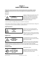
SAFETY PRECAUTIONS
GENERAL CONSIDERATIONS
SERVICING EQUIPMENT
1. Read and follow these instructions. Failure to do
this could result in severe personal injury or death.
1. Only trained personnel are to operate and service
equipment.
2. Additional safety instructions and/or symbols are
located throughout this manual. They serve to warn
maintenance personnel and operators about
potentially hazardous situations.
2. Never service equipment while it is in motion.
3. Inspect the machine for unsafe conditions daily
and replace all worn or defective parts.
3. Shut off the equipment and lock out all input
power and air supply at their sources before
attempting any maintenance.
4. Follow the maintenance and service instructions in
the manual.
4. Keep work area uncluttered and well lit.
SIGNS
5. All covers and guards must be in place before
operating this equipment.
For precautions and definitions of safety symbols,
refer to Safety Chapter of the service manual.
1. Read and obey all of the warning labels, signs and
caution statements on the equipment.
2. Do not remove or deface any of the warning labels,
signs, and caution statements on the equipment.
3. Replace any warning labels, signs, and caution
statements which have been removed or defaced.
Replacements are available.
ADDITIONAL CONSIDERATIONS
1. To ensure proper operation of the equipment, use
specified electrical and/or air supply sources.
2. Do not attempt to alter the design of the
equipment unless written approval is received from
our factory.
3. Keep all manuals readily accessible at all times and
refer to it often for the best performance from your
equipment.
TABLE OF CONTENTS
Chapter 1 Safety Precautions
Chapter - Page #
Chapter 2 Description & Specifications
Description ............................................................................................................................................
2-1
Specifications ........................................................................................................................................ 2 - 2
Dimensions ............................................................................................................................................ 2 - 3
Chapter 3 Installation & Start Up
Mounting & Lifting ASU ....................................................................................................................
3-1
Installation .............................................................................................................................................
3-2
Adding Adhesive .................................................................................................................................
3-3
Changing Adhesive Formula ........................................................................................................... 3 - 3
Wattage Availability Chart ...............................................................................................................
3-4
Typical Start Up & Shut Down Procedures .................................................................................
3-4
Storage & Disposal of the Application System .........................................................................
3-5
Chapter 4 Temperature Controller Set-Up
Temperature Control Functions in General ...............................................................................
4-1
Defining Temperature Control Terms .......................................................................................... 4 - 1
Error Indication Message ..................................................................................................................
4-2
Firmware Chip & Checksum ............................................................................................................
4-3
System Values .......................................................................................................................................
4-3
Helpful Hints .........................................................................................................................................
4-4
Chapter 5 Programming of the Controller
Controller Keypad ...............................................................................................................................
5-1
Programming ........................................................................................................................................ 5 - 2
Service Functions ................................................................................................................................
5-4
Controller Features .............................................................................................................................
5-9
Optional Features ................................................................................................................................ 5 - 10
©Astro Packaging
AP50 Manual-19600-09-AP50
Chapter 6 Preventive Maintenance
General Cleaning .................................................................................................................................
6-1
Purging Manifold of Adhesive and Pressure .............................................................................
6-1
Output Filter .......................................................................................................................................... 6 - 2
Hose Fittings and Fasteners ............................................................................................................. 6 - 3
Tank Screen Cleaning ......................................................................................................................... 6 - 3
Summary of Preventative Maintenance .....................................................................................
6-4
Chapter 7 Troubleshooting
General Troubleshooting .................................................................................................................. 7 - 1
Handling Printed Circuit Boards ....................................................................................................
7-1
Control Printed Circuit Boards ........................................................................................................
7-2
Over-temp Thermostat ...................................................................................................................... 7 - 3
Tank Over-current ...............................................................................................................................
7-3
Ready Contact to Parent Machine ................................................................................................. 7 - 3
Temperature Zones Not Heating ...................................................................................................
7-3
Location of PCB, Circuit Breaker, Over-temp Thermostat Re-set & RTD Sensor ............ 7 - 2
Resistance Tables .................................................................................................................................
7-4
Troubleshooting Guide .....................................................................................................................
7-5
Piston Pump Troubleshooting Guide ...........................................................................................
7-9
Chapter 8 Disassembly & Re-assembly Procedures
To Access Electrical Parts ..................................................................................................................
8-1
Printed Circuit Board Replacement ..............................................................................................
8-2
Re-assembly Procedures & Cautions ............................................................................................
8-3
Chapter 9 Component Illustrations & Bills of Material
Pumps, V2 & Accessories ..................................................................................................................
9-2
Standard Fan-Cooled Motors ..........................................................................................................
9-3
©Astro Packaging
AP50 Manual-19600-09-AP50
Chapter 10 Component Illustrations
Hose Schematic: all models .............................................................................................................
10 - 1
Head Schematic: all models ............................................................................................................
10 - 2
Wiring Diagram
10 - 3
©Astro Packaging
AP50 Manual-19600-09-AP50
Chapter 1
SAFETY PRECAUTIONS
All operators and service personnel must read and understand this manual before servicing
equipment. All maintenance and service on this equipment must be performed by trained
technicians.
Electrical
DANGER
HIGH VOLTAGE
Dangerous voltages exist at several points in this
equipment. To avoid personal injury, do not
touch exposed connections and components
while input power is on. Disconnect, lockout
and tag external electrical power before
removing protective panels.
A secure connection to a reliable earth ground is essential for safe operation.
A disconnection switch with lockout capability must be provided in the line ahead of the unit. Wiring used
to supply electrical power should be installed by a qualified electrician.
High Temperatures
WARNING
HOT
SURFACE
Severe burns can occur if unprotected skin
comes in contact with molten adhesive or hot
application system parts.
Safety glasses, gloves, and long-sleeved clothing
must be worn whenever working with or around
adhesive application systems.
High Pressure
WARNING
HIGH PRESSURE
PRESSURE
To avoid personal injury, do not operate the
equipment without all covers, panels, and safety
guards properly installed.
To prevent serious injury from molten adhesive
under pressure when servicing the equipment,
disengage the pumps and relieve the adhesive under pressure (e.g. trigger the heads, hand-held
applicators, and/or other application devices into a waste container) before opening any hydraulic fittings
can connections.
Protective Covers
Keep all guards in place!
WARNING
DO NOT OPERATE
WITHOUT GUARDS
IN PLACE
©Astro Packaging
To avoid personal injury, do not operate the
application system without all covers, panels,
and safety guards properly installed.
AP50 Manual-19600-09-AP50
1-1
Eye Protection & Protective Clothing
WARNING
It is very important that you PROTECT YOUR
EYES when working around hot melt adhesive
equipment !
EYE PROTECTION
REQUIRED
Wear glasses with side shields which conform
to ANSI Z87.1 or EN166
Failure to wear safety glasses could result in
severe eye injury.
PROTECTIVE
CLOTHING
REQUIRED
It is important to protect yourself from
potential burns when working around hot
melt adhesive equipment.
Always wear steel reinforced safety shoes.
Wear protective gloves and long-sleeved, protective clothing to prevent burns that could result from
contact with hot material or hot components.
_________________________________________________________________________________________
Safe Installation and Operation
To avoid possible failure of hoses, make sure all hoses are routed to avoid kinking, tight radius turns (8” or
less) and abrasive contact. Hot-melt hoses should not have prolonged contact with heat-absorbing
surfaces such as cold floors or metal troughs. These heat-absorbing surfaces can alter adhesive flow and
cause incorrect calibration. Hoses should never be covered with materials that precent heat dissipation,
such as insulation or sheathing.
Read this manual before applying electrical power to the equipment. Equipment may be damaged by
incorrect electrical connections.
Do not use adhesive that is dirty or that may be chemically contaminated. Doing so can cause system
clogging and pump damage.
When adhesive hand-help applicators or other movable applicators are used, never point them a yourself
or at any other person. Never leave a hand-held applicator’s in use.
Do not operate the tank or other system components without adhesive for more than 15 minutes if the
temperature is 150 degrees C (300 degrees F) or more. To do so will cause charring of the residual adhesive.
Never activate the heads, hand-held applicators and/or other application devices until adhesive’s
temperature is within the operating range. Severe damage could result to internal parts and seals.
_________________________________________________________________________________________
Treatment for Burns From Hot Melt Adhesives
Burns caused by hot melt adhesives must be treated at a burn center.
©Astro Packaging
AP50 Manual-19600-09-AP50
1-2
Care should be used when working with hot melt adhesives in the molten state. Because they rapidly
solidify, they present a unique hazards.
Even when first solidified, they are still hot and can cause severe burns. When working near a hot melt
application system, always wear safety gloves, safety glasses and long-sleeved, protective clothing.
Always have first-aid information and supplies available.
Call physician and/or an emergency medical technician immediately.
_________________________________________________________________________________________
Service
Refer all servicing to qualified personnel only.
_________________________________________________________________________________________
Explosion/Fire Hazard
Never operate this unit in an explosive environment.
Use cleaning compounds recommended by Astro Packaging. Flash points of cleaning compounds vary
according to their composition, so consult with your supplier to determine the maximum heating
temperatures and safety precautions.
_________________________________________________________________________________________
Lockout/Tag-out
Follow OSHA 1910.147 (Lockout/Tag-out Regulation) for equipment’s lockout procedures and other
important lockout/tag-out guidelines.
Be familiar with all lockout sources on the equipment.
Even after the equipment has been locked out, there may be stored energy in the application system,
particularly capacitors within the panel box. To ensure that all stored energy is relieved, wait at least one
minute before servicing electrical capacitors.
_________________________________________________________________________________________
In This Manual
WARNINGS and CAUTIONS are found throughout the manual.
WARNINGS mean that failure to observe the specific instructions may cause injury to personnel.
CAUTIONS mean that failure to observe the specific instructions may damage the equipment.
©Astro Packaging
AP50 Manual-19600-09-AP50
1-3
Chapter 2
DESCRIPTION AND SPECIFICATIONS
Description
The Astro Packaging AP50/AP100 adhesive supply unit (ASU) is a computer-controlled hotmelt supply unit designed on metric standards. Its easy-to-use, all-icon control panel is
internationally operator friendly. The AP50/AP100 is available for either 240V/400V service.
The AP50/100 uses a microprocessor temperature control to closely control the temperature
of hot-melt adhesive for up to six hoses and six heads. Temperature set points are operatorselected for up to thirteen zones and the system automatically provides warnings and alarms
for operator errors and system malfunctions.
The system provides accurate, proportionate temperature control for the tank, hoses, and
applicators. Sequential start-up delays may be programmed for turn-on of the hoses and
heads. A “standby” temperature may be programmed so that the temperature zones can be
maintained at a lower temperature when the ASU is not in active use, enabling rapid return to
normal operation.
The temperature control can interlock the parent machine with preselected adhesive
temperatures so that production automatically begins when adhesive temperatures are
correct for the application. All system temperature values can easily and quickly be
programmed.
With these flexible temperature programming features, the system increases adhesive life by
eliminating prolonged high adhesive temperatures. It reduces energy consumption and
brings the system up to normal operating temperatures in the shortest possible time.
The standard AP50/AP100 ASU uses a brushless AC motor to drive a positive displacement
gear pump. This gear pump has an easily adjustable flow control. The pressure can be
adjusted from 75 PSI to a maximum of 900 PSI.
The ASU’s Teflon-coated tank accepts adhesive in all popular forms, including pellets, slugs
and blocks. The ASU can accommodate air-actuated automatic applicators (heads), electric
applicators, hand-held applicators and/or special applicators. Options available include
pressure gauge, a 40-mesh outlet filter, 7-day scheduler and RS-232 interface.
©Astro Packaging
AP50 Manual-19600-09-AP50
2-1
Specifications
Environmental:
Storage/shipping temperature.....................................................................-40˚C to 70˚C (-40˚F to 158˚F)
Ambient service temperature...........................................................................-7˚C to 50˚C (20˚F to 122˚F)
Noise Emission....................................................................................................................<60 dbA (at 1 meter)
Physical:
Dimensions .................................................................................. dimensional layouts on following pages
Number of heads/hoses ................................................................................................. up to 6 heads/hoses
Number of tank temperature zones ..................................................................................................................1
Number of pumps ....................................................................................................................................................1
Gear pump pressure range of............................................................................................... 75 PSI to 900 PSI
Enclosure.......................... styled, durable metal and high temp plastic, dust and splatter resistant
Hose connections....................................................................................................................... Electrical:12-pin
Mechanical: wrench-secured fluid fittings (#06 37˚ SAE)
Tank Capacity ..................................................................................................................................22.5 kg/50 lbs.
Tank Construction ........................................................................... welded aluminum, TFE Teflon coated
Filtration ..................................................................................................................... pre and post pump filters
Weight, empty..................................................................................................................................50 kg/ 100 lbs.
Adhesive form ...............................................................accepts most forms (no water-based adhesives)
Electrical:
Supply voltage ................................................................................240/400 VAC/ 3PH + N 60 Hz (Y, “WYE”)
............................................................................................................................240 VAC/ 3PH 60 Hz (Δ, “DELTA”)
........................................................................................................................... 240 VAC/ 1PH 60 Hz (Δ, “DELTA”)
Power Consumption, system maximum ......................................................................................9600 watts
Power Consumption, tank...................................................................................3000 Watts, 4000 Optional
Tank Heater Type ...................................................................................................replaceable cartridge style
Temperature control..................................................................................................................micro-controller
Temperature sensors ..................................................................................................................Ni120 standard
Electrical connectors...........................................................durable, latching connectors, Nordson-style
Maximum current available for each hose/head combination ...................................................5 amps
©Astro Packaging
AP50 Manual-19600-09-AP50
2-2
Performance:
Adhesive temperature control range ......................................................40˚C to 218˚C (100˚F to 425˚F)
Adhesive temperature control accuracy .................................................................................. ± 1˚C (± 1˚F)
Over-temperature cutoff for all zones ..................................................................................... 232˚C (450˚F)
Over-temperature cutoff for tank thermostat ...................................................................... 224˚C (435˚F)
Adhesive Viscosity .....................................................................................................500 to 50,000 centipoise
Warm-up time, full tank .............................................................................................approximately 0.5 hour
Adhesive delivery rate, open line .................................................................................................2.91 lbs/min
Adhesive melt rate (depends on adhesives used) ........................................................................50 lbs/hr
Adhesive pressure ................................................................................... up to 68 bar (1000 PSI) maximum
Maximum pump speed ...........................................................................................................................170 rpm
Temperature Controller:
Controller Board .............................................................................................1 board, modular construction
Display type ..........................................................................................................................life-long, bright LED
Temperature control zones ................................................................................................................................13
Fuses .................................................................................................................all fuses are size 5 mm x 20 mm
hose/ applicator head: 6.3 amp fast open
transformer: 1 amp, fast
tank: 10 amp fast
Other:
Operator interface ...........................................................digital display with simplified, all-icon keypad
Seven-day scheduler ....................................................................................................................................option
RS232 interface ..............................................................................................................................................option
Temperature standby .........................................................................................................................................yes
High & low temperature tolerance ................................................................................................................yes
Ready interlock contact .....................................................................................................................................yes
Sensor open alarm ...............................................................................................................................................yes
©Astro Packaging
AP50 Manual-19600-09-AP50
2-3
©Astro Packaging
AP50 Manual-19600-09-AP50
2-4
Chapter 3
INSTALLATION & START-UP
Mounting the AP50/AP100 ASU
The AP500/100 ASU can be mounted on most flat surfaces, on either an open or a solid frame (as shown
below). The main electrical power and the serial communication connections come in from below the unit
and connect under the keypad. Access to the underside of the ASU may be necessary and an “open” frame
mount is generally best.
For installation dimensions, see illustration on page 2-4.
Lifting the ASU
WARNING
The unit must be lifted by two persons, using proper lifting technique, one
person at either end. Securely hold it under its base plate. No belts or hooks
should be used. Never allow anyone to stand on the ASU.
©Astro Packaging
AP50 Manual-19600-09-AP50
3-1
Installation
NOTE: Re-read Chapter 1 “Safety Precautions” before performing any installation procedures. All
installation procedures must be performed by qualified, trained technicians.
After the AP50/AP100 ASU has been properly mounted, the following general sequence should be followed
for installation:
1. Make sure that incoming line power to the ASU and the unit’s main power switch
are turned OFF.
2. Your power supply should be rated for 30 Amp service and should include an earth
ground conductor.
3. Make two connections to the printed circuit board: Loosen the 3 button head screws on the top. Front door
will open forward.
a. Select proper power configuration plug for your system (two
plugs are shipped with the unit. You must install one of these):
CAUTION: Using the incorrect power configuration
plug may cause serious damage to the unit.
for 230 VAC, 3PH, Delta = use PN 112542
white plug with violet wire
for 230/400 VAC, 3PH, WYE = use PN 112543
white plug with yellow wire
for 230 VAC, 1 PH, Delta = use PN 112543
white plug with yellow wire
(you will need to add jumpers, see below)
b. Insert proper power configuration plug into socket J1 at bottom, center of control printed circuit board
located within the control enclosure (see illustration of PCB in Chapter 7 for location).
c. Wire main power into Line Input Power Plug and the ground lug. Main power connections & the ground
lug are at the bottom, left of the PCB (X1). Conduit fitting or cable grip not supplied.
©Astro Packaging
AP50 Manual-19600-09-AP50
3-2
4. The adhesive hoses are connected under the unit. You must make both an electrical and an adhesive flow
connection. The electrical hose connections are at the six numbered rectangular receptacles on the front end
panel.
The hose adhesive ports are located to the at the bottom of the unit. There are six ports (fittings) for the use
of up to six hoses. They may be routed out the front, back or down from the unit.
When making hose connections, follow the number guide label on the ASU above the hose socket; i e. when
using one hose make your hookup to electrical connection #1 and adhesive port #1. When using two heads/
hoses, connect hose/ head #1 to electrical connection #1 and adhesive port #1, then hookup hose/ head #2
to electrical connection #2 and adhesive port #2. In a similar manner, connect the remainder of your hose(s)/
head(s).
Route hoses so that there is at least an eight-inch radius at any bend. Do not hang hoses without proper
support. Do not crimp, clamp, squeeze or tie hoses. Refer to the hose and applicator manuals for further
details on these items.
Adding Adhesive
The adhesive level should be maintained at 13 mm to 100 mm (1/2” to 4”) from the top of the tank. Where
applications demand a high output volume of adhesive, add small amounts of adhesive frequently. ADDING
LARGE AMOUNTS OF ADHESIVE TO AN ALMOST EMPTY TANK WILL LOWER THE TEMPERATURE OF THE
ADHESIVE IN THE TANK AND MAY CAUSE THE ASU TO FALL BELOW ITS READY SET-POINT.
Changing the Adhesive Formula
If a different adhesive formulation from the one being currently used is needed, the system will have to be
flushed if the two formulations are incompatible. See Chapter 6 of this manual for the proper flushing
procedure. When in doubt about adhesive compatibility, flush your system.
©Astro Packaging
AP50 Manual-19600-09-AP50
3-3
Wattage Availability Chart
ASU Voltage
240/400 VAC(Y)
or
240 VAC (Delta)
Max. System Wattage
9600 @ 240VAC
Hopper Wattage
3000 @ 240VAC
Wattage Available for
All Hoses and Heads
6600 @ 240VAC
Notes:
1. Assume 33 Watts per foot of hose, #6 hose at 240VAC.
2. Assume 100 Watts per inch of head width, at 240VAC.
3. The power available for any one hose/head combination is 1200 Watts at 240VAC.
4. AT REDUCED VOLTAGE, LESS WATTAGE IS AVAILABLE. FOR EXAMPLE: 240V EQUIPMENT OPERATED ON 200
VOLTS, WILL DEVELOP WATTAGE 31% LOWER THAN THE WATTAGE AVAILABLE AT 240 VOLTS.
Typical Start-Up and Shut Down of the AP50/AP100 Application System
Start-Up Procedures
1. Fill the ASU’s tank with clean hot-melt adhesive as described on page 3-3. Close the tank lid immediately
to prevent contaminants from falling in. (Cover your bulk supply of adhesive to prevent contaminants
also.)
2. At the control panel, turn ON the Main Power Switch. The controller will perform its initial
calibration cycle. The display will read “CAL”. Each of the 13 temperature zone’s LEDs will flash
as a lamp test.
3. Program your adhesive set-points (see instructions on page 5-2) or use the factory settings listed below.
Allow adequate time (approximately 20-30 min.) for the adhesive to melt and the temperatures of the
temperature zones to stabilize. Note: When the ASU leaves Astro Packaging, it is programmed with the
following factory settings (unless special factory settings were requested):
Tank: 177°C (350°F)
Hose: 177°C (350°F)
Applicator: 177°C (350°F)
Sequential Startup: OFF
4. Once the ASU has reached temperature, the ASU will begin to pump adhesive.
NOTE: A DELAY MAY BE PROGRAMMED AT CONTROLLER
5. Adjust the flow control with the provided 1/4” Allen wrench to desired pressure.
Shut Down Procedures
1. Turn OFF the Main Power Switch
©Astro Packaging
AP50 Manual-19600-09-AP50
3-4
Storage and Disposal of the AP50/AP100 Application System
Temporary Storage of the Unit
1. Flush the adhesive application system with flushing fluid (PN RB-5), following the instructions detailed in
Chapter 6 of this manual.
2. Clean or replace both the output filter and the tank, following instructions detailed in Chapter 6.
3. Shut OFF all pressure and power sources.
4. Remove all residual adhesive and wipe components clean.
5. Remove all power supply cables.
6. Pack the unit in a corrosion-proof manner.
7. Store the unit in such a way that it is protected from damage.
Disposal of the Unit
1. Shut OFF all pressure and power sources.
2. Remove all residual adhesive.
3. Remove all adhesive supply hoses and all power supply cables.
4. Dismantle all components and sort into mechanical and electrical components.
5. Arrange for all components to be recycled.
©Astro Packaging
AP50 Manual-19600-09-AP50
3-5
Chapter 4
TEMPERATURE CONTROLLER SET-UP
Temperature Control Functions in General
The AP50/AP100 temperature controller provides accurate temperature control for the hopper, hoses and
applicators. Set-points are programmed at the user-friendly, all-icon keypad. The controller will display an
error message any time an open or shorted sensor condition occurs.
Defining Temperature Control Terms
Adhesive Temperature Control Range
The temperature limits within which the ASU, hoses and applicators may be programmed and maintained.
Alarm Signal
The controller provides an alarm signal if any zone has a critical situation. This signal is available on a dry
contact located at connector X10 on the Control printed circuit board.
CPU Module
The central processing unit (CPU) of the microprocessor temperature control.
Temperature Controller
The built-in control system that controls, monitors and displays all system temperature values of the
adhesive application system.
Control PCB
The printed circuit board (PCB) of the ASU. It provides control signals to, and monitoring signals from, the
tank, hoses and applicators. It features lighted LEDs to indicate that heater power is ON. The ASU’s fuses
and power configuration plug are located on this board.
Keypad Locking
The controller’s keypad may be locked (or unlocked) to restrict (or allow) further programming.
Mechanical High-Temperature Protection
A mechanical, redundant thermostat located on the hopper that will turn off the system above safe
temperatures
RTD Sensors
The system uses 120-ohm Nickel resistance temperature detector (RTD) sensors for all temperature
controls.
Ready Signal
The controller provides a ready signal if all temperature zones are within a programmable tolerance and the
system is ready for production. This signal is available on a dry contact at connector X11 on the Control
printed circuit board. The ready signal also controls pump operation.
©Astro Packaging
AP50 Manual-19600-09-AP50
4-1
RS232 Remote I/O Interface
Bi-directional data transfer to a remote computer is available for the controller via the RS232 option. The
ASU’s RS232 serial port connection allows remote interface up to 50 meters from the AP50/AP100
controller.
Sequential Startup
This feature allows the temperature zones to come on in sequence (tank followed by hoses and heads).
When activated, and the ASU is turned ON from a cold start, the tank heats first. When the tank is within its
set-point tolerances, the hoses and heads begin to heat.
Set-point
A programmable temperature that has been selected for tank, hoses and applicators.
Set-point Limitation
This is a universal maximum temperature for all zones (218°C [425°F]). The programmer cannot program a
temperature set-point higher than the set-point limitation.
Seven-Day Scheduler
This option enables the controller to provide scheduling of ON and OFF operating modes for the ASU’s
system at the keypad. It therefore allows the operator to program ON and OFF heating cycles which
coincide with his production schedule throughout the work week. The scheduler helps conserve electricity
usage and functions also as an additional safety feature.
Standby (Setback)
During breaks or delays in production, it is possible to reduce the temperature of all zones by a specified
amount through programming of a standby. The programmed standby (also referred to as “setback”) is the
difference in temperature by which all zones will reduce below their set-points when standby is activated.
Standby is always OFF when the ASU is turned ON. In standby mode, the ready signal is OFF and the pump
will stop.
Error Indication Messages
A controller display of “EO1” indicates that the selected zone (ie, a hose, applicator or the tank) has an open
sensor. A display of “EO2” indicates a shorted sensor.
If either alarm occurs, first verify that the following three connections are made correctly:
1. The ASU-to-hose connection(s) located at the back of the ASU,
2. The hose-to-applicator connection(s),
3. The RTD Input connections (X4, X5 & X6) located on the Control Printed Circuit Board.
If the problem is not with a connection, check the sensor and replace if necessary.
©Astro Packaging
AP50 Manual-19600-09-AP50
4-2
Firmware Chip and Checksum
The firmware chip is on the Control Printed Circuit Board (see Ch. 7). Inscribed on the controller’s chip is
information that is required if your controller needs service, including the controller’s checksum and
software revision.
Chip example:
System Values That Are Permanently Programmed
· Minimum set-point value: 40°C (100°F).
· Maximum set-point value: 218°C (425°F).
System Values as Programmed by the Factory
Astro Packaging can set the controller’s system values to customer’s specs, if provided.
If customer’s specs are not provided, the following values will be entered into the temperature controller at
the factory. They may be changed by reprogramming through the keypad.
• Temperature Scale: displayed in degrees Fahrenheit
• Applicator (head) and hose set-points: OFF
• Tank Set-point: 177 C° (350°F)
• All zones are switched off, except for the tank
• Access Code: not active
• All programmable time delays: set to zero (0)
• Tolerance range for high & low temperature limits ±27°C (±50°F)
©Astro Packaging
AP50 Manual-19600-09-AP50
4-3
Helpful Tips for the User
• When the ASU is turned on, all temperature set-points and other operating parameters will be exactly
where they were when the ASU was turned off.
• When the ASU is turned on, all system heaters go on unless they have previously been set below 40°C
(100°F) (ie. switched OFF).
• When the ASU is turned on , the controller checks all RTDs. If a zone does not have a valid RTD, this zone
will be switched off.
• WHEN THE ASU IS TURNED ON AND THE PUMP SWITCH IS TURNED ON THE PUMP WILL AUTOMATICALLY
RUN WHEN ALL SET-POINTS ARE REACHED.
©Astro Packaging
AP50 Manual-19600-09-AP50
4-4
Chapter 5
CONTROLLER PROGRAMMING INSTRUCTIONS
Controller Keypad
©Astro Packaging
AP50 Manual-19600-09-AP50
5-1
Programming
Turn Controller ON
Turn ON the main power switch
System will go through its self-diagnostics (CAL).
Controller will display “CAL”.
Temperature zone LEDs will flash.
Controller will display “SS 1” (On) or “SS 0” (Off) to
indicate status of the Sequential Startup feature
(see info on “Sequential Startup” later in the chapter).
Controller will display firmware version, ie. VX.XX
Programming Temperature Set-points
(for a shortcut method of setting set-points, see “To
Copy & Paste Set-points” on pg. 5-9)
Choose a temperature zone.
When flashing, the zone’s set-point is displayed, and
it can be programmed.
In order to program the temperature set-point, scroll
up to increase value or down to reduce value.
After two seconds the display will read the actual temperature.
The set-point is stored.
Turning Temperature Zones ON/ OFF
Choose a temperature zone.
Scroll to reduce value until the temperature set-point
shows “ -- -- -- ”. This temperature zone is now
turned OFF.
To turn ON the temperature zone, increase the
set-point.
When programming is complete, wait a few
seconds and the controller will return to the ASU’s
actual temperature.
©Astro Packaging
AP50 Manual-19600-09-AP50
5-2
Keypad Locking
It is possible to lock or unlock the controller in order to restrict programming changes. To change the code
which is necessary to over-ride or unlock the keypad lock, see Service Functions.
Note: the ASU is shipped with de-activated keypad lock. If the keypad lock must be used, an access code must be
programmed prior to locking the keypad.
Locking or Unlocking the Keypad
Important Note: the controller must be in the Temperature Display mode in order to allow
locking or unlocking of the keypad.
Locking the Keypad
Press the Down Scroll key, then hold and press the
Service icon key.
You will see “Loc” to indicate that the Keypad Lock is
active.
Unlocking the Keypad
Press the Down Scroll key, then hold and press the
Service icon key.
You will see “Cod” to indicate that the access code is
required.
Enter your access code by scrolling up or down.
Confirm your code input by pressing Tank key.
Notes:
1. Once the keypad lock is active, unauthorized programming is not possible, even after turning the
ASU OFF, then back ON again.
2. Once the keypad lock is unlocked, programming is possible until the ASU is turned OFF, then
back ON or the keypad is locked again.
3. If the keypad must be unlocked permanently, the access code must must be de-activated in the
Service Functions.
©Astro Packaging
AP50 Manual-19600-09-AP50
5-3
Service Functions
After the basic programming of Temperature Set-points is complete, the programmer proceeds to
programming of the Service Functions, if desired.
The Service Functions are a continuous loop of programming steps (”functions”) which the programmer
moves through by pressing the “Service” key. These steps are described in this section of the chapter. The
Service Functions loop and basic programming is diagrammed below.
There are three ways to exit the Service Functions loop:
1. Just wait (approx. 10 seconds) and the controller will automatically return to the actual
temperatures display,
2. Press the Service key until you are back to the actual temperatures display, or
3. Press any Hose or Head key and you will return to the actual temperatures screen.
Diagram of the
Service Functions Loop
©Astro Packaging
AP50 Manual-19600-09-AP50
5-4
Service Functions, cont.
Standby Programming
“Standby” is a temperature value by which all temperature zones will lower when Standby mode
is activated. For example, if your temperature set-points are all 300 degrees, and you program a
100 degree Standby, then the Standby temperature of all zones will be 200 degrees. Similarly, if
your temperature zones set-points vary, and you program a 100 degrees Standby, each zone’s
Standby temperature will be 100 degrees lower than its set-point.
Press Service icon to enter Service Functions.
You will see either “S--1” (standby is On) or “S--0”
(standby is Off).
Press the Tank icon to activate/ de-activate Standby.
If desired, you may set the Standby temperature by
scrolling up or down to desired temperature.
When programming is complete, wait a few seconds
and the controller will return to the ASU’s actual
temperature.
Note: When Standby is active, the display will alternate between the ASU’s actual temperature
and S--1.
©Astro Packaging
AP50 Manual-19600-09-AP50
5-5
Service Functions, cont.
To Set Tolerance (Hi & Low Temperature Limits)
The Tolerance (high/ low alarm) set-point is a range (+ and -- the zone’s temperature set-point) between
which your ASU can safely operate. It’s lower temperature represents the ASU’s ready
temperature. It’s upper value represents the over-temperature point.
Setting the Tolerance range, for example: if the temperature set-point is 200 degrees, and the Tolerance
set-point is 10 degrees, then the high alarm equals 210 degrees and the low alarm (ready
temp) equals 190 degrees.
Press the Service icon twice to select the Tolerances of your
temperature zones. An display of “t--1” indicates the Tolerance
function has been selected.
Press the Tank button to display the Tolerance.
Use the scroll buttons to change the Tolerance range for all zones.
Note: your Tolerance range must be a value between ± 50 degrees
for Fahrenheit (± 27 degrees for Celsius).
When Tolerance programming is complete, wait a few seconds and
the controller will return to the ASU’s actual temperature.
Turning Sequential Startup ON/OFF
The Sequential Startup feature programs the order in which the temperature zones will come on at
startup. A Sequential Startup” of “SS1” (On) means the tank will begin heating first, then, when the
hopper is ready, the other zones will begin heating. A Sequential Startup of “SSO” means Sequential
Startup is Off and all zones will begin heating immediately.
Press the Service icon three times to set Sequential Startup.
The display will flash either “SS1” (sequential startup is ON) or
“SS0” (sequential startup is OFF).
Scroll to choose between ON and OFF. When programming is
complete, wait a few seconds and the controller will return to
the ASU’s actual temperature.
Note: Any time the ASU is switched ON, you will briefly see
“SS1” or “SS0” displayed.
©Astro Packaging
AP50 Manual-19600-09-AP50
5-6
Service Functions, cont.
To Set Temperature Scale
The Temperature Scale may be set to display temperature either in degrees Celsius or Fahrenheit.
Press the Service icon four times to set the Temperature
Scale.
Scroll to choose between Celsius (”C”) or Fahrenheit
(”F”) as indicated by the Temperature Scale LED. When
programming is complete, wait a few seconds and the
controller will return to the ASU’s actual temperature.
To Set Ready Delay
When the system is ready (all temperature zones are within tolerance), a ready delay may be programmed
to delay the system’s ready output signal.
Press the Service icon five times to set a Ready Delay.
You will see “d--1” to indicate you are in Ready Delay
programming mode.
Press the Tank icon to display the Ready Delay.
To change a Ready Delay, scroll up or down to the
desired length (in minutes) of delay.
0 = Default, no delay
99 minutes = maximum length of delay
When programming is complete, wait a few seconds and
the controller will return to the ASU’s actual temperature.
©Astro Packaging
AP50 Manual-19600-09-AP50
5-7
Service Functions, cont.
To Change Access Code (De-activate Keypad Locking)
To change the Access Code, press the Service icon six
times.
You will see “C--1” to indicate you are in Access Code
programming mode.
Press the Tank icon to see the programmed Access
Code. For example, “999”.
To change the Access Code, scroll up or down to the desired
numeric value.
“-- -- --” = no Access Code (Access code is de-activated),
1 - 999 = possible Access Code values
When programming is complete, wait a few seconds and the controller will return to
the ASU’s actual temperature.
©Astro Packaging
AP50 Manual-19600-09-AP50
5-8
Controller Features
System Ready Indicator Light
When not in programming mode, a flashing temperature scale light
(LED) indicates that the ASU is not “Ready” for production. This LED
will cease to flash when all temperature zones are within the programmed
temperature tolerance window.
Error Indication Messages
“EO1” = the temperature sensor is open (no sensor attached) or has
high resistance.
“EO2” = the temperature sensor is shorted or has low resistance.
“EO3” or “EO4” = an internal error has occurred. The printed circuit
board or the ASU must be returned to Astro Packaging for re-calibration.
“o -- t” = over-temperature on any zone. Power to all heaters is
switched OFF. Recycle power (re-boot) and check which zone has
caused the fault alarm.
To Copy and Paste Set-points
The Copy/ Paste feature of the controller copies the tank set-point and pastes it as the set-point of
other temperature zones. The paste will apply to only temperature zones that are switched ON.
Set your Tank set-point as described earlier in this chapter.
Push and hold the Tank icon. While holding, press the #1 Hose icon. Release.
Push and hold the Tank icon again. While holding, press the #1 Head icon. Release.
The manually programmed set-point has now been pasted in to all turned on hose
and head zones. When programming is complete, wait a few seconds and the
controller will return to the ASU’s actual temperature.
©Astro Packaging
AP50 Manual-19600-09-AP50
5-9
Programming of Optional Features
Seven-Day Scheduler
The Seven-Day Scheduler allows the operator to program main power ON and OFF times which
coincide with his daily production schedule throughout the work week. Up to 20 “switching times”
may be scheduled. A switching time is a specific day, time and state.
An ASU which has an active seven-day scheduler should be turned ON at the main power switch. It
should never be turned off by the main power switch while the scheduler is active. To turn the ASU
OFF (temporarily overriding the scheduler), use the seven-day scheduler’s manual operation key.
If the scheduler switches the ASU OFF, the controller’s main display will say “OFF”. To re-activate
the ASU (over-ride the scheduler), press the scheduler’s manual operation icon (at the lower, right
on the scheduler display) once or twice. Later, to return the scheduler to active, press the manual
operation icon again until the the automatic operation’s clock icon (at upper, right on display) re-appears.
For additional information on the scheduler, see the Appendix in this manual.
Schedular Display
Time and Day Programming
Press the Time key and hold throughout the following procedure.
Set the day of the week with the Day key (1= Monday, 2 = Tuesday... 7=Sunday).
Set the desired hour with the h key.
Set the desired minutes with the m key.
Release the Time Key.
The colon will now flash.
©Astro Packaging
AP50 Manual-19600-09-AP50
5-10
Setting the Switching Commands
The programmer must set the desired days of the week, switching times and switching state.
Select the Free Memory Spaces
Press the Prog. key (as necessary) until the digits 1 thru 7 are visible.
Release the Prog. key.
Select the Desired Days of the Week
Press the Day key to select any single day or any combination of days.
Monday = 1, Tuesday = 2...Sunday = 3.
Select the Desired Switching Times
Press the h key to select the hours.
Press the m key to select the minutes.
Select the Desired Switching State
Press the Manual Operation Selection key to toggle the switching state. The symbol will
indicate the state.
Symbol:
= ON
= OFF
Press the Prog. key once to end.
Repeat for Further Switching Commands
Repeat the last three steps for programming of additional switching commands.
End Programming of Switching Commands
Press the Time key once. The display will show the current time.
Select Manual ON/ OFF
Press the Manual Operation Selection key to select manual mode ON or OFF.
= manual mode ON
= manual mode OFF
©Astro Packaging
AP50 Manual-19600-09-AP50
5-11
Chapter 6
PREVENTATIVE MAINTENANCE
Note: Re-read Chapter 1 “Safety Precautions” before performing any maintenance procedures. All
maintenance procedures must be performed by qualified, trained technicians.
General Cleaning
The AP50/AP100 ASU enclosure is finished with an extremely durable powder coating. The enclosure may
be cleaned with a variety of industrial cleaners following manufacturers’ directions. To prevent
discoloration or deterioration of the ASU’s finish, avoid prolonged contact with strong solvents.
Preventive Maintenance Schedule
The AP50/AP100 ASU requires little maintenance. The tank is fitted with a coarse screen to prevent large
debris from entering the system. Normally this screen does not require cleaning. The ASU parts that
require regular, periodic maintenance are as follows:
Purging the Filter Manifold of Adhesive and Pressure
As a safety precaution, the ASU’s system should be purged of pressure and adhesive before
attempting to change the output filter or before removing any of the hoses or applicators from their
manifold port.
Refer to the illustration on page 6-2 while following these instructions.
WARNING
HIGH PRESSURE
During the purging procedure, hot adhesives can come out of the manifold
under high pressure. Wear a face shield, gloves and protective clothing.
Stand clear of the ASU until all pressure is relieved.
HOT ADHESIVE
Avoid splashing hot adhesive. Position a heat-resistant container under the
manifold’s purge drain before proceeding.
The ASU should be at operating temperature. Turn the ASU’s motor OFF.
1. Locate the bleed valve on the output filter manifold.
2. With a hex key screwdriver (allen wrench), slowly loosen the purge screw (do not attempt to remove it)
which is in the bleed valve’s port. Allow the adhesive and pressure to escape outof the manifold. The
adhesive will flow into the heat-resistant container positioned below the manifold.
©Astro Packaging
AP50 Manual-19600-09-AP50
6-1
Output Filter
The output (pump filter should be replaced monthly during the first few months of operation. After you
gain experience with your system, you can determine how often you need to replace it. The output filter is
located on the pump manifold on the hose connection panel of the ASU.
Use the following procedure to replace the output filter.
Note: This procedure need not be done if flow rates are adequate and no char is present in system.
1. Switch OFF the pump motor switch
2. Depressurize the system by activating the head until glue stops flowing.
3. Using 9/16 hex wrench, remove plus [1] from the end of the pump block [5] at the back of the unit.
Caution: Hot Glue will leak out as the fitting is removed
4.
5.
6.
7.
8.
Using needle nose pliers, remove plus the spring [2], thimble [3] and filter element [4].
Temporarily replace plug to prevent hot melt drainage.
Clean filter element or replace as required.
Re-install spring, thimble and filter element as removed.
Re-install plug.
©Astro Packaging
AP50 Manual-19600-09-AP50
6-2
Hose Fittings
All hose fittings should be checked for tightness after every three months of operation.
Fasteners
After the first ten hours of operation, check all set screws, socket head and cap screws for tightness.
Thereafter, re-check all fasteners after every three months of operation.
Tank Screen Cleaning
1. Open tank lid and lift out tank screen with wire hook.
2. Remove any debris and replace.
NOTE: In high viscosity applications, the tank filter assembly should be removed. This filter is used
to prevent damage to the pump in standard applications.
©Astro Packaging
AP50 Manual-19600-09-AP50
6-3
Summary of Preventive Maintenance Schedule
Monthly
Inspect output filter basket. Replace as required.
Check for leaking adhesive under the base plate, caused by a worn pump seal. Replace as required.
Every Three Months
Check all hose fittings for tightness.
Check all fasteners for tightness.
Inspect Tank Screen. Clean or replace as required.
©Astro Packaging
AP50 Manual-19600-09-AP50
6-4
Chapter 7
TROUBLESHOOTING
General Troubleshooting Notes
Note: Re-read Chapter 1 “Safety Precautions” before performing any troubleshooting or repair
procedures. All troubleshooting or repair must be performed by qualified, trained technicians.
Handling Printed Circuit Boards (PCBs)
DANGER
HIGH VOLTAGE
WARNING
HOT SURFACE
The AP50/AP100 uses electrical power that can be life threatening and hot-melt
adhesives that can cause serious burns. Only qualified persons should perform
service on the ASU.
DANGER HIGH VOLTAGE
Before unplugging connectors from the Control PCB, ground yourself
to the ASU by touching any available unpainted cool metal surface,
mounting screws, etc. This will avoid electrical discharge to the PCB
assembly when you are removing and replacing connectors.
CAUTION: Printed circuit boards (PCB) should be handled using the following
procedures:
1. Wear a wrist grounding strap. If a grounding strap is not available, frequently touch a bare metal
part of the ASU (unpainted frame, mounting screw, etc.) to safely discharge any electrostatic buildup
on your body.
2. Handle a PCB by its edges only. Don’t grip a PCB across its surface.
3. When removed from the ASU, the PCB must be packaged inside a metallized, static drain envelope.
Do not place the removed PCB on a table, counter, etc. until it has first been placed in or on a static
drain envelope.
4. When handing a PCB to another person, touch the hand or wrist of that person to eliminate any
electrostatic charge before you hand the PCB to him.
5. When unwrapping a PCB from its static drain envelope, place the envelope on a grounded,
nonmetallic surface.
6. To cushion a PCB for shipment, use only static-drain bubble pack. Do not use foam peanuts or
bubble pack not known to be static draining.
©Astro Packaging
AP50 Manual-19600-09-AP50
7-1
Control Printed Circuit Board
Notes:
1. The green LEDs cycle on and off as each heater outputs.
2. The Power Configuration Plug (user-installed) must be correct for your application or serious ASU
damage will result. See Installation Chapter 3 for details.
CAUTION: Using the incorrect power configuration plug may cause serious damage to the
unit.
3. Fuses sizes are as shown in diagram below. The pump(s) is fused together with Head/ Hose #6 fuses.
©Astro Packaging
AP50 Manual-19600-09-AP50
7-2
Over-temp Thermostat
The over-temp thermostat cuts off power to all temperature zones if the tank temperature exceeds 224°C
(435°F). The over-temp thermostat will reset automatically when the tank temperature drops.
Ready Contact to Parent Machine
A ready contact from the controller to the parent machine can enable the parent machine if it is connected
on the control printed circuit board.
Temperature Zones Not Heating
If two temperature zones simultaneously cool down, the problem could be a bad fuse on the main PCB, as
these fuses relate to hose/ head combinations. If only one temperature zone cools, the problem could be a
bad heater or a PCB problem such as a PCB connection.
©Astro Packaging
AP50 Manual-19600-09-AP50
7-3
Resistance Tables
Temperature
Resistance in
Ohms
°F
°C
32
0
120.0
50
10
127.2
68
20
134.5
86
30
142.1
104
40
149.8
122
50
157.7
140
60
158
Hose Length
Resistance in Ohms
Nominal @ 240 V
Meters
Feet
1.2
4
467
1.8
6
287
2.4
8
228
3
10
177
3.7
12
144
165.9
4.9
16
108
70
174.2
7.3
24
67
176
80
182.8
194
90
191.6
212
100
200.6
230
110
209.8
248
120
219.3
268
130
229.0
284
140
238.8
302
150
249.0
320
160
259.3
338
170
269.9
356
180
280.8
374
190
392
Nominal Hose Heater Resistance for
Challenger Hoses
Watts
Resistance in Ohms
Nominal @ 240 V
200
288
270
213
350
165
500
115
700
82
Nominal Head Heater Resistance
292.0
Nominal
Voltage
Resistance in
Ohms
200
303.5
240
57 - 76
410
210
315.3
Tank Heater Resistance
428
220
327.5
Temperature Sensor Resistance for Ni120 RTD
Note: Resistance is measured at ambient temperature (20°C/68°F).
©Astro Packaging
AP50 Manual-19600-09-AP50
7-4
Troubleshooting Guide
Preliminary Checks: Verify the following before proceeding
1. The ASU is switched on.
2. The ASU is supplied with power.
3. Electrical connections (including the power configuration plug) are correct.
4. Adhesive is in the hopper and it has had time to melt.
Error Messages (see also Chapter 4)
EO1 = temperature zone has an open sensor
EO2 = temperature zone has a shorted sensor
EO3 or E04 = internal error. ASU or pcb must be returned to Astro Packaging.
o - t = Over-temperature check for faulty zone
Hose/ Applicator Troubleshooting Tip
Hose or applicator problems can be isolated by electrically connecting the applicator and hose to an
alternate socket on the ASU. If the malfunction goes with the applicator and hose, the problem will usually
be in the applicator or hose that was moved. If the malfunction does not move with the applicator and
hose, the problem is probably in the ASU.
Problem
Possible Cause
Solution
Controller set-points are not
adjustable.
1. Main Power switch OFF.
2. Control PCB inoperative.
3. Keypad is locked.
1. Switch ON.
2. Replace PCB
3. Unlock Keypad (see ch. 5
programming)
4. See Ch 5. to override
scheduler
4. 7-Day Scheduler active.
All channels display error
message or wrong actual
temperatures.
Control PCB in operative.
Replace Control PCB
System is not working, display
is dark.
1. Ribbon connector X6 or
harness X7 is disconnected.
2. Board fuse (F1 or F2) on the
PCB is inoperative.
1. Check connection
1. Tank sensor not fully
inserted.
2. Tank sensor inoperative.
1. Check tank sensor.
Actual tank temperature is
higher than set-point (overtemp).
3. Inoperative PCB.
©Astro Packaging
AP50 Manual-19600-09-AP50
2. Insert new fuse, if it blows,
the Control PCB is inoperative.
2. Replace tank sensors if
resistance does not comply
with resistance table.
3. Replace PCB.
7-5
Problem
Possible Cause
Solution
Display for Tank = E01
1. Plug connection X6 (1&2) on
PCB is loose.
2. Temperature sensor
inoperative.
1. Restore connection.
1. Tank sensor short circuit.
1. Replace sensor if resistance
does not comply with
resistance table.
2. Check and eliminate short
circuit.
Display for Tank = E02
2. Short circuit at plug
connection X6 on Control
PCB.
3. Inoperative PCB.
Tank does not heat, but LED is
ON.
1. Fuse 15/16 has tripped on
PCB.
2. Replace sensor if resistance
does not comply with
resistance table.
3. Replace PCB.
3. Disconnection in tank heater
circuit.
4. Inoperative PCB.
1. Replace fuses and observe
ASU. If it blows again, check
for a short circuit in heater.
2. Replace tank if element’s
resistance does not comply
with resistance table. Note:
remove lead wires from heater
element when measure
resistance.
3. Check and repair (see wiring
diagram)
4. Replace PCB
Tank does not heat, and LED is
OFF.
Inoperative PCB.
1. Replace PCB.
A Hose (or Head) temperature
zone is not heating. Hose (or
head) LED on the PCB is ON.
1. Loose plug connection on
PCB.
1. Check connectors X12, X13,
X14, X15, and X17 and
restore connection.
2. Check resistance and
compare to resistance table
on page 7-4.
a. For head: if heater
cartridge is inoperative,
replace heater.
b. For hose: if heating
element is inoperative,
replace hose.
2. Tank heater element is
inoperative.
2. Heating element inoperative.
©Astro Packaging
AP50 Manual-19600-09-AP50
7-6
Problem
Possible Cause
Solution
A Hose & Head temperature
zone is not heating.
1. Disconnection between ASU
and Hose (or between Hose
and Head)
2. Hose (or Head) fuse on the
PCB is inoperative.
1. Check plug connections.
1. Sequential heat-up may be
inactive.
1. Check controller display at
start-up. Re-program if
necessary.
2. Replace PCB
A Hose (or Head) temperature
zone is not heating. Hose (or
head) LED on the PCB is OFF.
2. Inoperative PCB.
A hose (or head) temperature
zone’s actual temperature is
much higher than set-point.
Display for Hose (or Head) =
E01
1. Inoperative Hose (or Head)
triac on PCB (corresponding
PCB LED is OFF).
2. Inoperative Hose (or Head)
temperature sensor
(corresponding PCB lED is
ON).
1. Replace PCB.
1. No Hose (or Head) is
connected
1. Connect Hose (or Head) if
needed. If not needed,
ignore display.
2. Check plug connection.
2. Disconnection between ASU
and Hose (or between Head
and Hose)
3. Disconnection at X4, X5, or
X6 on PCB.
4. Hose (or Head) sensor is
inoperative.
©Astro Packaging
2. Insert new fuse. If fuse blows
again, check for a short
circuit in heater.
Note: there are two fuses for
each hose/head combination.
AP50 Manual-19600-09-AP50
2. Check resistance and
compare to resistance table.
a. For head: if sensor is
inoperative, replace
sensor.
b. For hose: if sensor is
inoperative, replace
hose.
3. Make proper connection.
4. Check resistance and
compare to resistance table.
a. For head: if sensor is
inoperative, replace
sensor.
b. For hose: if sensor is
inoperative, replace
hose.
7-7
Problem
Possible Cause
Solution
Display for Hose (or Head) =
E02
1. Hose (or Head) sensor short
circuit.
1. Check resistance and
compare to resistance table.
a. For head: if sensor is
inoperative, replace
sensor.
b. For hose: if sensor is
inoperative, replace
hose.
2. Make proper connection.
2. Short circuit in plug
connection between ASU
and Hose(or between Hose
and Head).
3. Inoperative PCB
©Astro Packaging
AP50 Manual-19600-09-AP50
3. Replace PCB.
7-8
Piston Pump Troubleshooting Guide
WARNING HOT SURFACE & ADHESIVE
Some if the procedures in the following Troubleshooting Guide require working
near hot adhesive. Be sure to wear protective gloves, safety glasses and clothing
and use proper tools for handling hot melt components
For pump disassembly instructions, see page 8-5.
Problem
Possible Cause
Solution
Pump will not operate
1. Check to see that F/C light
on temperature control is on
steady.
1. If blinking, one or more
temperature zones are cold.
2. Switch to “ON.”
2. Pump motor switch on front
panel is “OFF.”
3. Check for output from X18
on power PCB.
3. Check fuse F3 & F4. If there
is no 230 V output and fuses
are good replace Power PCB.
4. Replace Pump warm-up Tstat
4. No pump warm-up, t-stat is
open and tank is hot.
5. Motor is bad.
Low or Inconsistent Adhesive
Output
1. Output filter clogged.
2. Adhesive used is too
viscous.
3. Blocked hose.
4. Blocked Applicator Heads
5. Flow control valve needs
adjusting
©Astro Packaging
AP50 Manual-19600-09-AP50
5. Check 230V at 3 pin motor
plug. If 230V is present
replace motor
1. Remove and inspect filter
screen. Clean or replace as
necessary. See Chapter 6
“Preventative Maintenance”
for procedure.
2. Verify that system
components are at proper
temperature and that
selected adhesive is correct
for your application.
3. Inspect hose for kinks,
internal plugs of debris or
char (degraded adhesive).
Clean or replace hoses as
required.
4. Inspect heads for plugged
nozzles, proper air valve
operation or plugged filters.
Clean or repair heads as
needed.
5. Adjust flow control valve in
for more pressure.
7-9
Problem
Possible Cause
Solution
Adhesive Leak at pump or
manifold.
1. Bad O-rings
1. Check O-rings between tank
and pump manifold. Check
O-rings between pump and
pump manifold.
2. Replace seals. Replace
pump.
2. Bad Pump Shaft Seals
©Astro Packaging
AP50 Manual-19600-09-AP50
7-10
Chapter 8
DISASSEMBLY & RE-ASSEMBLY PROCEDURES
Disassembly Procedures
Note: Re-read Chapter 1 “Safety Precautions” before performing
any disassembly procedures. All disassembly procedures must be
performed by qualified, trained technicians.
To Access the RTD SensorsTo Access the RTD Sensors
Remove the pump and electronics cover.
a. RTD for ASU: Each ASU has one RTD located
between the (4) cartridge heaters. This RTD slips into the
tank and is easily plugged in electrically.
To Access the Electrical Components
(See illustrations on pages 10-3 & 8-1)
Remove the pump and electronics cover.
a. Main On/ Off Switch Replacement: Switch is located
on the display panel.
1. Free the old switch via two screws from the front.
2. Remove the switch through the back.
3. Disconnect two incoming and two outgoing power
leads from the old switch and connect them to new
switch.
b. Fuse Replacement:
Note: Use fuses as specified on page 7-2.
i. Fuses on PC Board: (see also detailed illustration
on page 7-2 for sizes and locations of fuses). Note on PCB
fuses: each Hose #/Head # pair (ie: Hose #2/ Head #2) is fused
with two fuses, either one of which can blow causing the
zone to not heat.
ii. Fuses on Hopper: Hopper is fused with two
resettable circuit breakers. Push the knob to re-set.
c. Optional 7-Day Scheduler Battery Replacement:
Optional Scheduler’s battery is located on the back of its
display (which is located on the display panel).
©Astro Packaging
AP50 Manual-19600-09-AP50
8-1
d. Printed Circuit Board Replacement:
CAUTION: Reference the manual section entitled “Handling Printed Circuit Boards” on
page-1 before proceeding.
For a detailed diagram of electrical components, see Chapter 10.
1. Disconnect all electrical connections to the board.
2. Remove the four mounting bracket screws.
3. Lift the old PCB and mounting bracket/ heat sink assembly from the ASU.
Note: Do not attempt to separate the PCB from its mounting bracket/ heat sink. It is all one
assembly.
4. Remove the ASU configuration plug from the old PCB.
5. Place the new PCB and mounting bracket/ heat sink assembly in the ASU.
6. Re-install the four mounting bracket screws.
7. Re-install electrical connectors onto the board (refer to drawing on pg. 7-2, if necessary).
8. Re-install the ASU configuration plug onto the new PCB.
©Astro Packaging
AP50 Manual-19600-09-AP50
8-2
Re-Assembly Procedures
Unless noted, the ASU’s re-assembly is simply the reverse sequence of the disassembly procedures.
However, the following “cautions” should be followed (whenever they apply) for proper re-assembly:
CAUTION: In general, all O-RINGS AND SEALS should be replaced whenever hot-melt equipment
is re-assembled. All new o-rings should be lubricated with o-ring lube (PN N07588).
CAUTION: TAPERED PIPE THREADS are found on air line fittings used with the pump air supply
and on the outlet filter manifold. Apply thread sealant (PN N02892) whenever tapered pipe
threaded parts are re-assembled.
CAUTION: SOME FITTINGS used for adhesive on the ASU have straight threads and o-ring seals.
Use of thread sealant is not necessary with these parts, but the o-ring seals should be clean and
lubricated. Tighten straight-threaded parts and fittings until their shoulders are firmly seated
against the pump body (or other surface). Excessive torque may damage straight-threaded
parts and the use of power wrenches is not recommended.
CAUTION: HOT-MELT RESIDUE should be cleaned from parts before they are re-assembled,
particularly from threaded parts. As a precaution against adhesive residue preventing proper
re-assembly, threaded parts should always be re-tightened at operating temperature.
©Astro Packaging
AP50 Manual-19600-09-AP50
8-3
Chapter 9
COMPONENT ILLUSTRATIONS & BILL OF MATERIALS
WARNING
All parts must be periodically inspected and replaced if worn or broken. Failure
to do this can affect equipment’s operation and can result in personal injury.
Chapter Format
This chapter contains the component illustrations (exploded-view drawings) for each assembly of the
AP50/AP100 ASU. These drawings are useful for finding part numbers as well as for use when maintaining
or repairing the unit.
©Astro Packaging
AP50 Manual-19600-09-AP50
9-1
Pumps, V2 & Accessories
Item
Description (Quantity)
Part Number
V2-545 Pump Block & FCV complete.
79211-07
V2-545 Pump (Replacement for Existing V2)
79179-3
Flow Control Valve Kit, V2
79082-7
Drain Valve Kit
79057-1
Tank Screen
73289
Kit, Knob Assembly FCV, V2/V3 Retrofit
79287-02
Pump Block O-Ring Kit, V2
79070-1
Kit, V2 Pump Teflon O-Ring, 30/50/100 lb MU
79290-04
Pump Insulation Kit, V2, 30 lb MU
79176-4
Pump Insulation Kit, V2, 50/100 lb MU
79176-3
Pump Filter Kit, 50 Mesh
79064
Note: Teflon O-Rings are recommended for Polyamide. Contact your Local distributor for Assistance
©Astro Packaging
AP50 Manual-19600-09-AP50
9-2
Standard Fan-Cooled Motors
Item
Description (Quantity)
Part Number
Motor Assembly, 86/72 RPM 200/230 VAC, 60/50Hz
73012-42
Motor Group, 1/6 hp, 86RPM 200/230 VAC, 60Hz
73278-42
Motor Group, 1/6 hp, 72RPM 200/220 VAC, 50Hz
73278-45
Motor Group, 1/6 hp, 72RPM 200/240 VAC, 50Hz
73278-46
Kit, Motor & Capacitor, 1/3 hp, 170 RPM, 200/230 VAC, 60Hz
79414-01
Motor Group, 1/3 hp, 170RPM 200/230 VAC, 60Hz
73278-98
Motor Assembly, 1/3 hp, 140 RPM 200/230 VAC, 50Hz
73012-81
Motor Group, 1/3 hp, 140RPM 200/230 VAC, 50Hz
73278-97
Note: Motor Group includes motor assembly, capacitor, pump “On/Off” breaker and motor mount.
Motor assembly is the basic motor, intended for replacement of existing motor only.
©Astro Packaging
AP50 Manual-19600-09-AP50
9-3
Standard Fan Cooled Motors
Item
Description (Quantity)
Part Number
Wire nuts (medium low temperature)
12277-2
Spider, bronze, 2 jaw
18425-7B
Coupling, 9/16” bore, 1/8” keyway, 2 jaw
18425-6G
Coupling, 5/8” bore, 3/16” keyway, 2 jaw
18425-6H
Coupling, 3/4” bore, 3/16” keyway, 2 jaw
18425-6J
Spider, bronze, 3 jaw
18425-7C
Coupling, 5/8” bore, 3/16” keyway, 3 jaw
18425-3
Coupling, 9/16” bore, 1/8” keyway, 3 jaw
18425-4G
Coupling, 3/4” bore, 1/16” keyway, 3 jaw
18425-4J
Coupling, 19mm bore, 6mm keyway, 3 jaw
18425-4K
Breaker, motor, 2.9 Amp, 115 VAC, Fast Trip*
12055A-29
Breaker, motor, 1.5 Amp, 230V Fast Trip*
12055A-15
Breaker, motor, 2.0 Amp *
12055-2
Breaker, motor, 2.5 Amp-520 Trip*
12055B-25
Pump Shaft Assembly
73726
Kit, Gearbox Repair, 86/72 RPM Motor
79295-02
* Common motor breakers. Contact factory for system compatibility.
©Astro Packaging
AP50 Manual-19600-09-AP50
9-4
Chapter 10
SYSTEM SCHEMATICS
& ENGINEERING DRAWINGS
System Schematics & Engineering Drawings
©Astro Packaging
AP50 Manual-19600-09-AP50
10-1
System Schematics & Engineering Drawings
©Astro Packaging
AP50 Manual-19600-09-AP50
10-2
©Astro Packaging
AP50 Manual-19600-09-AP50
10-3