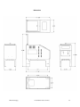
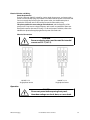
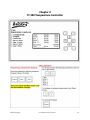
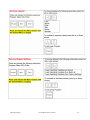
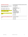
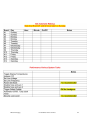
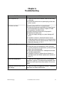
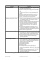
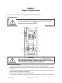
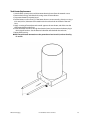
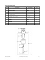
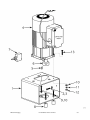
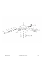
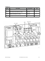
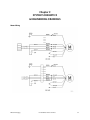
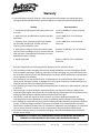
1
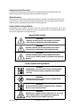
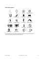
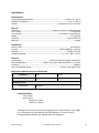
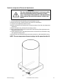
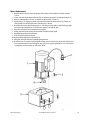
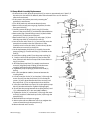
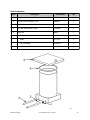
Cal
lusat8006427876
D215Ma
nua
l
1960010D215
Rev
.
A 22410
ASTRO PACKAGI
NG
3845E.Mi
r
al
omaAv
e,Uni
t“
A”
Anahei
m,CA92806
8006427876/7145721094
FAX7145721943
www.
ASTROPACKAGI
NG.
com
SAFETY PRECAUTIONS
GENERAL CONSIDERATIONS
SERVICING EQUIPMENT
1. Read and follow these instructions. Failure to do
this could result in severe personal injury or death.
1. Only trained personnel are to operate and service
equipment.
2. Additional safety instructions and/or symbols are
located throughout this manual. They serve to warn
maintenance personnel and operators about
potentially hazardous situations.
2. Never service equipment while it is in motion.
3. Inspect the machine for unsafe conditions daily
and replace all worn or defective parts.
3. Shut off the equipment and lock out all input
power and air supply at their sources before
attempting any maintenance.
4. Follow the maintenance and service instructions in
the manual.
4. Keep work area uncluttered and well lit.
SIGNS
5. All covers and guards must be in place before
operating this equipment.
For precautions and definitions of safety symbols,
refer to Safety Chapter of the service manual.
1. Read and obey all of the warning labels, signs and
caution statements on the equipment.
2. Do not remove or deface any of the warning labels,
signs, and caution statements on the equipment.
3. Replace any warning labels, signs, and caution
statements which have been removed or defaced.
Replacements are available.
ADDITIONAL CONSIDERATIONS
1. To ensure proper operation of the equipment, use
specified electrical and/or air supply sources.
2. Do not attempt to alter the design of the
equipment unless written approval is received from
our factory.
3. Keep all manuals readily accessible at all times and
refer to it often for the best performance from your
equipment.
TABLE OF CONTENTS
Chapter 1 Safety Precautions
Chapter - Page #
Chapter 2 Description & Specifications
Description ............................................................................................................................................
2-1
Features ................................................................................................................................................... 2 - 1
Specifications ....................................................................................................................................... 2 - 2
Motor Speed, Adhesive Pressure, and Flow Rate ..................................................................... 2 - 2
Dimensions ............................................................................................................................................ 2 - 3
Chapter 3 Installation & Start Up
Installation .............................................................................................................................................
3-1
Component Installation ....................................................................................................................
3-1
Start-Up ................................................................................................................................................... 3 - 3
Adding Adhesive .................................................................................................................................
3-3
Changing Adhesive Formula ........................................................................................................... 3 - 3
Adjusting the Flow Control Valve ..................................................................................................
3-4
Storage & Disposal of the Application System .........................................................................
3-5
Chapter 4 TC 500 Temperature Controller Set-Up
Programming Temperature Set-points ........................................................................................ 4 - 1
Set Offset Temperature .....................................................................................................................
4-2
Set Automatic Wakeup ......................................................................................................................
4-2
Set Clock Calendar ..............................................................................................................................
4-3
Save and Register Setting ................................................................................................................
4-3
Display/Set Audit Variables .............................................................................................................. 4 - 4
Performance Various System Tasks ...............................................................................................
4-5
Security Lock Level .............................................................................................................................. 4 - 6
Chapter 5 Preventive Maintenance
Maintenance .........................................................................................................................................
5-1
Preventive Maintenance ...................................................................................................................
5-1
Chapter 6 Troubleshooting
General Troubleshooting .................................................................................................................. 6 - 1
Tank does not heat .............................................................................................................................. 6 - 1
Zone Over-temperature .................................................................................................................... 6 - 1
Applicator and Hose Heat Slowly ..................................................................................................
6-1
Motor does not turn ...........................................................................................................................
6-2
Applicator and Hose Fail to Heat ...................................................................................................
6-2
Adhesive Output Levels ....................................................................................................................
6-2
Chapter 7 Repair & Replacement
Hose Replacement ..............................................................................................................................
7-1
Tank Heater Replacement ................................................................................................................
7-3
Tank RTD Sensor Replacement ....................................................................................................... 7 - 4
Tank Over-temperature Thermostat Replacement .................................................................
7-5
Motor Replacement ............................................................................................................................ 7 - 6
Pump Filter Installation & Replacement ...................................................................................... 7 - 7
V4 Pump & Flow Control Block Replacement ............................................................................ 7 - 8
V4 Pump Block Assembly Replacement ...................................................................................... 7 - 9
Chapter 8 Component Illustration and Bill of Materials
Recommended Spare Parts .............................................................................................................
8-1
Tank Components ...............................................................................................................................
8-2
Bushing and Assembly Shaft .......................................................................................................... 8 - 3
Motor Group & Mounting Hardware ............................................................................................
8-4
Pump/Motor Assemblies ..................................................................................................................
8-6
Pump Group ..........................................................................................................................................
8-8
Flow Control Group ............................................................................................................................
8 - 10
TC500 Circuit Board ............................................................................................................................
8 - 12
TC500 Fuses ...........................................................................................................................................
8 - 13
Chapter 9 Component Illustrations
Motor Wiring Diagram........................................................................................................................................
9-1
Wiring Diagram 120 V Unit ...............................................................................................................................
9-2
Wiring Diagram 240 V Unit ...............................................................................................................................
9-3
Chapter 1
Safety Precautions
This manual contains important safety information and instructions. Failure to comply with these
instructions can result in death, injury or permanent damage to this equipment and will void the
warranty.
Intended Use
This equipment is designed for use with standard adhesive and sealant materials with flash points
above 232 °C (450 °F). Use of flammable material or material not compatible with the
specifications of this equipment can cause injury to operator and damage to equipment.
The manufacturer has designed this equipment for safe operation. Specified models are in
compliance with EN 60204-1:1997. However, heated thermoplastics and other hot melt materials
are dangerous and care must be exercised to ensure operational safety. Handling must be in
accordance with hot melt manufacturer specifications. Never exceed the maximum application
temperature recommended by the adhesive manufacturer.
Dispose of hot melt properly. Refer to the Materials Safety Data Sheet (MSDS) of the hot melt for
recommended disposal methods.
Personal Safety
Wear the following protection when working on or around this
equipment:
Always wear heat resistant gloves rated to 205 °C (400 °F) and allow all
system temperatures to stabilize below 193 °C (380 °F) before servicing.
Properly ventilate equipment according to MSDS of equipment. Trained
operators and service technicians should be aware of exposed surfaces of
the unit that cannot be practically safeguarded. These exposed surfaces
may be hot and take time to cool after the unit has been operating.
Keep parts of the body away from rotating parts. Do not wear loose Safety
Gloves, articles of clothing when operating or servicing units with rotating
parts. Remove wristwatches, rings, necklaces, or other jewelry and cover or
pin up long hair before performing any work on or with the unit.
Trained operators may perform only external equipment adjustments.
Trained service technicians must perform internal adjustments and service.
Electrical Safety
Determine voltage of this equipment before installation and confirm compatibility with available
power. Equipment must be connected to a properly grounded circuit and installed in accordance
with all applicable electrical codes. Ground fault protection must be provided in supply circuitry at
site installation. Models designed to EN60204-1: 1997 require power cords be approved to a
harmonized (HAR) standard and rated for 70 °C (158 °F). A HAR approved Type B plug and strain
relief for power cord are required to meet standard IEC 309. Power conducting wires must be
2
2
nominal 5.3 mm (10 AWG) maximum and nominal 2.1 mm (14 AWG) minimum.
©Astro Packaging
D2-15 Manual-19600-10-D215
1-1
Emergency Power Disconnect
In the event of a malfunction, turn off power to the equipment at the power off switch and
remove source power to the system at the nearest main disconnect.
Follow Directions
Read the product manual thoroughly before installation, operation or maintenance. Failure to do
so can result in a serious accident or equipment malfunction. The manufacturer will not be held
liable for injuries or damage caused by misuse of this equipment.
Safety Symbols and Signal Words
The following safety symbols and signal words are used throughout the manual and on the
product to alert the reader and operator to personal safety hazards or to identify conditions that
may result in equipment or property damage.
General Safety Symbols
CAUTION:
Indicates a hazard, which, if not avoided, can result in
minor injury, or equipment and property damage.
WARNING:
Indicates a hazard, which if not avoided, can result in
serious injury, or equipment and property damage.
DANGER:
Indicates a hazard, which, if not avoided, will result in
serious injury, including death, or equipment and property
damage.
Specific Symbols and Signal Words
DANGER:
High Voltage. Can cause serious injury, including death.
Disconnect electrical power at external source before
servicing.
WARNING:
Hot Surface. Can cause serious injury, including death.
Disconnect electrical power
WARNING:
Disconnect electrical power at external source. Failure to
do so can cause electrical shock.
WARNING:
High Pressure. System contents under pressure. Can cause
serious injury and burns or equipment and property
damage. Relieve pressure before servicing.
©Astro Packaging
D2-15 Manual-19600-10-D215
1-2
Other Product Symbols
On
Off
Ground
Protective Earth
Tank
Heated Hose
Applicator
Pump Motor
Set Temp
Standby Temp
Over-temp
Adhesive Flow
Tank Heater
Alarm
Actual Temp
Source Power
Manual Task
Input
Output
Valve Group
The manufacturer reserves the right to make design changes for product improvement. This
manual may not reflect all details of these improvements.
©Astro Packaging
D2-15 Manual-19600-10-D215
1-3
Chapter 2
Description and Specifications
Description
The D215 Hot Melt Unit is a light-duty to medium-duty machine used for melting and pumping a
variety of materials. The melt unit consists of a heated melt tank and a motor-driven, positive
displacement V4 series gear pump. The melt unit is compatible with a variety of Astro Packaging
pattern generators and head drivers.
The D215 Hot Melt Unit is all-electric and accepts standard forms of adhesive. The unit is equipped
with a flow control valve for fluid pressure and flow regulation. The melt unit has a 6.82 kg (15 lb.)
tank capacity, and supports 1 or 2 automatic or manual applicators and hoses.
All zone temperatures range from 4 °C (40 °F) to 232 °C (450 °F), adjustable by a TC500
Temperature Controller. An integral melt grid is standard.
Electrical power to the melt unit is controlled by a power-disconnect circuit breaker located on
the front end of the melt unit.
Features
• The solid-state Temperature Controller uses Resistance Temperature Detector (PT 100 RTD)
sensors to sample and regulate temperatures in the tank, hoses and applicators.
• Circuit breakers and fuses protect the entire system from overload.
• A tank-mounted over-temperature thermostat switches the system power off in the event of a
tank controller failure.
• A circuit breaker protects the pump motor by switching the motor off should a stall or an
overload condition occur.
• TC500 Temperature Controller protects pump/motor from starting before the material in
system is Run-Ready.
• TC500 Temperature Controller provides a 7-Day Scheduler to Automatically turn the system On
and Off once per day.
•TC500 Temperature Controller provides over-temperature protection to all zones and will shut
down the main circuit breaker if a temperature zone is over temperature.
©Astro Packaging
D2-15 Manual-19600-10-D215
2-1
Specifications
Environmental:
Storage/Shipping Temperature ............................................................................................. 0-60° C (32 - 140° F)
Ambient Air Temperature ......................................................................................................... 5 - 40° C (41-104° F)
Altitude .................................................................................................................. Sea level up to 2 km (1.24 miles)
Physical:
Dimension ............................................................................................. dimensional layouts on following pages
Tank Capacity ............................................................................................................................................ 6.8 kg (15 lb.)
Hose Capacity ........................................................................................................ 2 automatic or 2 manual hoses
Weight ....................................................................................................................................................... 35.4 kg (78 lb.)
Pump Size ........................................................................................................................................ V4-675: (0.675 CID)
Melt Grid ................................................................................................................................................................ Integral
Performance:
Warm-up Time ........................................................................................................................................ 30-45 minutes
Viscosity ..................................................................................................................... 70 PaS (70,000 cps) maximum
Melt Rate ......................................................................................................................................... 6.8 kg/hr (15 lb./hr)
Temperature Range ..................................................................................................... 4° C - 232° C (40° F - 450° F)
Electrical:
Input Voltage ................................................................................120 VAC single-phase, 240 VAC single-phase
Power Requirements ............................................. 120 VAC L1/N G, 20 A, 50/60 Hz,240 VAC L1, L2, G 20 A
Frequency ........................................................................................................................................................... 50/60 Hz
Main Circuit Breaker Rating ................................................................................... 120 VAC: 20 A, 240 VAC: 20 A
Motor Speed, Adhesive Pressure, and Flow Rate
Frequency
Motor Speed
60 Hz
50 Hz
86 rpm
70 rpm
Adhesive Pressure
V4-675 Pump
100-800 PSI
Sample Flow Rates*
V4-675 Pump
60 Hz, 86 rpm
50 kg/hr @ 17.24 bar
(110 lb./hr @ 250 psi)
*These figures are based on standard, packaging grade hot melt materials at 1 PaS (1,000
cps). These figures vary with adhesive and tank temperature. Consult your Astro
Packaging representative for non-standard material requirements.
©Astro Packaging
D2-15 Manual-19600-10-D215
2-2
Dimensions
©Astro Packaging
D2-15 Manual-19600-10-D215
2-3
Chapter 3
Installation and Start-Up
Installation
Set-Up
1.Remove all packaging material from around the melt unit.
2.Carefully lift the melt unit out of the box.
3.Unpack the binder containing the product manuals, electrical schematics, and warranty
information. Retain the binder for future reference.
4.Unscrew the 4 screws from the plywood board base; remove and discard the plywood.
5.Carefully inspect all packing material for separately wrapped items.
6.Position the melt unit for easy access to the control panel and convenient servicing.
7.Using the base mounting holes, bolt the melt unit down to a durable mounting surface in
accordance with the dimensions listed in Section 3: Specifications to prevent accidental
upset and possible injury.
8.Tighten all screws before startup and after the melt unit experiences excessive vibration.
Component Installation
Automatic Systems
Hoses
Hoses are normally installed on an automatic melt unit at the factory with no user
installation required. If they are not installed, see Hose Replacement. Refer to the
enclosed Heated Supply Hoses product manual (Astro Packaging P/N 19600-24) for
complete installation and service information.
Automatic Applicators
Automatic applicators may be attached to hoses or packaged separately. If they are not
installed, proceed as follows:
1. With the system power off, attach the hose output electrical connector to the
applicator. Heat the fluid fittings on the applicator and the output end of the hose by
attaching the electrical connector and applying power for 3 – 5 minutes, or until the
hose fitting will rotate.
2. Connect the output end of the hose to the adhesive input fitting on the applicator.
3. When the system reaches operating temperature, retighten all the adhesive
connections. Pressurize and check for leaks.
Refer to the applicator product manual for installation and service information.
©Astro Packaging
D2-15 Manual-19600-10-D215
3-1
Electrical Circuits and Wiring
Power Requirements
The D215 melt unit 120 VAC is wired for 2-wire, single-phase power, and comes with a
power-cord and 20 Amp plug. The 240 VAC unit comes with the power cord but the end
user must supply the power plug for their power outlet. An identification plate is
attached to each melt unit on the outside, rear panel of the tank housing.
This plate specifies the exact voltage of the melt unit, and the frequency of the
pump motor. Pump motor voltage, frequency and current are specified on the motor
data plate located on the motor housing. For safe and proper installation, refer to the
identification plate before applying electrical power to the melt unit.
Electrical Connections
CAUTION:
Power conducting wires must be rated for intended
current and 75° C (167° F).
120 VAC L1/N
Single-phase service
240 VAC L1, L2
Single-phase service
Operation
DANGER:
Disconnect power before opening front panel.
Hazardous voltage can shock, burn, or cause death.
©Astro Packaging
D2-15 Manual-19600-10-D215
3-2
Start-Up
1. Become familiar with the temperature controller information in the D2-15 manual.
2. Install the melt unit.
3. Fill the tank with hot melt material to 38 mm (1.5 in.) from the top.
4. Turn the unit on, and allow for 30 minutes of warm-up time.
5. Set the tank, hose and applicator temperatures to the desired settings. Lower settings will
increase the material pot life.
6. Set the tank temperature as low as possible for each application. Certain materials degrade
over time due to oxidation.
7. To prevent stalling the motor, adjust the flow control valve counterclockwise to minimize
pressure and lower flow rate.
*NOTE: the pump motor will not run until the TC500 has green ready LED.
Adding Adhesive
The adhesive level should be maintained at 13 mm to 100 mm (1/2” to 4”) from the top of the tank. Where
applications demand a high output volume of adhesive, add small amounts of adhesive frequently.
ADDING LARGE AMOUNTS OF ADHESIVE TO AN ALMOST EMPTY TANK WILL LOWER THE TEMPERATURE OF
THE ADHESIVE IN THE TANK AND MAY CAUSE THE MELT UNIT TO FALL BELOW ITS READY SET-POINT.
Changing the Adhesive Formula
If a different adhesive formulation from the one being currently used is needed, the system will have to be
flushed if the two formulations are incompatible. See Chapter 6 of this manual for the proper flushing
procedure. When in doubt about adhesive compatibility, flush your system.
©Astro Packaging
D2-15 Manual-19600-10-D215
3-3
Flow Adjustments
WARNING:
Contents at high temperature and pressure. Remove
pressure before opening filter or drain valve to prevent
accidental system pressurization or firing. Do not touch hot
surfaces. Failure to follow these instructions may result in
severe burns.
CAUTION:
For maximum performance and motor life, do not allow
the pump motor to stall. A prolonged stall condition
will call condition will cause the motor go into thermal
overload.
Flow Control Valve
An adjustable, pressure-regulating device is mounted on the pump under the melt unit chassis.
See the illustration below.
• Adjust the flow control by turning the provided 1/4 inch allen wrench on the left side
of the melt unit.
• To increase the pressure, turn clockwise.
• To decrease the pressure, turn counterclockwise.
• To achieve the minimum pressure and the lowest flow rate, turn the knob fully
counterclockwise. Gradually turn the knob clockwise until the desired pressure and
flow rate are achieved.
©Astro Packaging
D2-15 Manual-19600-10-D215
3-4
Storage and Disposal of the D2-15 Application System
Temporary Storage of the Unit
1. Flush the adhesive application system with flushing fluid (PN RB-5), following the instructions detailed
in Chapter 6 of this manual.
2. Clean or replace both the output filter and the tank, following instructions detailed in Chapter 6.
3. Shut OFF all pressure and power sources.
4. Remove all residual adhesive and wipe components clean.
5. Remove all power supply cables.
6. Pack the unit in a corrosion-proof manner.
7. Store the unit in such a way that it is protected from damage.
Disposal of the Unit
1. Shut OFF all pressure and power sources.
2. Remove all residual adhesive.
3. Remove all adhesive supply hoses and all power supply cables.
4. Dismantle all components and sort into mechanical and electrical components.
5. Arrange for all components to be recycled.
©Astro Packaging
D2-15 Manual-19600-10-D215
3-5
Chapter 4
TC 500 Temperature Controller
©Astro Packaging
D2-15 Manual-19600-10-D215
4-1
©Astro Packaging
D2-15 Manual-19600-10-D215
4-2
©Astro Packaging
D2-15 Manual-19600-10-D215
4-3
©Astro Packaging
D2-15 Manual-19600-10-D215
4-4
©Astro Packaging
D2-15 Manual-19600-10-D215
4-5
©Astro Packaging
D2-15 Manual-19600-10-D215
4-6
©Astro Packaging
D2-15 Manual-19600-10-D215
4-7
Chapter 5
Preventive Maintenance
Maintenance
WARNING:
Hot melt materials can cause severe burns resulting in disfigurement or blindness.
Follow these precautions before beginning any maintenance:
• Wear protective clothing, safety goggles, and safety gloves.
• Turn pump motor switch to the off position.
• Depressurize applicator(s) by triggering.
• Unless stated otherwise, always allow melt unit to cool before
beginning any maintenance.
• Disconnect hose electrical connector when hose fittings are
disconnected and power is off.
CAUTION:
To prevent damage to components (hose fittings, etc.), heat part(s) being
serviced to approximately 121 °C (250°F) prior to dismantling, assembling,
or adjusting. Heat parts by applying power to the unit using a hand held
hot air gun or placing parts on a hot plate. Failure to do this will result in
stripped threads and ruining both parts and tools.
CAUTION:
To avoid arcing of electrical contacts and possible failure of components,
do not connect electrical connectors when the hose power switch is on.
Preventive Maintenance
Procedure
Daily
Monthly
As Required*
Purge tank and hose(s).
X
X
Inspect hose(s). Verify hose(s) properly
supported. Minimum bend radius is
20.32 cm (8 in.) when hot.
X
Check temperatures. Adjust
temperatures according to Temperature
Controller manual.
X
Check for foreign material in tank
X
Wipe off excess hot melt from cover.
X
Check for leaks.
X
Clear applicator nozzles.
X
Inspect/Replace Pump Filter
©Astro Packaging
X
D2-15 Manual-19600-10-D215
X
5-1
Chapter 6
Troubleshooting
Problem
Solutions
Does not power up.
1. Check the main circuit breaker. Refer to the wiring
schematic.
2. Inspired the power wires or power plug at the main
power source.
Tank does not heat.
1. Check 8 Amp tank fuses on power board.
2. Check the temperature controller for Power On and
Tank Temperature Set. Refer to Chapter 4 TC500
Temperature Controller Guide.
3. Inspect the power connections for proper fit.
4. Check for any faulty wires.
5. Check the supply voltage, or system damage will
occur.
6. If problem still exists, check each heater with an
amperage probe (system power on) or an ohmmeter
(system power off, wires disconnected). Refer to the
electrical schematics in Ch. 9.
Tank heats slowly.
1. Check 8 Amp tank fuses on power board.
2. Check the status of components with a voltmeter
(system powered) or an ohmmeter (system powered
down, wires disconnected).
3. Adjust the tank temperature. Inadequate tank heat
can affect performance.
4. If problem still exists, replace the tank heaters as
specified under tank heater replacement section on
page 7-3.
Zone over-temperature.
1. Check the zone temperature when an over-temp
condition is present. The temperature controller shuts
off power to all zones if one zone reaches 20° over setpoint.
Applicator and hose heat slowly,
low voltage.
1. Adjust the hose and applicator settings. Inadequate
heat levels can affect performance.
©Astro Packaging
D2-15 Manual-19600-10-D215
6-1
Problem
Solutions
Motor does not turn.
1. Check to see if applicator or hose is programmed on
the TC500. See TC500 manual.
2. Check to see if the green ready light on the TC500 is
ON.
3. Check to see if melt unit is up to temperature (all
zones).
4. Check to see if pump circuit breaker switch is On.
5. Check to verify there is no obstruction in pump.
6. Check 5 Amp motor fuse on power board.
Applicator and hose fail to heat.
1. Check the incoming hose electrical connector to see
if it is properly installed. The connector wire pins
may be misaligned or loose.
2. If there is no change, disconnect the incoming hose
electrical connector, and check the hose heater
resistance value with an ohmmeter. If the hose
heater fails, replace the hose. See Heated Hose
Manual.
3. Determine if the applicator is heating by using a
pyrometer or temperature sensing device. Do not
touch applicator by hand to determine temperature.
4. Check 6.3A fuse on power board.
Adhesive output is too high.
1. Decrease the system fluid pressure with the flow
control valve (6-2). If there is no change, remove the
nozzle and replace it with a smaller orifice nozzle.
2. Decrease the hose temperature by 4-10°C (25-50°F).
If there is no change, consult Astro Packaging
regarding application.
Adhesive output is too low.
1. Increase the system fluid pressure, taking great care
not to stall the motor, by adjusting the flow control
valve. If there is no change, remove the nozzle and
replace it with a larger-orifice nozzle.
2. Clean applicator nozzle.
3. Clean/replace pump filter.
4. Purge the system.
5. Hot melt formulations tend to be a factor in
previously listed problems. Refer to Ch. 3 for start-up
cautions.
6. Increase the hose temperature by 4-10°C (25-50°F).
If there is no change, consult Astro Packaging
regarding the application.
Contact Astro Packaging Technical Services department for assistance at (800) 642-7876
©Astro Packaging
D2-15 Manual-19600-10-D215
6-2
Chapter 7
Repair & Replacement
Refer to Parts List, in Chapter 8, for all replacement parts listed in this section.
Hose Replacement
CAUTION:
For safe and proper hose replacement, verify that all material in
melt tank has completely solidified.
CAUTION:
The illustration above is for reference only. DO NOT TURN THE
MELT UNIT UPSIDE DOWN. Failure to comply with this caution can
result in injury and/or damage to the equipment.
Removal of an Existing Hose
1. Switch the system power off, and allow the hot melt in the tank to completely solidify.
2. Switch the system on for 5 minutes to allow the fittings to warm, or heat the fittings with a handheld
hot air gun.
3. Switch the system power off, and disconnect the melt unit electrical power from the external source.
4. Disconnect the hose electrical connector [4].
5. Remove the screws from the hose-mounting block [5].
6. Loosen the hose JIC fitting [1], and remove the hose from the fitting [2] on the flow control block [3].
©Astro Packaging
D2-15 Manual-19600-10-D215
7-1
Installation of a New Hose
1. Never flex a hose when it is cold. Hoses have a minimum bend radius of 20.32 cm (8 in.)
when hot.
2. Further flexing will cause permanent damage.
3. Switch off the system power, and disconnect the melt unit electrical power from the
external source.
4. Heat the hose JIC fittings [1] before adjusting, or damage may result. New or clean hose
fittings may not require heating.
5. Install the hoses onto the melt unit by tilting the unit back until the underside is accessible.
6. Support the melt unit with a block on the back of the housing so that hot melt does not
spill. Do not turn the melt unit upside down.
7. Support the hose to prevent excessive flexing. Do not support the hose in a way which may
add to its thermal insulating characteristics, or overheating will result. Failure to properly
support the hose will result in premature failure.
Install the hose as follows:
1. Loosely connect the hose JIC swivel fitting [1] to the fitting [2] on the flow control block or
hose manifold [3].
2. Fasten the hose support block [5] to the chassis.
3. Tighten the JIC swivel fitting [1].
4. Attach the hose electrical connector [4]
5. Tuck the hose electrical connector [4] under the melt unit.
6. Position and support the hose before using.
7. After heating the hose, tighten the JIC swivel fitting [1].
©Astro Packaging
D2-15 Manual-19600-10-D215
7-2
Tank Heater Replacement
1. Switch off the system power, and disconnect electrical power from the external source.
2. Remove the housing, and retain the housing screws for reinstallation.
3. Disconnect heater from power board
4. Pull the heater out of its bore [1]. If the heater does not come out easily, drive it out using a
6.35 mm (0.25 in.) diameter rod inserted into the knockout holes in the back of the tank
base.
5. Apply a coating of heat release and transfer agent to the new heater, and slide it into the
tank heater bore from the front.
6. Route the heater lead wires through the electrical panel, and reconnect the heater plug in
their original locations. See the electrical schematic included with the melt unit.
7. Reinstall the housing.
NOTE: The tank heater connections at the power board are J6 and J7, and are fused by
F1 and F2.
©Astro Packaging
D2-15 Manual-19600-10-D215
7-3
Tank RTD Sensor Replacement
1. Switch off the system power, and disconnect electrical power from the external source.
2. Remove the housing, and retain the housing screws for reinstallation.
3. Locate the RTD sensor [2] in its bore on the tank base.
4. Remove the failed sensor from the bore located at the tank base. Note the wire routing for
installation.
NOTE: The sensor plugs into the CPU board at J2.
5. Coat the RTD sensor lightly with heat sink compound.
6. Slide the new RTD sensor [2] into its bore.
7. Route the RTD lead wires in their original locations, as noted in Step 4.
8. Reinstall the housing.
©Astro Packaging
D2-15 Manual-19600-10-D215
7-4
Tank Over-temperature Thermostat Replacement
WARNING:
The over-temperature thermostat is a necessary safety
device for preventing runaway heating on all melt
units. Do not bypass this protection. Runaway heating
of the tank can cause hot melt materials to burst into
flames.
1. Disconnect the melt unit electrical power at the external source.
2. Remove the housing, and retain the housing screws for reinstallation.
3. Locate the over-temperature thermostat [3].
4. Remove and retain the mounting screws and wire connectors from the over-temperature
thermostat.
5. Remove the thermostat, and clean the mounting surface.
6. Apply a small amount of heat sink compound on the back side of the replacement overtemperature thermostat.
7. Position the thermostat in the appropriate location on the tank base, and attach it using
the original mounting screws.
8. Reconnect the over-temperature thermostat wire connectors, and reinstall the housing.
NOTE: The over-temperature thermostat plugs into the power board at J8.
©Astro Packaging
D2-15 Manual-19600-10-D215
7-5
Motor Replacement
1. Remove electrical power from the system at the main circuit breaker and at the external
source.
2. Locate and remove the electrical cord [2] that connects the motor [1] with the control box.
2
3. Remove and retain the 4 screws [3] at the base plate of the motor [1].
4. Pull the motor [1] slightly out, then down and away from the motor mount [5]. The motor
shaft coupler [4] will clear the motor mount hole, as shown.
5. Install the new motor by following steps 2 - 4 in reverse order. Refer to the following pages
for the wiring configurations for each motor type (44, 70 and 86 rpm).
6. Open the control box cover and the control panel.
7. Locate and remove the pump circuit breaker from the control panel.
8. Install the new pump circuit breaker.
9. Close the control panel and cover.
10. Restore electrical power to the melt unit.
11. Allow the melt unit to heat to operating temperature.
12. Test the motor for correct rotation. While looking down on the motor, the motor shaft should
turn counterclockwise. The cooling fan may spin in the opposing direction, so it is important
to judge the correct rotation by the motor shaft.
©Astro Packaging
D2-15 Manual-19600-10-D215
7-6
Pump Filter Installation and Replacement
The pump filter is installed in the flow control block. Refer to the figure below for installation and
replacement of the filter element.
WARNING:
Contents at high temperature and pressure. Remove
pressure before opening filter or drain valve to prevent
accidental discharge of system pressure. Do not touch hot
surfaces. Failure to follow these instructions may result in
severe burns.
1. Bring the melt unit to operating temperature.
2. Switch off the pump motor.
3. Actuate the applicator several times to relieve all pressure in the system.
4. Place a disposable container below the filter access area to catch all the adhesive spillage or
run off.
5. Slowly remove the cap [1], fitting [2] and o-ring [3] to release any residual pressure trapped
in the flow control block [5].
6. Remove the filter [4]. It is recommended that the filter be replaced and not cleaned for
reuse.
7. Carefully switch the pump motor on for approximately 1 - 2 seconds to cause a small
amount of adhesive to flush the filter chamber. Clean the filter chamber of all foreign
material. Repeat if necessary.
8. Insert the new filter [4] into the flow control block [5].
9. Inspect the o-ring [3], and replace it if it is damaged.
10. Install the fitting [2], o-ring [3] and cap [1] securely into the flow control block [5]
©Astro Packaging
D2-15 Manual-19600-10-D215
7-7
V4 Pump and Flow Control Block Replacement
WARNING:
Contents at high temperature and pressure. Remove pressure before opening
filter or drain valve to prevent accidental discharge of system pressure. Do not
touch hot surfaces. Failure to follow these instructions may result in severe burns.
1. If melt unit is cold, allow to heat for approximately 5 minutes.
2. Depressurize the system by manually actuating the applicator(s).
3. Remove electrical power from the system at the main circuit breaker and at the external source.
4. Disconnect the hose fluid connection(s) from the flow control block [5]. Disconnect the hose
electrical connection(s) from the bottom of the control box. Set the hose(s) aside.
5. Remove the 4 screws, flat washers and lock washers [2, 3, 4] holding the flow control block [5].
6. Remove the flow control block [5], and set it aside. Do not lay the flow control block flat on any
surface, it may glue itself to the surface.
7. Remove and discard the existing pump [10], gasket [11], wear plate
[8], and pump o-ring [9].
8. Reassemble the pump as follows:
NOTE: V4 pump is shipped with bolts and nuts [15] holding
pump [10] and wear plate [8] together.
a. Remove and discard the bolts and nuts [15] holding the new
pump [10] and wear plate [8] together.
b. Place the 4 screws, flat washers and lock washers [2, 3, 4]
into the flow control block [5].
c. Cover the new pump o-ring [9] with silicone grease, and
place it into the groove in the pump body.
d. Coat and insert the wear plate o-ring [7] into the groove in
the pump wear plate [8]. Place the pump body [10] onto the
wear plate [8], ensuring not to pinch the o-ring [7].
e. Place the new pump [10] and wear plate [8] into the flow
control block [5]. Align the assembly with the screws, flat
washers and lock washers [2, 3, 4] so that the bushing
assembly [14] faces away from you and the flow control
valve faces to the right.
f. Place new gasket [11] on pump [10]. No sealants needed.
9. Align the pump shaft slot on the end of the shaft [13] with the tab
atop the pump [10].
10. Slide the pump assembly into the pump block [12] and tighten the
screws, flat washers and lock washers [2, 3, 4] in a crisscross
fashion.
11. Reconnect hose(s) fluid and electrical connections, and reapply
electrical power to the melt unit.
12. With the pump switch off, allow the melt unit to heat to operating
temperature.
13. Retighten pump screws to 5.65 – 8.47 N-m (50 – 75 Ibs.-in.).
14. Adjust the adhesive pressure by turning the flow control knob [1].
Refer to Section 4.2 Adjustments.
15. Test the melt unit, adjust the pressure and check for leaks.
16. Return the melt unit to service.
©Astro Packaging
D2-15 Manual-19600-10-D215
7-8
V4 Pump Block Assembly Replacement
1. If the melt unit is cold, allow the pump block [3] to warm to approximately 90 °C (200 °F). If
the melt unit is hot and full of adhesive, either allow the melt unit to cool or drain the
adhesive from the tank.
8
2. If the system is hot, relieve pressure by actuating the
applicator(s) several times.
3. Turn off the melt unit, and remove electrical power.
4. Remove all hoses and pressure gauge, if present, from the
flow control block [1].
5. Carefully remove the plug [14] and o-ring [15] from the
bottom of the pump block [3], and drain the melted adhesive.
6. Remove the long socket head cap screws [16] that hold the
pump block [3] to the bottom of the tank.
7. Remove the 4 bolts [11], washers [12] and spacers [13] that
hold the pump block [3] to the motor mount [8].
8. Once all 4 bolts and 4 screws [11, 16] are removed, move the
pump block assembly to the rear of the chassis. If the
assembly resists loosen the 2 bolts [9] and washers [10] that
hold the motor mount [8] to the chassis.
9. On the replacement pump block [3] assembly; loosen the
pump coupling [6]. Ensure that the key [5] is installed on the
shaft [4]
10. Insert the coupling spider [7] into the pump coupling [6].
11. Coat the surface of the pump block [3] that contacts the
base of the tank with heat sink compound. Ensure that the oring [2] is in place.
12. Place the new pump block [3] assembly into the motor
mount [8]. Align the pump coupling [6] with the motor
coupling, and slide the new assembly into place.
13. Tighten the pump coupling [6] onto the new shaft [4],
leaving
0.762 -1.016 mm (0.030 - 0.040 in.) clearance between the
coupling halves.
14. Loosely insert the 4 bolts [11] and washers [12] through the
motor mount [8] into the pump block [3]. Ensure that the
spacers [13] are in place between the motor mount [8] and
the pump block. [3]. Do not tighten the bolts at this time.
15. Insert the socket head cap screws [16] up through the pump
block [3] into the tank bottom. Tighten only finger tight.
16. Ensure that the spacing between the coupling halves [6 and
17] is still between 0.762 -1.016 mm (0.030 - 0.040 in.).
17. Tighten the 4 bolts [11] and washers [12] through the motor
mount [8] and the 4 socket head cap screws [16] through the
pump block [3].
18. Reinstall the hoses and pressure gauge.
19. Warm up the melt unit. When the unit is hot, retighten the
screws mounted through the pump block [3].
20. Return the melt unit to service.
©Astro Packaging
D2-15 Manual-19600-10-D215
7-9
Chapter 8
Component Illustration and Bill of Materials
Recommended Spare Parts
Part Number
Description
Qty
12014-8B
Fuse, 8 amp, 5 X 20mm
2
12014-5
Fuse, 5 amp, 5 X 20mm
2
939683
Fuse, 6.5 amp, 5 X 20mm
2
10760-50
Pump filter
1
D200109
Assembly, Tank RTD, 100 ohm
1
D200111
Assembly, Over-temp Thermostat, 475°
1
©Astro Packaging
D2-15 Manual-19600-10-D215
8-1
Tank Components
Item
Description
1
Tank, Over-temperature Thermostat, 232°C (475°F)
D200111
1
2
Kit, Sensor, RTD 100 ohm, Tank
D200109
1
3
Kit, Tank Heater, 120 V, 750 W
D212600
2
3
Kit, Tank Heater, 240 V, 750 W
D212600-2
2
4
Tank Seal
70020
1
5
Tank Lid Assembly
79283-15
1
Knob
14517-99
1
Lid, Outer Black
70586-462
1
Lid, Inner, Gold Zinc
70586-463
1
©Astro Packaging
Part Number
D2-15 Manual-19600-10-D215
Qty
8-2
Bushing/Assembly Shaft
Item
Description
Part Number
Qty
1
Bearing and Shaft Assembly (Items 2-9)
79361
1
2*
Pump Drive Shaft
70604
1
3
Key, Machine, 1/8 in. Square x 0.5 in. Long
14475-1
1
4
Bushing Assembly
70827-71
1
5
Coupling, 9/16 in., 1/8 Key
18425-4G
1
6
Spider, Bronze
18425-7C
1
7*
Retainer
70601
1
8*
Shaft Seal
10483
1
9
Socket Head Cap Screw, 1/4-20 X 1.75 in.
14431-GDO
2
* To replace shaft only, order items 2,7,8.
©Astro Packaging
D2-15 Manual-19600-10-D215
8-3
Motor Group and Mounting Hardware
Item
Description
Part Number
Qty
1
Motor Mount
70827-87
1
2
Lock Washer, 3/8
14452-KA
4
3
Bolt, Hex, 3/8-16 X 2-1/4 in.
14433-KAQ
4
4
Motor Group, 86 rpm 120 VAC
D279424
1
4
Motor Group, 86 rpm 240 VAC
D279424-2
1
5
Key, Motor Shaft, 86 rpm 3/16 in. sq. X 1.12 in. lg.
14475-8
1
6
Coupler, 1/2 in., 86 rpm Motor 3/16 in. key
18425-3
1
7
Circuit Breaker, 86 rpm, 2.5A, 120 VAC
12055B-25
1
7
Circuit Breaker, 86 rpm, 1.5A, 240 VAC
12055A-15
1
8
Spacer, 86, 5/8 in. OD, 3/4 in. long
70827-84-2
4
9
Bolt, Hex, 3/8-16 X 1.5 in., 86 rpm motor
14433-KAN
4
10
Lock Washer, .25 in. ID
14451-GA
4
11
Flat Washer, 1/2 in.
14456-GA
4
12
Nut 1/4-20
14441-GA
4
13
Screw, Hex, 1/4-20 X 1 in.
14433-GAK
4
Capacitor, 86 rpm motor (not shown)
18416-10
1
©Astro Packaging
D2-15 Manual-19600-10-D215
8-4
©Astro Packaging
D2-15 Manual-19600-10-D215
8-5
Pump/Motor Assemblies
Item
Description
Part Number
V4-675 Pump, with 86 rpm motor, 120 VAC, 50/60 Hz
79357-99
V4-675 Pump, with 86 rpm motor, 240 VAC, 50/60 Hz
79357-100
©Astro Packaging
D2-15 Manual-19600-10-D215
8-6
***This page is intentionally left blank***
©Astro Packaging
D2-15 Manual-19600-10-D215
8-7
Pump Group
Item
Description
Part Number
Qty
1
Socket Head Cap Screw 1/4-20 X 4.25
14431-GDY
4
2
Lock Washer, 0.25 in.
14451-GA
4
3
Flat Washer, 0.25 in.
14456-GA
4
4
Kit, V4-675 Pump
79290-2
1
5
O-ring, Viton, 1.114 ID X .070 W
10424
1
5
O-ring, Teflon, 1.114 ID X .070 W
10493-024
1
6
Plug, Socket Head, No. 12, with O-ring
11604-12
1
7
Socket Head Cap Screw 3/8-16 x 5 in.
14431-KDKX
4
8
Pump Block Assembly
73933-04
1
9
O-ring, Viton, 1.114 ID X .070 W
10424
1
9
O-ring, Teflon, 1.114 ID X .070 W
10493-024
1
10*
Gasket, Pump to Tank
70118
1
11*
O-ring, Viton, .675 Pump
10545
1
11
O-ring, Teflon, .675 Pump
10493-145
1
12*
O-ring, Viton, 0.614 in. ID X 0.070 in. W
10417
1
12
O-ring, Teflon, 0.614 in. ID X 0.070 in. W
10493-024
1
13
Pump Filter, 50 Mesh
10760-50
1
* Parts included in V4-675 Pump Kit
©Astro Packaging
D2-15 Manual-19600-10-D215
8-8
©Astro Packaging
D2-15 Manual-19600-10-D215
8-9
Flow Control Group
Item
Description
Part Number
Qty
1
Filter Block*, FCV, ALuminum
73935-11
1
2
Seat, Throttling Stem, FCV
70038-2
1
3
Spring, FCV
14490-5
1
4
Piston Valve
70037-4
1
5
Bonnet, FCV
18508-1
1
6
O-ring, Viton
10412
2
9
Collar
14445-01
1
10
Adjusting Screw, 5/16-24
14431-JDT
1
12
Fitting, Filter Retainer/Purge Valve
74456
1
15
Plug, Parker, Hol Hex, #6, Steel
11604-6
1
17
90° Fitting, No. 6 JIC, Straight Thread, Long
11447-01
2
17
Fitting, JIC, 90 Deg. Steel #6
11416-6A
2
22
90° Fitting, No. 6 JIC, Straight Thread, Long
11447-01
2
22
Fitting , JIC 90 Deg. Steel #6
11416-6A
2
23
Filter, 50 Mesh, Standard
10760-50
1
24
O-ring, Hi-Temp., Straight Thread, BOSS, No. 6
10417
1
25
Cap, No. 6 JIC, Long
11421-6B
3
26
Socket Head Cap Screw, 1/4-20 X 4.25
14431-GDY
4
27
Lock Washer, 1/4 in.
14451-GA
4
28
Flat Washer, 1/4 in.
14456-GA
4
*Filters must be ordered separately
©Astro Packaging
D2-15 Manual-19600-10-D215
8-10
©Astro Packaging
D2-15 Manual-19600-10-D215
8-11
TC500 Circuit Boards
Item
Description
Part Number
Qty
1
TC500 Power Board
D250015
1
1A
TC500 Control Board
D250014
1
2
Main Circuit Breaker 120 V
D212015
1
2
Main Circuit Breaker 240 V
12010-5
1
3
Pump Circuit Breaker 120 V
D212015
1
3
Pump Circuit Breaker 240 V
12055A-15
1
4
Lamp Amber (power and pump)
12030-10
2
©Astro Packaging
D2-15 Manual-19600-10-D215
8-12
TC500 Fuses
Item
F1, F2
F3
F4, F5
Description
Part Number
Qty
TC500 Power board
D250015
1
Tank Heater, Power board fuse, 8 amp
12014-8B
2
Motor, Power Board Fuse 5 amp
12014-5B
1
Hose/gun heater, Power Board Fuse, 6.3 Amp
939683
2
©Astro Packaging
D2-15 Manual-19600-10-D215
8-13
TC500 Connections
Item
J1
J3, J4
Connection Descriptions
Control Ribbon Cable
24 vdc Solenoid(s)
J5
Power Supply
J6
Tank Heater #2
J7
Tank Heater #1
J8
Tank Over-temp
J9
Motor/Circuit Breaker trip signal
J10
Hose/Head #2
J11
Hose/Head #1
©Astro Packaging
D2-15 Manual-19600-10-D215
8-14
Chapter 9
SYSTEM SCHEMATICS
& ENGINEERING DRAWINGS
Motor Wiring
©Astro Packaging
D2-15 Manual-19600-10-D215
9-1
Wiring Diagram 120V
©Astro Packaging
D2-15 Manual-19600-10-D215
9-2
Wiring Diagram 240V
©Astro Packaging
D2-15 Manual-19600-10-D215
9-3
*** This page is intentionally left blank.***
©Astro Packaging
D2-15 Manual-19600-10-D215
9-4
Warranty
A. Astro Packaging warrants its products , when operated and maintained in accordance with Astro
Packaging recommended procedures, are free of defects in material and workmanship during the
Product
Warranty Period
1. Tank heater (including entire tank when heater is cast
into tank)
5 years or 10,000 hours of use, whichever
occurs first
2. Melt unit (unless specified below); pattern controller;
head driver
1 year or 2000 hours of use whichever
comes first
3. Stationary hose; automatic electric head; standard
pail unloaded; standard pail unloader; standard
accessory purchased with a system
1 year or 2000 hours of use whichever
comes first
4. Manual hose; handgun; Astromini; any butyl system;
any PUR system (including hose, gun, or head used with
PUR); any spare or replacement components; industrial
heated hose; nozzle; nozzle bar
6 months of 1,000 hours of use, whichever
comes first
5. Rebuilt equipment
90 days or 500 hours of use, whichever
comes first
periods indicated below commencing with the date the product is placed in service.
B. The sole liability of Astro Packaging and exclusive remedy extended to any Astro Packaging customer
shall be limited to replacing or repairing, at the option of Astro Packaging, any product returned under
the terms of this warranty. Labor and related expenses incurred to install replacement or repaired parts
are not covered by this warranty.
C. Astro Packaging is not responsible for repair or replacement of any product that has been subject to
abuse, misuse, alteration, accident, or negligent use, nor for repairs made by an unauthorized person or
with parts other than those provided by Astro Packaging.
D. Astro Packaging assumes no responsibility for the performance of adhesives or other materials used with
its products.
E. The warranty for a product repaired or replaced under this warranty shall continue in effect for the
remainder of the original warranty period, or for ninety (90) days following the day of shipment by Astro
Packaging of the repaired or replaced product, whichever period is longer.
F. No warranty is made with respect to custom products or products developed, designed and
manufactured to customer specifications, except as specifically stated in writing by Astro Packaging.
G. Astro Packaging is responsible only for payment of shipping charges for delivery of repaired or replaced
product, via the least expensive means of transport, to customer or an authorized Sales and Service
Center in the Continental United States only. Payment for shipment to Astro Packaging or an authorized
Sales or Service Center for evaluation, repair or replacement is the responsibility if the customer.
H. For service under this warranty, contact Astro Packaging or the Authorized Representative which the
product was purchased.
THIS WARRANTY IS IN LIEU OF ANY OTHER WARRANTY EXPRESSED OR IMPLIED, INCLUDING THE
WARRANTY OF MERCHANTABILITY AND FITNESS FOR THE PARTICULAR PURPOSE
Astro Packaging 3845 E. Miraloma, Unit A, Anaheim, CA. 92806
(714) 572-1094
(800) 642-7876 toll free
(714) 572-1943 fax
Equipment Record
Record the information below on all equipment received and retain for your records.
(Systems, melt unit, hose, guns, heads, pattern controllers, drivers, etc)
Products were purchased from: _________________________________________________
Astro Packaging Authorized Sales and Service Center
Product Model/Description________________________________ Serial No. ______________
Product Part Number _____________________________________Order No. ______________
Date Received ________________ Start-Up Date ______________ Invoice No. _____________
Product Model/Description________________________________ Serial No. ______________
Product Part Number _____________________________________Order No. ______________
Date Received ________________ Start-Up Date ______________ Invoice No. _____________
Product Model/Description________________________________ Serial No. ______________
Product Part Number _____________________________________Order No. ______________
Date Received ________________ Start-Up Date ______________ Invoice No. _____________
Product Model/Description________________________________ Serial No. ______________
Product Part Number _____________________________________Order No. ______________
Date Received ________________ Start-Up Date ______________ Invoice No. _____________
Product Model/Description________________________________ Serial No. ______________
Product Part Number _____________________________________Order No. ______________
Date Received ________________ Start-Up Date ______________ Invoice No. _____________
Product Model/Description________________________________ Serial No. ______________
Product Part Number _____________________________________Order No. ______________
Date Received ________________ Start-Up Date ______________ Invoice No. _____________
Astro Packaging 3845 E. Miraloma, Unit A, Anaheim, CA. 92806
(714) 572-1094
(800) 642-7876 toll free
(714) 572-1943 fax