1
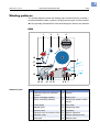
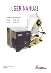
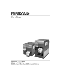
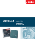
04/07 Rev. 3.05-01
OPERATING INSTRUCTIONS
DPM – PEM
Setup
Winding patterns ........................................... 2
DPM .......................................................... 2
PEM .......................................................... 3
Selecting the printing material ....................... 4
Thermal transfer / direct thermal printing .. 4
Label material ............................................ 4
Thermal transfer ribbon ............................. 5
Inserting label material .................................. 6
DPM .......................................................... 7
PEM .......................................................... 9
Inserting the ribbon ......................................10
Removing spent ribbon ............................10
Inserting a new ribbon roll ........................11
Settings .......................................................12
Ribbon tension .........................................12
Label sensor ............................................13
Adjustment button for printhead pressure 14
(DPM) Dispensing edge ...........................15
(DPM) Dispenser parameters ..................15
Material Parameters ................................16
2
04/07 Rev. 4.01-01
OPERATING INSTRUCTIONS
Setup
DPM – PEM
Winding patterns
The winding diagram shows the winding paths of label material („material“)
and thermotransfer ribbon („ribbon“) through the two types of print modules.
¯ Only specially trained staff to insert and change the ribbons and material.
DPM
1
2
3
4
18
5
17
16
15
6
14 13
[1]
Names of parts
12 11 10
9 8 7
Material and ribbon path in the DPM (left version).
No. Name
No. Name
1
Adjustment knob for printhead
pressure
10
Opener
2
Ribbon rewinding mandrel
11
Brake roller
3
Ribbon unwinding mandrel
12
Adjustment wheel for label
sensor
4
Control panel
13
Print roller
5
Material guide
14
Dispensing edge
6
Pressure roller
15
Printhead
7
Pressure lever for pressure roller 16
Ribbon deflection
8
Deflection roller
17
Ribbon deflection roller
9
Feed roller
18
Ribbon roller
[Tab. 1]
DPM operating parts.
3
04/07 Rev. 4.01-01
OPERATING INSTRUCTIONS
Setup
DPM – PEM
PEM
1
2
3
4
13
12
11
10
9
[2]
Names of parts
8
7 6
5
Material and ribbon path in the PEM (left version)
No. Name
No. Name
1
Adjustment knob for printhead
pressure
8
Adjustment wheel for label
sensor
2
Ribbon rewinding mandrel
9
Print roller
3
Ribbon unwinding mandrel
10
Printhead
4
Control panel
11
Ribbon deflection
5
Material guide
12
Ribbon deflection roll
6
Opener
13
Ribbon roller
7
Feed roller
14
[Tab. 2]
PEM operating parts.
4
04/07 Rev. 4.01-01
OPERATING INSTRUCTIONS
Setup
DPM – PEM
Selecting the printing material
Thermal transfer / direct thermal printing
DPM and PEM print modules can print onto label material using the direct
thermal mode or thermal transfer mode.
Direct thermal
Direct thermal printing is done without ribbon. The direct thermal process
requires label material with a temperature-sensitive coating. The printout is
produced by applying precise bursts of heat to the material under the
printhead. This changes the colour of the coating.
Thermal
transfer
Thermal transfer printing is done with (thermal transfer) ribbon on “normal”
label material. The printout is produced by applying precise bursts of heat to
the thermal transfer ribbon under the printhead. This transfers the colour
particles to the label.
Label material
DPM/PEM modules were developed for printing on self-adhesive stock, PEM
modules can additionally print on tagstock.
Pay attention to the following factors when selecting label material:
•
•
•
The roughness of the material surface.
The printhead temperature required for the colour transfer.
Size of the material roll. The following dimensions need to be checked:
Outside-/inside diameter of the material roll and the material width
Material
roughness
If the material is very rough, the printhead will be worn down more quickly
than when using a smooth material. This is an important aspect of thermal
printing. With thermal transfer printing, this doesn’t pose such a problem,
because you can – and indeed should – select a ribbon that is wider than the
material. This means that the printhead is protected over the entire width of
the material.
Printhead
temperature
High printhead temperatures can similarly cause problems. The material and
the ribbon take longer to cool. As a result, the print quality may degrade –
particularly at high print speeds. The printhead also wears down more
quickly.
¯ The printing result is highly dependent on the right combination of label
material and thermal transfer ribbon. The surface of the label material
determines which thermal transfer ribbons produces the best adhesion.
Unsuitable ribbons can lead to poor printing results.
P Further information can be found in the topic section Technical data, section
“Label material”.
5
04/07 Rev. 4.01-01
OPERATING INSTRUCTIONS
Setup
DPM – PEM
Thermal transfer ribbon
The following is recommended for thermal transfer ribbons:
•
•
•
•
The back of the ribbon should be coated so that it produces no static or
friction (Backcoating). If this isn’t the case, the printhead may be damaged by
static discharge coming off the ribbon surface.
The ribbons need to be designed for “corner edge” printheads.
Ribbons should be able to handle print speeds of up to 400 mm/s (16 ips).
Size of the ribbon roll: The following dimensions need to be checked: outside/
inside diameter of the ribbon roll, ribbon width.
CAUTION! - Thermal transfer ribbons without these properties can degrade
the performance of the printer and the print quality as well as damage the
printhead!
Armor APR 600 (Avery part no. 2240-600-xxx) is a recommended ribbon
type.
¯ The thermal transfer ribbon should only be slightly wider than the label
material.
– If an overly narrow ribbon is used, the border of the label material interferes
with the printhead – which wears it down more quickly.
– If an overly wide ribbon is used, creasing may occur in the ribbon. This can
led to poor printing results.
P For more details on the permissible dimensions of ribbon rolls, refer to
Technical data, “Thermal Transfer Ribbon”.
6
04/07 Rev. 4.01-01
OPERATING INSTRUCTIONS
Setup
DPM – PEM
Inserting label material
WARNING!
• Rotating parts can trap items and draw them in!
« When working on the printer, do not wear loose jewellery, long sleeves,
long hair, and similar.
« Close the printer cover before printing.
• During operation, the printhead can become hot.
« Be careful when touching the printhead!
Label material must be fed to the DPM/
PEM using the equipment in which the
module has been installed. This also
applies to rewinding the backing paper
(DPM).
P For information on the design
requirements, refer to the “Setup” section
of the Service manual.
7
04/07 Rev. 4.01-01
OPERATING INSTRUCTIONS
Setup
DPM – PEM
DPM
1. Open the rear hood.
A
2. Adjusting the material guide to fit the width
of the label material. To do this, release
the thumb screw [1A] on the outer side of
the material guide, slide the material guide
[1B] across at right angles to the feed
direction and retighten the thumb screw.
B
¯ The material should insert easily
through the guides.
[1]
Adjusting the material guide (B) to fit the material width.
3. Press the red opener [2A] to raise the
pressure rollers [2B]. Keeping the opener
depressed, insert the label material under
the pressure rollers and printhead [3B].
4. Keeping the opener depressed, reposition
the pressure rollers [3A] by moving them
laterally.
¯ The pressure rollers must apply an
A
even pressure to the material.
[2]
Pressing the opener to insert the material.
A
A
B
P (continued on the next page)
[3]
Repositioning the pressure rollers (A)
8
04/07 Rev. 4.01-01
OPERATING INSTRUCTIONS
Setup
DPM – PEM
5. Peel off about 50cm of labels from the
backing paper [4].
[4]
Peeling off labels from the backing paper.
6. Open the pressure lever [5A]. To do this,
push the lever downwards.
7. Guide the backing paper under the print
module towards the rear and insert as
shown [5].
A
[5]
8. 5“/6“-modules: Loosen the two thumb
screws [6B] at the spring-suspended
blocks. Position the spring-suspended
blocks [6A] in a way that the contact rolls
press symmetrically on the backing paper.
Retighten the thumb screws.
4“-module: Loosen the thumb screw [6B].
Position the spring-suspended block [6A]
in a way that the contact roll presses in the
middle on the backing paper. Retighten the
thumb screw.
Inserting the backing paper.
B
A
[6]
Repositioning the pressure rollers (A).
[7]
Close the lever.
9. Pull the backing paper taut from the back
and close the pressure lever [7].
9
04/07 Rev. 4.01-01
OPERATING INSTRUCTIONS
Setup
DPM – PEM
PEM
1. Open the hood.
2. Adjust the material guide to fit the width of
the label material. To do this, release the
thumb screw [8A] on the outer side of the
material guide, slide the material guide
[8B] to the material edge and retighten the
thumb screw.
A
¯ The material should insert easily
B
through the guides.
3. Push the label material through the guides
up to the contact pressure rollers.
4. Press the online and feed buttons simultaneously to pull the material in. Hold the
buttons pressed, until the material end is
positioned under the printhead.
C
[8]
Adapt the material guiding (B) to the material width.
[9]
Close the green lever (arrow).
Alternative to steps 3-4:
1. Release the pressure roll. To do so, turn
the green [8C] lever anti-clockwise.
2. Push the material end through the material
guiding, until it is under the printhead.
3. Close the green lever [9].
10
04/07 Rev. 4.01-01
OPERATING INSTRUCTIONS
Setup
DPM – PEM
Inserting the ribbon
WARNING!
• Rotating parts can trap items and draw them in!
« When working on the printer, do not wear loose jewellery, long sleeves,
long hair, and similar.
« Close the printer cover before printing.
• During operation, the printhead can become hot.
« Be careful when touching the printhead!
¯
Skip this section if you intend to print
directly onto thermal material.
¯ The pictures in this section show a
DPM, but are also valid for a PEM.
P For information on choosing a suitable
thermal transfer ribbon, refer to section
Selecting the printing material on page 4.
Removing spent ribbon
CAUTION! - If the diameter of the
ribbon wound on the take-up roll
becomes too great, the machine’s
operation will be impaired.
« Always remove a used ribbon before
inserting a new ribbon roll.
Assuming spent ribbon has gathered on
the rewinding mandrel:
1. Remove the roll of used ribbon from the
rewinding mandrel.
2. Pull the empty ribbon core off the unwinding mandrel and put it on the rewinding
mandrel.
3. Put the ribbon roll on the unwinding
mandrel.
4. Insert the ribbon as described in the following.
11
04/07 Rev. 4.01-01
OPERATING INSTRUCTIONS
Setup
DPM – PEM
Inserting a new ribbon roll
1. Open the hood.
2. Put the ribbon roll on the lower right ribbon
mandrel [10C]. Put an empty take-up
sleeve on the upper left ribbon mandrel.
B
¯ The ribbon must unwind anti-clockwise
(Only valid for ribbon rolls which have the
coloured side facing inwards).
3. Guide the ribbon end under the ribbon
deflection [10B] and thread through to the
side of the printhead [10A].
A
C
[10] Inserting the ribbon roll onto the ribbon unwinding mandrel
(C).
4. Pull the ribbon under the printhead from
the side, then, unwinding some ribbon,
smoothen it out [11].
[11] Smoothening out the ribbon.
5. Draw ribbon upwards and guide it as
shown [12] around the ribbon roller [12A],
the ribbon deflection roller [12B] and the
strain relief [12C] .
A
6. Attach the ribbon end to the empty take-up
sleeve.
Winding direction: clockwise [13A].
B
C
[12] A Ribbon roller
B Ribbon deflection roll
C Strain relief
A
[13] Winding direction of ribbon rewinding mandrel (A)
12
04/07 Rev. 4.01-01
OPERATING INSTRUCTIONS
Setup
DPM – PEM
Settings
Ribbon tension
To achieve an optimal print result, the
ribbon has to run without creases. This is
achieved by correctly setting the torque for
the rewinding mandrel and the braking
torque for the unwinding mandrel.
The factory settings cover a wide range of
different ribbon widths. Nevertheless,
adjustment can be necessary if very
narrow or very wide ribbons are being
used.
The braking torque of the ribbon mandrels
can be set by adjusting the red hexagonal
plastic bolts [14A] on the ribbon mandrels.
Turn clockwise to increase the torque.
Caps[14B] protect the bolts against being
adjusted by accident.
The ribbon must run evenly and free of
creases between the mandrels while being
fed through. The following indications can
help you correct the settings:
•
The ribbon is slack or in folds or winds on
to the rewinding mandrel too loosely.
« Increase torque / braking torque (turn the
bolt clockwise).
•
The ribbon clearly stretches or it tears
during printing. The ribbon is not being
transported adequately.
« Decrease torque / braking torque (turn the
bolt anti-clockwise).
A
B
[14] Ribbon mandrels on a PEM.
A Ribbon rewinding mandrel (without cap)
B Ribbon unwinding mandrel (without cap)
13
04/07 Rev. 4.01-01
OPERATING INSTRUCTIONS
Setup
DPM – PEM
Label sensor
The DPM/PEM modules are equipped with
different sensors for punch recognition:
•
•
DPM: Transmission sensor
PEM: Combination of transmission and
reflex sensor
Setting the label sensor
Turning the red adjustment wheel [15B]
moves the sensor up to 80 mm (4“/5“
modules) or 100 mm (6“ modules) across
the material. A dial [15A] displays the
value.
Reading the value:
Value = punch position – 2 mm
A
… whereby the following applies:
•
Punch position:
Distance of the punch from the (inner) edge
of the material[16A].
•
Value:
Value on dial, set by rotating the red wheel.
B
[15] Setting the label sensor
A Dial
B Adjustment wheel
Example: Punch centre = 11 mm from the
left edge; subtracting 2 mm gives a value of
9 mm.
« To make the setting, turn the wheel [15B]
until the desired value is aligned with the
mark[15A].
¯ Round labels: To ensure in those
cases, that the label start is correctly
identified, a punch offset can be preset.
This may be done by manually setting the
printer (Parameter PRINT PARAMETERS >
X - print offset) or by the appropriate control
command.
A
[16] Measuring the punch position (A).
14
04/07 Rev. 4.01-01
OPERATING INSTRUCTIONS
Setup
DPM – PEM
Adjustment button for
printhead pressure
The material width and / or material
thickness influence the pressure applied by
the thermal transfer printhead on the feed
roller.
There are three possible settings for
pressure [18]:
I
Setting for thin / narrow material
II Setting for material of medium width /
thickness
III Setting for thick / broad material
Setting
The red adjustment screw [17A] [18] is
located above the ribbon roller in the front
plate and can be adjusted with a coin or
large screwdriver.
A
« To set medium pressure, turn the arrow
[18A] to position „II“ until it slots gently into
place.
« To set a higher pressure, turn the arrow to
position „III“ until it slots gently into place.
CAUTION! - Failure to set for the
correct pressure causes the printhead
to wear down more quickly and leads
thus to a shorter service life.
« Always select the lightest possible
pressure necessary to produce an
acceptable print result.
[17] Adjustment knob (A) for the printhead pressure.
A
« Excessive pressure can lead to the
premature wearout of the printhead.
Factory settings:
Setting „I“, for thin / narrow material
[18] Adjustment knob (A) for the printhead pressure.
15
04/07 Rev. 4.01-01
OPERATING INSTRUCTIONS
Setup
DPM – PEM
(DPM) Dispensing edge
¯ Only for DPM.
By inclining the dispensing edge, the
dispensing position can be fine adjusted
without having to change the machine
position:
1. Undo the screws [19B] on both of the side
mounting plates. Access the screws from
beneath.
Tool: 2.5 mm Allen key
2. Turn the dispensing edge [19A] to the
desired position.
3. Tighten the screws.
A
B
[19] Long dispensing edge (option) (feed roller disassembled
for better viewing).
(DPM) Dispenser parameters
¯ Only for DPM.
Set the following parameters prior to first
operating the machine.
•
PRINT PARAMETERS > Dispense Mode
Determines sequence of the printerdispenser process (normal 1:1 mode,
batch mode or true 1:1 mode)
PRINT PARAMETERS > Dispenseposition
Setting the adhesive edge, with which the
label after dispensing adheres to the
backing paper[20].
•
SYSTEM PARAMETER > Start source
Setting the trigger signal source for the
printer-dispenser process (foot switch,
sensor or USI)
P For details on how to set parameters, refer
to Information on printouts and parameters
in the “Using the Parameter Menu” section.
Dispensed label
Dispense position
Dispensing edge
Backing paper
Z0040E.cdr
•
[20] Dispensing position (=home position) shown schematically.
16
04/07 Rev. 4.01-01
OPERATING INSTRUCTIONS
DPM – PEM
Material Parameters
Using the following three parameters, you
can tell the DPM/PEM how you want the
labelling material to be processed:
•
PRINT PARAMETERS > Material type
Sets material type (punched or endless).
•
PRINT PARAMETERS > Material length
Sets material length (measured from label
start to label start, that is label length plus
one gap length). Setting not relevant for
endless material.
•
PRINT PARAMETERS > Material width
Sets material width.
•
SYSTEM PARAMETER > Light sens. type
Applies only to PEM. Sensor type (reflex or
transmission) set according to the material
(reflex marks or punches)
P For details on how to set parameters, refer
to Information on printouts and parameters
in the “Using the Parameter Menu” section.
Setup