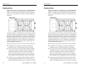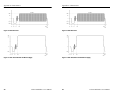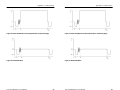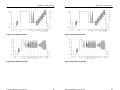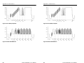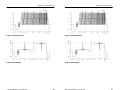
1
User Manual User Manual TSG 95 Pathfindert PAL/NTSC Signal Generator TSG 95 Pathfindert PAL/NTSC Signal Generator 070-8916-06 070-8916-06 www.tektronix.com www.tektronix.com Copyright © Tektronix, Inc. All rights reserved. Copyright © Tektronix, Inc. All rights reserved. Tektronix products are covered by U.S. and foreign patents, issued and pending. Information in this publication supercedes that in all previously published material. Specifications and price change privileges reserved. Tektronix products are covered by U.S. and foreign patents, issued and pending. Information in this publication supercedes that in all previously published material. Specifications and price change privileges reserved. Printed in the U.S.A. Printed in the U.S.A. Tektronix, Inc., P.O. Box 1000, Wilsonville, OR 97070–1000 Tektronix, Inc., P.O. Box 1000, Wilsonville, OR 97070–1000 TEKTRONIX and TEK are registered trademarks of Tektronix, Inc. TEKTRONIX and TEK are registered trademarks of Tektronix, Inc. WARRANTY WARRANTY Tektronix warrants that the products that it manufactures and sells will be free from defects in materials and workmanship for a period of one (1) year from the date of shipment. If a product proves defective during this warranty period, Tektronix, at its option, either will repair the defective product without charge for parts and labor, or will provide a replacement in exchange for the defective product. Tektronix warrants that the products that it manufactures and sells will be free from defects in materials and workmanship for a period of one (1) year from the date of shipment. If a product proves defective during this warranty period, Tektronix, at its option, either will repair the defective product without charge for parts and labor, or will provide a replacement in exchange for the defective product. In order to obtain service under this warranty, Customer must notify Tektronix of the defect before the expiration of the warranty period and make suitable arrangements for the performance of service. Customer shall be responsible for packaging and shipping the defective product to the service center designated by Tektronix, with shipping charges prepaid. Tektronix shall pay for the return of the product to Customer if the shipment is to a location within the country in which the Tektronix service center is located. Customer shall be responsible for paying all shipping charges, duties, taxes, and any other charges for products returned to any other locations. In order to obtain service under this warranty, Customer must notify Tektronix of the defect before the expiration of the warranty period and make suitable arrangements for the performance of service. Customer shall be responsible for packaging and shipping the defective product to the service center designated by Tektronix, with shipping charges prepaid. Tektronix shall pay for the return of the product to Customer if the shipment is to a location within the country in which the Tektronix service center is located. Customer shall be responsible for paying all shipping charges, duties, taxes, and any other charges for products returned to any other locations. This warranty shall not apply to any defect, failure or damage caused by improper use or improper or inadequate maintenance and care. Tektronix shall not be obligated to furnish service under this warranty a) to repair damage resulting from attempts by personnel other than Tektronix representatives to install, repair or service the product; b) to repair damage resulting from improper use or connection to incompatible equipment; c) to repair any damage or malfunction caused by the use of non-Tektronix supplies; or d) to service a product that has been modified or integrated with other products when the effect of such modification or integration increases the time or difficulty of servicing the product. This warranty shall not apply to any defect, failure or damage caused by improper use or improper or inadequate maintenance and care. Tektronix shall not be obligated to furnish service under this warranty a) to repair damage resulting from attempts by personnel other than Tektronix representatives to install, repair or service the product; b) to repair damage resulting from improper use or connection to incompatible equipment; c) to repair any damage or malfunction caused by the use of non-Tektronix supplies; or d) to service a product that has been modified or integrated with other products when the effect of such modification or integration increases the time or difficulty of servicing the product. THIS WARRANTY IS GIVEN BY TEKTRONIX IN LIEU OF ANY OTHER WARRANTIES, EXPRESS OR IMPLIED. TEKTRONIX AND ITS VENDORS DISCLAIM ANY IMPLIED WARRANTIES OF MERCHANTABILITY OR FITNESS FOR A PARTICULAR PURPOSE. TEKTRONIX’ RESPONSIBILITY TO REPAIR OR REPLACE DEFECTIVE PRODUCTS IS THE SOLE AND EXCLUSIVE REMEDY PROVIDED TO THE CUSTOMER FOR BREACH OF THIS WARRANTY. TEKTRONIX AND ITS VENDORS WILL NOT BE LIABLE FOR ANY INDIRECT, SPECIAL, INCIDENTAL, OR CONSEQUENTIAL DAMAGES IRRESPECTIVE OF WHETHER TEKTRONIX OR THE VENDOR HAS ADVANCE NOTICE OF THE POSSIBILITY OF SUCH DAMAGES. THIS WARRANTY IS GIVEN BY TEKTRONIX IN LIEU OF ANY OTHER WARRANTIES, EXPRESS OR IMPLIED. TEKTRONIX AND ITS VENDORS DISCLAIM ANY IMPLIED WARRANTIES OF MERCHANTABILITY OR FITNESS FOR A PARTICULAR PURPOSE. TEKTRONIX’ RESPONSIBILITY TO REPAIR OR REPLACE DEFECTIVE PRODUCTS IS THE SOLE AND EXCLUSIVE REMEDY PROVIDED TO THE CUSTOMER FOR BREACH OF THIS WARRANTY. TEKTRONIX AND ITS VENDORS WILL NOT BE LIABLE FOR ANY INDIRECT, SPECIAL, INCIDENTAL, OR CONSEQUENTIAL DAMAGES IRRESPECTIVE OF WHETHER TEKTRONIX OR THE VENDOR HAS ADVANCE NOTICE OF THE POSSIBILITY OF SUCH DAMAGES. Table of Contents Table of Contents Warranty . . . . . . . . . . . . . . . . . . . . . . . . . . . . . . . . . . . . . . . . . . . iii Warranty . . . . . . . . . . . . . . . . . . . . . . . . . . . . . . . . . . . . . . . . . . . iii List of Figures . . . . . . . . . . . . . . . . . . . . . . . . . . . . . . . . . . . . . . . viii List of Figures . . . . . . . . . . . . . . . . . . . . . . . . . . . . . . . . . . . . . . . viii List of Tables . . . . . . . . . . . . . . . . . . . . . . . . . . . . . . . . . . . . . . . . x List of Tables . . . . . . . . . . . . . . . . . . . . . . . . . . . . . . . . . . . . . . . . x General Safety Summary . . . . . . . . . . . . . . . . . . . . . . . . . . . . . . xi General Safety Summary . . . . . . . . . . . . . . . . . . . . . . . . . . . . . . xi Getting Started . . . . . . . . . . . . . . . . . . . . . . . . . . . . . . . . . . . . . . Supplying Power . . . . . . . . . . . . . . . . . . . . . . . . . . . . . . . . . . . Connecting the TSG 95 . . . . . . . . . . . . . . . . . . . . . . . . . . . . . . Keypad and Display Conventions . . . . . . . . . . . . . . . . . . . . . . Definitions . . . . . . . . . . . . . . . . . . . . . . . . . . . . . . . . . . . . . . . . Preliminary Settings . . . . . . . . . . . . . . . . . . . . . . . . . . . . . . . . Choose the Video Standard/Signal Set . . . . . . . . . . . . . . . Set the Battery Type . . . . . . . . . . . . . . . . . . . . . . . . . . . . . Enable (Disable) Auto Power Down . . . . . . . . . . . . . . . . . Other Settings . . . . . . . . . . . . . . . . . . . . . . . . . . . . . . . . . . . . . 1 2 3 4 5 5 5 6 6 6 Getting Started . . . . . . . . . . . . . . . . . . . . . . . . . . . . . . . . . . . . . . Supplying Power . . . . . . . . . . . . . . . . . . . . . . . . . . . . . . . . . . . Connecting the TSG 95 . . . . . . . . . . . . . . . . . . . . . . . . . . . . . . Keypad and Display Conventions . . . . . . . . . . . . . . . . . . . . . . Definitions . . . . . . . . . . . . . . . . . . . . . . . . . . . . . . . . . . . . . . . . Preliminary Settings . . . . . . . . . . . . . . . . . . . . . . . . . . . . . . . . Choose the Video Standard/Signal Set . . . . . . . . . . . . . . . Set the Battery Type . . . . . . . . . . . . . . . . . . . . . . . . . . . . . Enable (Disable) Auto Power Down . . . . . . . . . . . . . . . . . Other Settings . . . . . . . . . . . . . . . . . . . . . . . . . . . . . . . . . . . . . 1 2 3 4 5 5 5 6 6 6 Operating Basics . . . . . . . . . . . . . . . . . . . . . . . . . . . . . . . . . . . . . Using Your TSG 95 . . . . . . . . . . . . . . . . . . . . . . . . . . . . . . . . . Outputting Test Signals . . . . . . . . . . . . . . . . . . . . . . . . . . . Outputting Audio Tones . . . . . . . . . . . . . . . . . . . . . . . . . . Selecting the Audio Frequency . . . . . . . . . . . . . . . . . . . . . Setting the Audio Tone Level (Amplitude) . . . . . . . . . . . . Inserting Channel–ID Clicks in the Audio . . . . . . . . . . . . Inserting ID Messages . . . . . . . . . . . . . . . . . . . . . . . . . . . . Editing ID Messages . . . . . . . . . . . . . . . . . . . . . . . . . . . . . Positioning ID Messages . . . . . . . . . . . . . . . . . . . . . . . . . . Saving ID Messages . . . . . . . . . . . . . . . . . . . . . . . . . . . . . Recalling ID Messages . . . . . . . . . . . . . . . . . . . . . . . . . . . Setting up an ID Cycle . . . . . . . . . . . . . . . . . . . . . . . . . . . Saving (Storing) Presets . . . . . . . . . . . . . . . . . . . . . . . . . . Recalling Presets . . . . . . . . . . . . . . . . . . . . . . . . . . . . . . . . 7 7 9 10 10 11 11 11 12 12 13 14 14 15 16 Operating Basics . . . . . . . . . . . . . . . . . . . . . . . . . . . . . . . . . . . . . Using Your TSG 95 . . . . . . . . . . . . . . . . . . . . . . . . . . . . . . . . . Outputting Test Signals . . . . . . . . . . . . . . . . . . . . . . . . . . . Outputting Audio Tones . . . . . . . . . . . . . . . . . . . . . . . . . . Selecting the Audio Frequency . . . . . . . . . . . . . . . . . . . . . Setting the Audio Tone Level (Amplitude) . . . . . . . . . . . . Inserting Channel–ID Clicks in the Audio . . . . . . . . . . . . Inserting ID Messages . . . . . . . . . . . . . . . . . . . . . . . . . . . . Editing ID Messages . . . . . . . . . . . . . . . . . . . . . . . . . . . . . Positioning ID Messages . . . . . . . . . . . . . . . . . . . . . . . . . . Saving ID Messages . . . . . . . . . . . . . . . . . . . . . . . . . . . . . Recalling ID Messages . . . . . . . . . . . . . . . . . . . . . . . . . . . Setting up an ID Cycle . . . . . . . . . . . . . . . . . . . . . . . . . . . Saving (Storing) Presets . . . . . . . . . . . . . . . . . . . . . . . . . . Recalling Presets . . . . . . . . . . . . . . . . . . . . . . . . . . . . . . . . 7 7 9 10 10 11 11 11 12 12 13 14 14 15 16 Reference . . . . . . . . . . . . . . . . . . . . . . . . . . . . . . . . . . . . . . . . . . . The Utility Menu . . . . . . . . . . . . . . . . . . . . . . . . . . . . . . . . . . . Creating/Editing the User Signal Set . . . . . . . . . . . . . . . . . . . The Calibration Submenu . . . . . . . . . . . . . . . . . . . . . . . . . . . . 17 17 20 23 Reference . . . . . . . . . . . . . . . . . . . . . . . . . . . . . . . . . . . . . . . . . . . The Utility Menu . . . . . . . . . . . . . . . . . . . . . . . . . . . . . . . . . . . Creating/Editing the User Signal Set . . . . . . . . . . . . . . . . . . . The Calibration Submenu . . . . . . . . . . . . . . . . . . . . . . . . . . . . 17 17 20 23 TSG 95 Pathfinder User Manual i TSG 95 Pathfinder User Manual i Contents Contents Appendix A: Characteristics . . . . . . . . . . . . . . . . . . . . . . . . . . . Safety Standard Compliance . . . . . . . . . . . . . . . . . . . . . . . . . . EMI Compliance . . . . . . . . . . . . . . . . . . . . . . . . . . . . . . . . . . . Specification Tables . . . . . . . . . . . . . . . . . . . . . . . . . . . . . . . . PAL Waveform Diagrams . . . . . . . . . . . . . . . . . . . . . . . . . . . . NTSC Waveform Diagrams . . . . . . . . . . . . . . . . . . . . . . . . . . NTSC JAPAN (No Setup) Waveform Diagrams . . . . . . . . . . 27 27 27 28 43 56 67 Appendix A: Characteristics . . . . . . . . . . . . . . . . . . . . . . . . . . . Safety Standard Compliance . . . . . . . . . . . . . . . . . . . . . . . . . . EMI Compliance . . . . . . . . . . . . . . . . . . . . . . . . . . . . . . . . . . . Specification Tables . . . . . . . . . . . . . . . . . . . . . . . . . . . . . . . . PAL Waveform Diagrams . . . . . . . . . . . . . . . . . . . . . . . . . . . . NTSC Waveform Diagrams . . . . . . . . . . . . . . . . . . . . . . . . . . NTSC JAPAN (No Setup) Waveform Diagrams . . . . . . . . . . 27 27 27 28 43 56 67 Appendix B: Replaceable Parts . . . . . . . . . . . . . . . . . . . . . . . . . 69 Appendix B: Replaceable Parts . . . . . . . . . . . . . . . . . . . . . . . . . 69 Appendix C: User Service . . . . . . . . . . . . . . . . . . . . . . . . . . . . . Battery Hints . . . . . . . . . . . . . . . . . . . . . . . . . . . . . . . . . . . . . . The BATTERY LOW Message . . . . . . . . . . . . . . . . . . . . . Low Battery Shutdown . . . . . . . . . . . . . . . . . . . . . . . . . . . Preventive Maintenance . . . . . . . . . . . . . . . . . . . . . . . . . . . . . 71 71 71 71 72 Appendix C: User Service . . . . . . . . . . . . . . . . . . . . . . . . . . . . . Battery Hints . . . . . . . . . . . . . . . . . . . . . . . . . . . . . . . . . . . . . . The BATTERY LOW Message . . . . . . . . . . . . . . . . . . . . . Low Battery Shutdown . . . . . . . . . . . . . . . . . . . . . . . . . . . Preventive Maintenance . . . . . . . . . . . . . . . . . . . . . . . . . . . . . 71 71 71 71 72 List of Figures List of Figures Figure 1: PAL 75% Color Bars . . . . . . . . . . . . . . . . . . . . . . . . Figure 2: PAL 100% Color Bars . . . . . . . . . . . . . . . . . . . . . . . Figure 3: PAL 75% Red and Red Field . . . . . . . . . . . . . . . . . . Figure 4: PAL 100% Red . . . . . . . . . . . . . . . . . . . . . . . . . . . . Figure 5: PAL Convergence (vertical lines) . . . . . . . . . . . . . . Figure 6: PAL Convergence (horizontal lines) . . . . . . . . . . . . Figure 7: PAL Pluge . . . . . . . . . . . . . . . . . . . . . . . . . . . . . . . . Figure 8: PAL Green Field . . . . . . . . . . . . . . . . . . . . . . . . . . . Figure 9: PAL Safe Area . . . . . . . . . . . . . . . . . . . . . . . . . . . . . Figure 10: PAL Blue Field . . . . . . . . . . . . . . . . . . . . . . . . . . . Figure 11: PAL 100% Flat Field and Bounce (High) . . . . . . . Figure 12: PAL 50% Flat Field . . . . . . . . . . . . . . . . . . . . . . . . Figure 13: PAL 0% Flat Field and Bounce (Low) . . . . . . . . . Figure 14: PAL Multiburst . . . . . . . . . . . . . . . . . . . . . . . . . . . Figure 15: PAL Reduced Sweep . . . . . . . . . . . . . . . . . . . . . . . Figure 16: PAL 5-Step (Gray Scale) . . . . . . . . . . . . . . . . . . . . Figure 17: PAL Modulated 5-Step . . . . . . . . . . . . . . . . . . . . . ii 43 43 44 44 45 45 46 46 47 48 48 49 49 49 50 50 51 TSG 95 Pathfinder User Manual Figure 1: PAL 75% Color Bars . . . . . . . . . . . . . . . . . . . . . . . . Figure 2: PAL 100% Color Bars . . . . . . . . . . . . . . . . . . . . . . . Figure 3: PAL 75% Red and Red Field . . . . . . . . . . . . . . . . . . Figure 4: PAL 100% Red . . . . . . . . . . . . . . . . . . . . . . . . . . . . Figure 5: PAL Convergence (vertical lines) . . . . . . . . . . . . . . Figure 6: PAL Convergence (horizontal lines) . . . . . . . . . . . . Figure 7: PAL Pluge . . . . . . . . . . . . . . . . . . . . . . . . . . . . . . . . Figure 8: PAL Green Field . . . . . . . . . . . . . . . . . . . . . . . . . . . Figure 9: PAL Safe Area . . . . . . . . . . . . . . . . . . . . . . . . . . . . . Figure 10: PAL Blue Field . . . . . . . . . . . . . . . . . . . . . . . . . . . Figure 11: PAL 100% Flat Field and Bounce (High) . . . . . . . Figure 12: PAL 50% Flat Field . . . . . . . . . . . . . . . . . . . . . . . . Figure 13: PAL 0% Flat Field and Bounce (Low) . . . . . . . . . Figure 14: PAL Multiburst . . . . . . . . . . . . . . . . . . . . . . . . . . . Figure 15: PAL Reduced Sweep . . . . . . . . . . . . . . . . . . . . . . . Figure 16: PAL 5-Step (Gray Scale) . . . . . . . . . . . . . . . . . . . . Figure 17: PAL Modulated 5-Step . . . . . . . . . . . . . . . . . . . . . ii 43 43 44 44 45 45 46 46 47 48 48 49 49 49 50 50 51 TSG 95 Pathfinder User Manual Contents Figure 18: PAL Matrix Signal — CCIR 17 . . . . . . . . . . . . . . Figure 19: PAL Matrix Signal — CCIR Line 330 . . . . . . . . . Figure 20: PAL Matrix Signal — CCIR Line 331 . . . . . . . . . Figure 21: PAL Matrix Signal — CCIR 18 . . . . . . . . . . . . . . Figure 22: PAL Matrix Signal — Sin(x)/x . . . . . . . . . . . . . . . Figure 23: PAL Matrix Signal — 15 kHz Square Wave . . . . . Figure 24: PAL Matrix Signal — Shallow Ramp . . . . . . . . . . Figure 25: PAL Matrix Signal — UK ITS 1 . . . . . . . . . . . . . . Figure 26: PAL Matrix Signal — UK ITS 2 . . . . . . . . . . . . . . Figure 27: NTSC 75% Color Bars . . . . . . . . . . . . . . . . . . . . . Figure 28: NTSC Convergence Components . . . . . . . . . . . . . Figure 29: SMPTE (NTSC) Color Bar Components . . . . . . . Figure 30: NTSC Safe Area Signal Components . . . . . . . . . . Figure 31: NTSC Red Field . . . . . . . . . . . . . . . . . . . . . . . . . . Figure 32: NTSC 30 IRE and 50 IRE Flat Fields . . . . . . . . . . Figure 33: NTSC 100 IRE Flat Field, Field Square Wave, and Bounce (High) . . . . . . . . . . . . . . . . . . . . . . . . . . . . . . . . . . Figure 34: NTSC Black Burst . . . . . . . . . . . . . . . . . . . . . . . . . Figure 35: NTSC 5-Step Staircase (Gray Scale) . . . . . . . . . . . Figure 36: NTSC Multiburst . . . . . . . . . . . . . . . . . . . . . . . . . . Figure 37: NTC7 (NTSC) Composite . . . . . . . . . . . . . . . . . . . Figure 38: NTC7 (NTSC) Combination . . . . . . . . . . . . . . . . . Figure 39: FCC (NTSC) Composite . . . . . . . . . . . . . . . . . . . . Figure 40: NTSC Cable Multiburst . . . . . . . . . . . . . . . . . . . . . Figure 41: NTSC Cable Sweep . . . . . . . . . . . . . . . . . . . . . . . . Figure 42: NTSC SIN(X)/X . . . . . . . . . . . . . . . . . . . . . . . . . . Figure 43: NTSC Matrix . . . . . . . . . . . . . . . . . . . . . . . . . . . . . Figure 44: NTSC 0 IRE No Burst . . . . . . . . . . . . . . . . . . . . . . Figure 45: NTSC Bounce (Low) . . . . . . . . . . . . . . . . . . . . . . . Figure 46: SMPTE (NTSC) Color Bars, No Setup . . . . . . . . . Figure 47: NTSC 75% Color Bars, No Setup . . . . . . . . . . . . . Figure 48: NTSC Red Field, No Setup . . . . . . . . . . . . . . . . . . Figure 49: NTSC Black Burst, No Setup . . . . . . . . . . . . . . . . TSG 95 Pathfinder User Manual 51 52 52 53 53 54 54 55 55 56 56 57 58 60 60 61 61 62 62 63 63 64 64 65 65 66 66 66 67 68 68 68 iii Contents Figure 18: PAL Matrix Signal — CCIR 17 . . . . . . . . . . . . . . Figure 19: PAL Matrix Signal — CCIR Line 330 . . . . . . . . . Figure 20: PAL Matrix Signal — CCIR Line 331 . . . . . . . . . Figure 21: PAL Matrix Signal — CCIR 18 . . . . . . . . . . . . . . Figure 22: PAL Matrix Signal — Sin(x)/x . . . . . . . . . . . . . . . Figure 23: PAL Matrix Signal — 15 kHz Square Wave . . . . . Figure 24: PAL Matrix Signal — Shallow Ramp . . . . . . . . . . Figure 25: PAL Matrix Signal — UK ITS 1 . . . . . . . . . . . . . . Figure 26: PAL Matrix Signal — UK ITS 2 . . . . . . . . . . . . . . Figure 27: NTSC 75% Color Bars . . . . . . . . . . . . . . . . . . . . . Figure 28: NTSC Convergence Components . . . . . . . . . . . . . Figure 29: SMPTE (NTSC) Color Bar Components . . . . . . . Figure 30: NTSC Safe Area Signal Components . . . . . . . . . . Figure 31: NTSC Red Field . . . . . . . . . . . . . . . . . . . . . . . . . . Figure 32: NTSC 30 IRE and 50 IRE Flat Fields . . . . . . . . . . Figure 33: NTSC 100 IRE Flat Field, Field Square Wave, and Bounce (High) . . . . . . . . . . . . . . . . . . . . . . . . . . . . . . . . . . Figure 34: NTSC Black Burst . . . . . . . . . . . . . . . . . . . . . . . . . Figure 35: NTSC 5-Step Staircase (Gray Scale) . . . . . . . . . . . Figure 36: NTSC Multiburst . . . . . . . . . . . . . . . . . . . . . . . . . . Figure 37: NTC7 (NTSC) Composite . . . . . . . . . . . . . . . . . . . Figure 38: NTC7 (NTSC) Combination . . . . . . . . . . . . . . . . . Figure 39: FCC (NTSC) Composite . . . . . . . . . . . . . . . . . . . . Figure 40: NTSC Cable Multiburst . . . . . . . . . . . . . . . . . . . . . Figure 41: NTSC Cable Sweep . . . . . . . . . . . . . . . . . . . . . . . . Figure 42: NTSC SIN(X)/X . . . . . . . . . . . . . . . . . . . . . . . . . . Figure 43: NTSC Matrix . . . . . . . . . . . . . . . . . . . . . . . . . . . . . Figure 44: NTSC 0 IRE No Burst . . . . . . . . . . . . . . . . . . . . . . Figure 45: NTSC Bounce (Low) . . . . . . . . . . . . . . . . . . . . . . . Figure 46: SMPTE (NTSC) Color Bars, No Setup . . . . . . . . . Figure 47: NTSC 75% Color Bars, No Setup . . . . . . . . . . . . . Figure 48: NTSC Red Field, No Setup . . . . . . . . . . . . . . . . . . Figure 49: NTSC Black Burst, No Setup . . . . . . . . . . . . . . . . TSG 95 Pathfinder User Manual 51 52 52 53 53 54 54 55 55 56 56 57 58 60 60 61 61 62 62 63 63 64 64 65 65 66 66 66 67 68 68 68 iii Contents Contents List of Tables List of Tables Table 1: TSG 95 Video Test Signals . . . . . . . . . . . . . . . . . . . . Table 2: General PAL Test Signal Characteristics . . . . . . . . . Table 3: Individual PAL Test Signal Characteristics . . . . . . . Table 4: PAL Vertical Interval Test Signals (VITS) . . . . . . . . Table 5: General NTSC Test Signal Characteristics . . . . . . . Table 6: Individual NTSC Test Signal Characteristics . . . . . Table 7: NTSC JAPAN Test Signal Characteristics . . . . . . . . Table 8: NTSC and NTSC JAPAN VITS . . . . . . . . . . . . . . . . Table 9: Character Identification . . . . . . . . . . . . . . . . . . . . . . Table 10: Audio Tone . . . . . . . . . . . . . . . . . . . . . . . . . . . . . . . Table 11: Power Supply . . . . . . . . . . . . . . . . . . . . . . . . . . . . . Table 12: Physical Characteristics . . . . . . . . . . . . . . . . . . . . . Table 13: Environmental Characteristics . . . . . . . . . . . . . . . . iv 9 28 30 32 33 35 39 40 40 40 41 41 42 TSG 95 Pathfinder User Manual Table 1: TSG 95 Video Test Signals . . . . . . . . . . . . . . . . . . . . Table 2: General PAL Test Signal Characteristics . . . . . . . . . Table 3: Individual PAL Test Signal Characteristics . . . . . . . Table 4: PAL Vertical Interval Test Signals (VITS) . . . . . . . . Table 5: General NTSC Test Signal Characteristics . . . . . . . Table 6: Individual NTSC Test Signal Characteristics . . . . . Table 7: NTSC JAPAN Test Signal Characteristics . . . . . . . . Table 8: NTSC and NTSC JAPAN VITS . . . . . . . . . . . . . . . . Table 9: Character Identification . . . . . . . . . . . . . . . . . . . . . . Table 10: Audio Tone . . . . . . . . . . . . . . . . . . . . . . . . . . . . . . . Table 11: Power Supply . . . . . . . . . . . . . . . . . . . . . . . . . . . . . Table 12: Physical Characteristics . . . . . . . . . . . . . . . . . . . . . Table 13: Environmental Characteristics . . . . . . . . . . . . . . . . iv 9 28 30 32 33 35 39 40 40 40 41 41 42 TSG 95 Pathfinder User Manual General Safety Summary General Safety Summary Review the following safety precautions to avoid injury and prevent damage to this product or any products connected to it. To avoid potential hazards, use this product only as specified. Review the following safety precautions to avoid injury and prevent damage to this product or any products connected to it. To avoid potential hazards, use this product only as specified. Only qualified personnel should perform service procedures. Only qualified personnel should perform service procedures. To Avoid Fire or Personal Injury To Avoid Fire or Personal Injury Observe All Terminal Ratings. To avoid fire or shock hazard, observe all ratings and markings on the product. Consult the product manual for further ratings information before making connections to the product. Observe All Terminal Ratings. To avoid fire or shock hazard, observe all ratings and markings on the product. Consult the product manual for further ratings information before making connections to the product. The common terminal is at ground potential. Do not connect the common terminal to elevated voltages. The common terminal is at ground potential. Do not connect the common terminal to elevated voltages. Replace Batteries Properly. Replace batteries only with the proper type and rating specified. Replace Batteries Properly. Replace batteries only with the proper type and rating specified. Recharge Batteries Properly. Recharge batteries for the recommended charge cycle only. Recharge Batteries Properly. Recharge batteries for the recommended charge cycle only. Use Proper AC Adapter. Use only the AC adapter specified for this product. Use Proper AC Adapter. Use only the AC adapter specified for this product. Do Not Operate Without Covers. Do not operate this product with covers or panels removed. Do Not Operate Without Covers. Do not operate this product with covers or panels removed. Use Proper Fuse. Use only the fuse type and rating specified for this product. Use Proper Fuse. Use only the fuse type and rating specified for this product. Avoid Exposed Circuitry. Do not touch exposed connections and components when power is present. Avoid Exposed Circuitry. Do not touch exposed connections and components when power is present. Do Not Operate With Suspected Failures. If you suspect there is damage to this product, have it inspected by qualified service personnel. Do Not Operate With Suspected Failures. If you suspect there is damage to this product, have it inspected by qualified service personnel. Do Not Operate in Wet/Damp Conditions. Do Not Operate in Wet/Damp Conditions. Do Not Operate in an Explosive Atmosphere. Do Not Operate in an Explosive Atmosphere. TSG 95 Pathfinder User Manual v TSG 95 Pathfinder User Manual v Contents Contents Safety Terms and Symbols Safety Terms and Symbols Terms in This Manual. These terms may appear in this manual: Terms in This Manual. These terms may appear in this manual: WARNING. Warning statements identify conditions or practices that could result in injury or loss of life. WARNING. Warning statements identify conditions or practices that could result in injury or loss of life. CAUTION. Caution statements identify conditions or practices that could result in damage to this product or other property. CAUTION. Caution statements identify conditions or practices that could result in damage to this product or other property. Terms on the Product. These terms may appear on the product: Terms on the Product. These terms may appear on the product: DANGER indicates an injury hazard immediately accessible as you read the marking. DANGER indicates an injury hazard immediately accessible as you read the marking. WARNING indicates an injury hazard not immediately accessible as you read the marking. WARNING indicates an injury hazard not immediately accessible as you read the marking. CAUTION indicates a hazard to property including the product. CAUTION indicates a hazard to property including the product. Symbols on the Product. These symbols may appear on the product: Symbols on the Product. These symbols may appear on the product: CAUTION Refer to Manual vi Double Insulated CAUTION Refer to Manual Double Insulated Battery Recycling Battery Recycling This product contains a Nickel Cadmium (NiCd) battery, which must be recycled or disposed of properly. For the location of a local battery recycler in the U.S. or Canada, please contact: This product contains a Nickel Cadmium (NiCd) battery, which must be recycled or disposed of properly. For the location of a local battery recycler in the U.S. or Canada, please contact: RBRC Rechargeable Battery Recycling Corp. P.O. Box 141870 Gainesville, Florida 32614 RBRC Rechargeable Battery Recycling Corp. P.O. Box 141870 Gainesville, Florida 32614 (800) BATTERY (800) 227-7379 www.rbrc.com TSG 95 Pathfinder User Manual vi (800) BATTERY (800) 227-7379 www.rbrc.com TSG 95 Pathfinder User Manual Getting Started Getting Started Please read the following statements before using your new TSG 95 Pathfinder, then see the rest of the section for tips on supplying power, making preliminary settings, and connecting the instrument. Please read the following statements before using your new TSG 95 Pathfinder, then see the rest of the section for tips on supplying power, making preliminary settings, and connecting the instrument. WARNING. Install or replace batteries only with the instrument switched OFF and the AC adapter disconnected. Electrical shock or equipment damage can result. WARNING. Install or replace batteries only with the instrument switched OFF and the AC adapter disconnected. Electrical shock or equipment damage can result. CAUTION. Do not attempt to operate the TSG 95 with an improper AC adapter. Damage to the instrument can result. CAUTION. Do not attempt to operate the TSG 95 with an improper AC adapter. Damage to the instrument can result. For best results, use the AC adapter supplied with the instrument. If the supplied adapter is incorrect for the local AC power supply, contact your nearest Tektronix representative. For best results, use the AC adapter supplied with the instrument. If the supplied adapter is incorrect for the local AC power supply, contact your nearest Tektronix representative. The adapter voltage must be 9 to 15 VDC with an open-circuit voltage less than 18 VDC; the adapter connector must have the negative (–) polarity contact in the center. The adapter voltage must be 9 to 15 VDC with an open-circuit voltage less than 18 VDC; the adapter connector must have the negative (–) polarity contact in the center. NOTE. Internal batteries are recommended when using an external power adapter. A loose adapter connector can cause the loss of some user settings and unexpected results the next time the instrument is powered on. NOTE. Internal batteries are recommended when using an external power adapter. A loose adapter connector can cause the loss of some user settings and unexpected results the next time the instrument is powered on. The battery type, disposable or rechargeable, must be selected using through the Utility menu (see page 6). Failure to select the proper battery type can result in damage to the batteries and product. The battery type, disposable or rechargeable, must be selected using through the Utility menu (see page 6). Failure to select the proper battery type can result in damage to the batteries and product. Replace the batteries only with standard AA batteries (1.2–1.5 V, nominal), or the Tektronix rechargeable battery pack listed on page 69. Replace the batteries only with standard AA batteries (1.2–1.5 V, nominal), or the Tektronix rechargeable battery pack listed on page 69. For more information, please contact your nearest Tektronix representative or field office. In the United States and Canada, you can also call the Tektronix information number, 1-800-TEK-WIDE (1-800-835-9433), between 8:00 am and 5:00 pm Pacific time. For more information, please contact your nearest Tektronix representative or field office. In the United States and Canada, you can also call the Tektronix information number, 1-800-TEK-WIDE (1-800-835-9433), between 8:00 am and 5:00 pm Pacific time. TSG 95 Pathfinder User Manual 1 TSG 95 Pathfinder User Manual 1 Getting Started Getting Started Supplying Power Supplying Power 2 The TSG 95 is DC powered. You may power it with the standard AC adapter, the optional 9.6 V NiCad battery pack, eight standard AA batteries, or a “BP” type battery pack with the correct voltage and polarity. The external DC power connector is on the left side of the instrument. The TSG 95 is DC powered. You may power it with the standard AC adapter, the optional 9.6 V NiCad battery pack, eight standard AA batteries, or a “BP” type battery pack with the correct voltage and polarity. The external DC power connector is on the left side of the instrument. To install AA batteries or the battery pack, open the battery compartment of the TSG 95 by pressing down on the cover and sliding it in the direction of the inscribed arrow, as shown above. When the cover tabs line up with the slots in the case, lift the cover away from the instrument. Install batteries in alternating directions as indicated by the graphic molded into the “floor” of the battery compartment. If using the optional battery pack, take the time to identify both contacts and install the pack properly. To install AA batteries or the battery pack, open the battery compartment of the TSG 95 by pressing down on the cover and sliding it in the direction of the inscribed arrow, as shown above. When the cover tabs line up with the slots in the case, lift the cover away from the instrument. Install batteries in alternating directions as indicated by the graphic molded into the “floor” of the battery compartment. If using the optional battery pack, take the time to identify both contacts and install the pack properly. When selecting a power source for your TSG 95, please remember: When selecting a power source for your TSG 95, please remember: H Attempting to use an improper AC adapter can damage the instrument. See the Caution statement on the previous page. H Attempting to use an improper AC adapter can damage the instrument. See the Caution statement on the previous page. H There is no need to remove the optional NiCad battery pack for recharging. The TSG 95 will “trickle charge” the battery pack whenever the standard AC adapter is used. Recharging the battery pack fully can take up to 16 hours. Note that charging will occur only if the adapter supplies at least 12 V; make sure that the adapter you use is appropriate for the local AC supply. H There is no need to remove the optional NiCad battery pack for recharging. The TSG 95 will “trickle charge” the battery pack whenever the standard AC adapter is used. Recharging the battery pack fully can take up to 16 hours. Note that charging will occur only if the adapter supplies at least 12 V; make sure that the adapter you use is appropriate for the local AC supply. H AA batteries are not included with the instrument; obtain them locally. Rechargeable AA batteries may be used, but they will NOT be recharged automatically by the AC adapter. To recharge H AA batteries are not included with the instrument; obtain them locally. Rechargeable AA batteries may be used, but they will NOT be recharged automatically by the AC adapter. To recharge TSG 95 Pathfinder User Manual 2 TSG 95 Pathfinder User Manual Getting Started AA batteries, remove them from the instrument and use an appropriate battery charger. For safety, read and follow the battery charger instructions. Do NOT attempt to recharge standard alkaline batteries. Getting Started AA batteries, remove them from the instrument and use an appropriate battery charger. For safety, read and follow the battery charger instructions. Do NOT attempt to recharge standard alkaline batteries. H After a minute with no key-press, the TSG 95 will automatically switch to lock out mode (as if you had pressed the Lock Out key); the display back light will shut off to conserve battery charge. When you want to resume keypad input, press Lock Out to exit lock out mode. H After a minute with no key-press, the TSG 95 will automatically switch to lock out mode (as if you had pressed the Lock Out key); the display back light will shut off to conserve battery charge. When you want to resume keypad input, press Lock Out to exit lock out mode. H To guard against battery discharge if you forget to turn the TSG 95 off after use, enable Auto Power Down through the Utility menu (see page 6). H To guard against battery discharge if you forget to turn the TSG 95 off after use, enable Auto Power Down through the Utility menu (see page 6). H The TSG 95 can sense low battery voltage. It will warn you when the charge is sufficient for approximately ten more minutes of operation. The instrument will shut itself down when the battery voltage becomes too low for reliable operation. For proper function of these features, the Battery Type must be set correctly in the Utility menu.. Please see “Setting the Battery Type,” which follows. H The TSG 95 can sense low battery voltage. It will warn you when the charge is sufficient for approximately ten more minutes of operation. The instrument will shut itself down when the battery voltage becomes too low for reliable operation. For proper function of these features, the Battery Type must be set correctly in the Utility menu.. Please see “Setting the Battery Type,” which follows. The ON key toggles instrument power On and Off. The ON key toggles instrument power On and Off. Connecting the TSG 95 Connecting the TSG 95 Connect the Pathfinder to your equipment as you would any television test signal generator. Use 75 W coaxial cable (for video) and be sure that the signal path is properly terminated. 1 Connect the Pathfinder to your equipment as you would any television test signal generator. Use 75 W coaxial cable (for video) and be sure that the signal path is properly terminated. 2 1 3 Pin 1 = GND Pin 2 = POS (+) Pin 3 = NEG (–) TSG 95 Pathfinder User Manual 2 3 Pin 1 = GND Pin 2 = POS (+) Pin 3 = NEG (–) 3 TSG 95 Pathfinder User Manual 3 Getting Started Getting Started You may wish to confirm proper operation of your TSG 95—and gain familiarity with it—by first connecting it directly to a video or waveform monitor. You may wish to confirm proper operation of your TSG 95—and gain familiarity with it—by first connecting it directly to a video or waveform monitor. A performance verification procedure, which some users may require for acceptance testing, is included in the optional TSG 95 service manual (Tek p/n 070-8917-0x). To order a service manual, please contact your nearest Tektronix representative or field office. A performance verification procedure, which some users may require for acceptance testing, is included in the optional TSG 95 service manual (Tek p/n 070-8917-0x). To order a service manual, please contact your nearest Tektronix representative or field office. Keypad and Display Conventions Keypad and Display Conventions Please see the Instruction card (p/n 070-8915-00) supplied with your TSG 95 for a “tour” of the keypad and an explanation of the display symbols. For your convenience, the following panels are taken from the card. 4 TSG 95 Pathfinder User Manual Please see the Instruction card (p/n 070-8915-00) supplied with your TSG 95 for a “tour” of the keypad and an explanation of the display symbols. For your convenience, the following panels are taken from the card. 4 TSG 95 Pathfinder User Manual Getting Started Getting Started Definitions Definitions There are two phrases used in this manual that deserve a little explanation. We at Tektronix sincerely hope that these explanations do not confuse you further. There are two phrases used in this manual that deserve a little explanation. We at Tektronix sincerely hope that these explanations do not confuse you further. Signal Set — The group of signals that can be selected through the TSG 95 keypad at a given time. In the preprogrammed signal sets, all of the signals are the same video standard. You may create a “User” signal set, however, that contains both PAL and NTSC signals assigned to the letter keys of your choice, for easy selection. Signal Set — The group of signals that can be selected through the TSG 95 keypad at a given time. In the preprogrammed signal sets, all of the signals are the same video standard. You may create a “User” signal set, however, that contains both PAL and NTSC signals assigned to the letter keys of your choice, for easy selection. Tone Level — One of four predefined audio output amplitudes that may be selected through the Tone menu. The levels (1 through 4) are “named” –10, 0, +4, and +8 dBu and calibrated to those amplitudes when the TSG 95 is manufactured. Qualified personnel, with the appropriate equipment, can rename and readjust the levels between –10 and +10 dBu. See page 24 for more discussion; see the Service manual for instructions. Tone Level — One of four predefined audio output amplitudes that may be selected through the Tone menu. The levels (1 through 4) are “named” –10, 0, +4, and +8 dBu and calibrated to those amplitudes when the TSG 95 is manufactured. Qualified personnel, with the appropriate equipment, can rename and readjust the levels between –10 and +10 dBu. See page 24 for more discussion; see the Service manual for instructions. Preliminary Settings Preliminary Settings Once the Pathfinder is up and running, you should choose some settings depending on how you’ll be using the instrument. These settings are made through the Utility menu. Invoke the Utility menu by holding Lock Out down while pressing the ON key, then follow these directions to set the Video Standard and Battery Type, and enable Auto Power Down (if desired). Once the Pathfinder is up and running, you should choose some settings depending on how you’ll be using the instrument. These settings are made through the Utility menu. Invoke the Utility menu by holding Lock Out down while pressing the ON key, then follow these directions to set the Video Standard and Battery Type, and enable Auto Power Down (if desired). Choose the Video Standard/Signal Set Choose the Video Standard/Signal Set 1. Use the Y and B keys to scroll to the SELECT STNDRD menu item. 1. Use the Y and B keys to scroll to the SELECT STNDRD menu item. 2. Select, with the A and " keys, the signal standard or “signal set” that is appropriate to your application. The choices are: PAL; NTSC; NTSC JAPAN, which includes NTSC signals with 0% setup; and USER SIG SET, the user-configurable signal set that can contain up to 26 signals of your choice—see page 20 for more information. 2. Select, with the A and " keys, the signal standard or “signal set” that is appropriate to your application. The choices are: PAL; NTSC; NTSC JAPAN, which includes NTSC signals with 0% setup; and USER SIG SET, the user-configurable signal set that can contain up to 26 signals of your choice—see page 20 for more information. 3. When the name of the desired signal set is displayed, continue to the Battery Type, or press any rectangular key to exit the Utility menu and return to normal operation. 3. When the name of the desired signal set is displayed, continue to the Battery Type, or press any rectangular key to exit the Utility menu and return to normal operation. TSG 95 Pathfinder User Manual 5 TSG 95 Pathfinder User Manual 5 Getting Started Getting Started Set the Battery Type Set the Battery Type 1. While still in the Utility menu, use the Y and B keys to scroll to the BATTERY TYPE item. 1. While still in the Utility menu, use the Y and B keys to scroll to the BATTERY TYPE item. 2. Toggle to the selection that matches the type of battery you have installed in your TSG 95 by pressing either A or ". The choices are “rechargeable” and “disposable.” Select rechargeable when using NiCad AA cells or the optional battery pack; choose disposable when you are using common Alkaline AA batteries, which cannot be recharged. 2. Toggle to the selection that matches the type of battery you have installed in your TSG 95 by pressing either A or ". The choices are “rechargeable” and “disposable.” Select rechargeable when using NiCad AA cells or the optional battery pack; choose disposable when you are using common Alkaline AA batteries, which cannot be recharged. 3. When the correct battery type is displayed, continue to Auto Power Down, or press any rectangular key to exit the Utility menu and return to normal operation. 3. When the correct battery type is displayed, continue to Auto Power Down, or press any rectangular key to exit the Utility menu and return to normal operation. Enable (Disable) Auto Power Down Enable (Disable) Auto Power Down “Auto Power Down” will switch the instrument off when ten minutes have passed without a key press. Enable this feature when you are using battery power and operating in an environment in which unplanned shutdown of the TSG 95 is permissible. “Auto Power Down” will switch the instrument off when ten minutes have passed without a key press. Enable this feature when you are using battery power and operating in an environment in which unplanned shutdown of the TSG 95 is permissible. 1. While still in the Utility menu, use the Y and B keys to scroll to the AUTO PWR DOWN item. 1. While still in the Utility menu, use the Y and B keys to scroll to the AUTO PWR DOWN item. 2. Disable/enable Auto Power Down by pressing either A or ". The new state will be in effect when you return to normal operation. Enabled Auto Power Down is indicated by a “rotating line” symbol in the upper-right corner of the Pathfinder display. 2. Disable/enable Auto Power Down by pressing either A or ". The new state will be in effect when you return to normal operation. Enabled Auto Power Down is indicated by a “rotating line” symbol in the upper-right corner of the Pathfinder display. 3. Use the Y and B keys to access other Utility menu items, or press any rectangular key to exit the menu and resume normal operation. 3. Use the Y and B keys to access other Utility menu items, or press any rectangular key to exit the menu and resume normal operation. Other Settings Other Settings There are other, less important TSG 95 settings that are configured through the Utility menu and its Calibration submenu. See “The Utility Menu,” beginning on page 17 for more information. 6 TSG 95 Pathfinder User Manual There are other, less important TSG 95 settings that are configured through the Utility menu and its Calibration submenu. See “The Utility Menu,” beginning on page 17 for more information. 6 TSG 95 Pathfinder User Manual Operating Basics Operating Basics To begin using the instrument as quickly as possible, see “Using your TSG 95,” below. For even more information on selected topics, turn to the Reference section of this manual, beginning on page 17. To begin using the instrument as quickly as possible, see “Using your TSG 95,” below. For even more information on selected topics, turn to the Reference section of this manual, beginning on page 17. Using Your TSG 95 Using Your TSG 95 Here’s what you can do with your TSG95. Instructions for each use begin on the indicated page. Here’s what you can do with your TSG95. Instructions for each use begin on the indicated page. H Output either PAL or NTSC video test signals (page 9). You can configure the instrument to generate: H Output either PAL or NTSC video test signals (page 9). You can configure the instrument to generate: h PAL signals TSG 95 Pathfinder User Manual h PAL signals 7 TSG 95 Pathfinder User Manual 7 Operating Basics Operating Basics h NTSC signals h NTSC signals h “NTSC JAPAN” signals that have 0 IRE (as opposed to 7.5 IRE, used in North America) setup h “NTSC JAPAN” signals that have 0 IRE (as opposed to 7.5 IRE, used in North America) setup h A “User Signal Set” that can contain selections from all three lists, as well as VITS and non–VITS versions of the same signal (permitting you to choose VITS without entering the Utility menu). If you want, the User signal set can even include both PAL and NTSC signals. h A “User Signal Set” that can contain selections from all three lists, as well as VITS and non–VITS versions of the same signal (permitting you to choose VITS without entering the Utility menu). If you want, the User signal set can even include both PAL and NTSC signals. See page 5 in the Getting Started section for information on choosing a video standard/signal set. Directions for creating (or editing) your own User signal set begin on page 20. See page 5 in the Getting Started section for information on choosing a video standard/signal set. Directions for creating (or editing) your own User signal set begin on page 20. H Generate audio tones (page 10). You may: 8 H Generate audio tones (page 10). You may: h Choose one of 13 discrete “factory” frequencies, or select a frequency sweep that sweeps repeatedly from 50 Hz to 20 kHz (page 10) h Choose one of 13 discrete “factory” frequencies, or select a frequency sweep that sweeps repeatedly from 50 Hz to 20 kHz (page 10) h Designate three “User Frequencies” in the same range (page 23) and later output one of these frequencies h Designate three “User Frequencies” in the same range (page 23) and later output one of these frequencies h Select a factory-calibrated audio output level of –10, 0, +4, or +8 dBu (page 11) h Select a factory-calibrated audio output level of –10, 0, +4, or +8 dBu (page 11) h Recalibrate the audio output to permit selection of any whole dB level between –10 and –3 dBu, or 0 through +10 dBu (qualified service technicians only —page 24) h Recalibrate the audio output to permit selection of any whole dB level between –10 and –3 dBu, or 0 through +10 dBu (qualified service technicians only —page 24) h Include channel-ID “clicks” in the audio output (page 11) h Include channel-ID “clicks” in the audio output (page 11) H Add an ID message to the video signal (pages 11), edit it (page 12), and place it in the vertical interval or position it where desired in the active video (page 12) H Add an ID message to the video signal (pages 11), edit it (page 12), and place it in the vertical interval or position it where desired in the active video (page 12) H Store up to eight ID messages for later use (page 13) H Store up to eight ID messages for later use (page 13) H Create a sequence of (up to four) stored ID messages that will cycle continuously in the output (page 14) H Create a sequence of (up to four) stored ID messages that will cycle continuously in the output (page 14) H Save all the current instrument settings as a “Preset” for later recall (page 15) H Save all the current instrument settings as a “Preset” for later recall (page 15) TSG 95 Pathfinder User Manual 8 TSG 95 Pathfinder User Manual Operating Basics Operating Basics Outputting Test Signals Outputting Test Signals 1. Connect the TSG 95 to your system and make the appropriate preliminary settings as described in the Getting Started section of this manual. 1. Connect the TSG 95 to your system and make the appropriate preliminary settings as described in the Getting Started section of this manual. 2. Switch the instrument on or return to normal operation by pressing either the Bars or Other Signals key. By default, the instrument “powers up” with the settings that were in effect when it was last switched off. 2. Switch the instrument on or return to normal operation by pressing either the Bars or Other Signals key. By default, the instrument “powers up” with the settings that were in effect when it was last switched off. 3. Select the desired test signal one of four ways: 3. Select the desired test signal one of four ways: h Press the Bars key repeatedly to select among the available color bars signals. The signal will be output as soon as the name is displayed on the TSG 95 LCD. h Press the Bars key repeatedly to select among the available color bars signals. The signal will be output as soon as the name is displayed on the TSG 95 LCD. h Press the Other Signals key repeatedly to select among the “non-bars” signals. Again, the signal will be output as soon as its name is displayed on the LCD. h Press the Other Signals key repeatedly to select among the “non-bars” signals. Again, the signal will be output as soon as its name is displayed on the LCD. h Use the Y and B keys to scroll through the full list of signals until you get to the desired signal. h Use the Y and B keys to scroll through the full list of signals until you get to the desired signal. h Press the appropriate letter key (A through U) to “direct-select” the signal. The available signals and their corresponding keys are listed in Table 1, below. h Press the appropriate letter key (A through U) to “direct-select” the signal. The available signals and their corresponding keys are listed in Table 1, below. ÁÁÁÁÁÁÁÁÁÁÁÁÁÁÁÁÁÁÁ ÁÁÁÁÁÁ ÁÁÁÁÁÁÁ ÁÁÁÁÁÁ ÁÁÁ ÁÁÁÁÁÁÁÁÁÁÁÁÁÁÁÁÁÁÁ ÁÁÁÁÁÁ ÁÁÁÁÁÁÁ ÁÁÁÁÁÁ ÁÁÁ ÁÁÁÁÁÁ ÁÁÁÁÁÁÁ ÁÁÁÁÁÁ ÁÁÁ ÁÁÁÁÁÁ ÁÁÁÁÁÁÁ ÁÁÁÁÁÁ ÁÁÁ ÁÁÁÁÁÁ ÁÁÁÁÁÁÁ ÁÁÁÁÁÁ ÁÁÁ ÁÁÁÁÁÁ ÁÁÁÁÁÁÁ ÁÁÁÁÁÁ ÁÁÁ ÁÁÁÁÁÁ ÁÁÁÁÁÁÁ ÁÁÁÁÁÁ ÁÁÁ ÁÁÁÁÁÁ ÁÁÁÁÁÁÁ ÁÁÁÁÁÁ ÁÁÁ ÁÁÁÁÁÁ ÁÁÁÁÁÁÁ ÁÁÁÁÁÁ ÁÁÁ ÁÁÁÁÁÁ ÁÁÁÁÁÁÁ ÁÁÁÁÁÁ ÁÁÁ ÁÁÁÁÁÁ ÁÁÁÁÁÁÁ ÁÁÁÁÁÁ ÁÁÁ ÁÁÁÁÁÁ ÁÁÁÁÁÁÁ ÁÁÁÁÁÁ ÁÁÁ ÁÁÁÁÁÁ ÁÁÁÁÁÁÁ ÁÁÁÁÁÁ ÁÁÁ Table 1: TSG 95 Video Test Signals PAL Signal Set NTSC Signal Set NTSC JAPAN Signal Set Key 75% Bars SMPTE Bars SMPTE Bars* A 100% Bars 75% Bars 75% Bars* B 75% Bars/Red Convergence SNG Bars* C 100% Bars/Red Safe Area Convergence D Convergence Red Field Safe Area E Pluge 50 IRE Flat Field Red Field* F Safe Area 100 IRE Flat Field 50 IRE Flat Field G Green Field Black Burst 100 IRE Flat Field H Blue Field 5-Step Black Burst* I Red Field Multiburst 5-Step J TSG 95 Pathfinder User Manual 9 ÁÁÁÁÁÁÁÁÁÁÁÁÁÁÁÁÁÁÁ ÁÁÁÁÁÁ ÁÁÁÁÁÁÁ ÁÁÁÁÁÁ ÁÁÁ ÁÁÁÁÁÁÁÁÁÁÁÁÁÁÁÁÁÁÁ ÁÁÁÁÁÁ ÁÁÁÁÁÁÁ ÁÁÁÁÁÁ ÁÁÁ ÁÁÁÁÁÁ ÁÁÁÁÁÁÁ ÁÁÁÁÁÁ ÁÁÁ ÁÁÁÁÁÁ ÁÁÁÁÁÁÁ ÁÁÁÁÁÁ ÁÁÁ ÁÁÁÁÁÁ ÁÁÁÁÁÁÁ ÁÁÁÁÁÁ ÁÁÁ ÁÁÁÁÁÁ ÁÁÁÁÁÁÁ ÁÁÁÁÁÁ ÁÁÁ ÁÁÁÁÁÁ ÁÁÁÁÁÁÁ ÁÁÁÁÁÁ ÁÁÁ ÁÁÁÁÁÁ ÁÁÁÁÁÁÁ ÁÁÁÁÁÁ ÁÁÁ ÁÁÁÁÁÁ ÁÁÁÁÁÁÁ ÁÁÁÁÁÁ ÁÁÁ ÁÁÁÁÁÁ ÁÁÁÁÁÁÁ ÁÁÁÁÁÁ ÁÁÁ ÁÁÁÁÁÁ ÁÁÁÁÁÁÁ ÁÁÁÁÁÁ ÁÁÁ ÁÁÁÁÁÁ ÁÁÁÁÁÁÁ ÁÁÁÁÁÁ ÁÁÁ ÁÁÁÁÁÁ ÁÁÁÁÁÁÁ ÁÁÁÁÁÁ ÁÁÁ Table 1: TSG 95 Video Test Signals PAL Signal Set NTSC Signal Set NTSC JAPAN Signal Set Key 75% Bars SMPTE Bars SMPTE Bars* A 100% Bars 75% Bars 75% Bars* B 75% Bars/Red Convergence SNG Bars* C 100% Bars/Red Safe Area Convergence D Convergence Red Field Safe Area E Pluge 50 IRE Flat Field Red Field* F Safe Area 100 IRE Flat Field 50 IRE Flat Field G Green Field Black Burst 100 IRE Flat Field H Blue Field 5-Step Black Burst* I Red Field Multiburst 5-Step J TSG 95 Pathfinder User Manual 9 Operating Basics Operating Basics ÁÁÁÁÁÁÁÁÁÁÁÁÁÁÁÁÁÁÁ ÁÁÁÁÁÁ ÁÁÁÁÁÁÁ ÁÁÁÁÁÁ ÁÁÁ ÁÁÁÁÁÁÁÁÁÁÁÁÁÁÁÁÁÁÁ ÁÁÁÁÁÁ ÁÁÁÁÁÁÁ ÁÁÁÁÁÁ ÁÁÁ ÁÁÁÁÁÁ ÁÁÁÁÁÁÁ ÁÁÁÁÁÁ ÁÁÁ ÁÁÁÁÁÁ ÁÁÁÁÁÁÁ ÁÁÁÁÁÁ ÁÁÁ ÁÁÁÁÁÁ ÁÁÁÁÁÁÁ ÁÁÁÁÁÁ ÁÁÁ ÁÁÁÁÁÁ ÁÁÁÁÁÁÁ ÁÁÁÁÁÁ ÁÁÁ ÁÁÁÁÁÁ ÁÁÁÁÁÁÁ ÁÁÁÁÁÁ ÁÁÁ ÁÁÁÁÁÁ ÁÁÁÁÁÁÁ ÁÁÁÁÁÁ ÁÁÁ ÁÁÁÁÁÁ ÁÁÁÁÁÁÁ ÁÁÁÁÁÁ ÁÁÁ ÁÁÁÁÁÁ ÁÁÁÁÁÁÁ ÁÁÁÁÁÁ ÁÁÁ ÁÁÁÁÁÁ ÁÁÁÁÁÁÁ ÁÁÁÁÁÁ ÁÁÁ ÁÁÁÁÁÁ ÁÁÁÁÁÁÁ ÁÁÁÁÁÁ ÁÁÁ ÁÁÁÁÁÁ ÁÁÁÁÁÁÁ ÁÁÁÁÁÁ ÁÁÁ ÁÁÁÁÁÁÁÁÁÁÁÁÁÁÁÁÁÁÁ ÁÁÁÁÁÁ ÁÁÁÁÁÁÁ ÁÁÁÁÁÁ ÁÁÁ ÁÁÁÁÁÁÁÁÁÁÁÁÁÁÁÁÁÁÁ ÁÁÁÁÁÁÁÁÁÁÁÁÁÁÁÁÁÁÁ ÁÁÁÁÁÁ ÁÁÁÁÁÁÁ ÁÁÁÁÁÁ ÁÁÁ ÁÁÁÁÁÁÁÁÁÁÁÁÁÁÁÁÁÁÁ ÁÁÁÁÁÁ ÁÁÁÁÁÁÁ ÁÁÁÁÁÁ ÁÁÁ ÁÁÁÁÁÁ ÁÁÁÁÁÁÁ ÁÁÁÁÁÁ ÁÁÁ ÁÁÁÁÁÁ ÁÁÁÁÁÁÁ ÁÁÁÁÁÁ ÁÁÁ ÁÁÁÁÁÁ ÁÁÁÁÁÁÁ ÁÁÁÁÁÁ ÁÁÁ ÁÁÁÁÁÁ ÁÁÁÁÁÁÁ ÁÁÁÁÁÁ ÁÁÁ ÁÁÁÁÁÁ ÁÁÁÁÁÁÁ ÁÁÁÁÁÁ ÁÁÁ ÁÁÁÁÁÁ ÁÁÁÁÁÁÁ ÁÁÁÁÁÁ ÁÁÁ ÁÁÁÁÁÁ ÁÁÁÁÁÁÁ ÁÁÁÁÁÁ ÁÁÁ ÁÁÁÁÁÁ ÁÁÁÁÁÁÁ ÁÁÁÁÁÁ ÁÁÁ ÁÁÁÁÁÁ ÁÁÁÁÁÁÁ ÁÁÁÁÁÁ ÁÁÁ ÁÁÁÁÁÁ ÁÁÁÁÁÁÁ ÁÁÁÁÁÁ ÁÁÁ ÁÁÁÁÁÁ ÁÁÁÁÁÁÁ ÁÁÁÁÁÁ ÁÁÁ ÁÁÁÁÁÁÁÁÁÁÁÁÁÁÁÁÁÁÁ ÁÁÁÁÁÁ ÁÁÁÁÁÁÁ ÁÁÁÁÁÁ ÁÁÁ ÁÁÁÁÁÁÁÁÁÁÁÁÁÁÁÁÁÁÁ Table 1: TSG 95 Video Test Signals (Cont.) PAL Signal Set NTSC Signal Set NTSC JAPAN Signal Set Key 100% Flat Field NTC7 Composite Multiburst K 50% Flat Field NTC7 Combination NTC7 Composite L 0% Flat Field FCC Composite NTC7 Combination M Multiburst Cable Multiburst FCC Composite N 60% Sweep Cable Sweep Cable Multiburst O 5-Step SIN X/X Cable Sweep P Mod. 5-Step Matrix SIN X/X Q Matrix 0 IRE, no Burst Matrix* R Field Square Wave Field Square Wave 0 IRE, no Burst S Bounce Bounce Field Square Wave T — — Bounce U Table 1: TSG 95 Video Test Signals (Cont.) * These signals differ from those in the NTSC signal set. NTSC Signal Set NTSC JAPAN Signal Set Key 100% Flat Field NTC7 Composite Multiburst K 50% Flat Field NTC7 Combination NTC7 Composite L 0% Flat Field FCC Composite NTC7 Combination M Multiburst Cable Multiburst FCC Composite N 60% Sweep Cable Sweep Cable Multiburst O 5-Step SIN X/X Cable Sweep P Mod. 5-Step Matrix SIN X/X Q Matrix 0 IRE, no Burst Matrix* R Field Square Wave Field Square Wave 0 IRE, no Burst S Bounce Bounce Field Square Wave T — — Bounce U * These signals differ from those in the NTSC signal set. Outputting Audio Tones 10 PAL Signal Set Outputting Audio Tones H Toggle the audio output On/Off by pressing the Tone On/Off key. H Toggle the audio output On/Off by pressing the Tone On/Off key. Selecting the Audio Frequency Selecting the Audio Frequency 1. Enter the Tone menu (press Shift, then Tone On/Off). The first menu item is TONE FREQ. 1. Enter the Tone menu (press Shift, then Tone On/Off). The first menu item is TONE FREQ. 2. Use the A and " keys to select the desired frequency. The choices are: 2. Use the A and " keys to select the desired frequency. The choices are: 50, 63, 125, 250, and 400 Hz; 1, 2, 4, 8, 10, 12.5, 16, and 20 kHz; USER1, USER2, USER3; and SWEEP 50–20K (a 50 Hz–20 kHz sweep) 50, 63, 125, 250, and 400 Hz; 1, 2, 4, 8, 10, 12.5, 16, and 20 kHz; USER1, USER2, USER3; and SWEEP 50–20K (a 50 Hz–20 kHz sweep) You may specify the USER# frequencies through the Utility/Calibration menu; see page 23. (Note that there is no default value for USER3; therefore, the USER3 choice will not appear in a new—or reset—instrument.) You may specify the USER# frequencies through the Utility/Calibration menu; see page 23. (Note that there is no default value for USER3; therefore, the USER3 choice will not appear in a new—or reset—instrument.) TSG 95 Pathfinder User Manual 10 TSG 95 Pathfinder User Manual Operating Basics Operating Basics You can pause a sweep at any of its 27 frequency steps (listed in Table 10 in the Characteristics section) by pressing Enter when in the TONE FREQ menu item and SWEEP 50–20K is selected. The message SWEEP PAUSED will appear on the display. You may find this capability useful for checking a problem noticed at a particular frequency while sweeping. Press Enter a second time to resume the frequency sweep. You can pause a sweep at any of its 27 frequency steps (listed in Table 10 in the Characteristics section) by pressing Enter when in the TONE FREQ menu item and SWEEP 50–20K is selected. The message SWEEP PAUSED will appear on the display. You may find this capability useful for checking a problem noticed at a particular frequency while sweeping. Press Enter a second time to resume the frequency sweep. 3. Tone frequencies are in effect as soon as they are indicated on the display. Scroll down to other Audio menu items with the B key, or exit the menu by pressing any rectangular key. 3. Tone frequencies are in effect as soon as they are indicated on the display. Scroll down to other Audio menu items with the B key, or exit the menu by pressing any rectangular key. Setting the Audio Tone Level (Amplitude) Setting the Audio Tone Level (Amplitude) 1. In the Audio menu, use the B or Y key to reach the TONE LEVEL item. 1. In the Audio menu, use the B or Y key to reach the TONE LEVEL item. 2. Use the A and " keys to select the desired level. When manufactured, the four TSG 95 tone levels are designated as –10, 0, +4, and +8 dBu and calibrated to those amplitudes. Qualified technicians may rename and recalibrate the tone levels to any integer value in the ranges of –10 to –3 dBu and 0 to +10 dBu. See page 24 for more information; see the optional Service manual for instructions. 2. Use the A and " keys to select the desired level. When manufactured, the four TSG 95 tone levels are designated as –10, 0, +4, and +8 dBu and calibrated to those amplitudes. Qualified technicians may rename and recalibrate the tone levels to any integer value in the ranges of –10 to –3 dBu and 0 to +10 dBu. See page 24 for more information; see the optional Service manual for instructions. 3. The new tone level will be in effect immediately. Scroll to other Audio menu items with the B or Y key, or exit the menu by pressing any rectangular key. 3. The new tone level will be in effect immediately. Scroll to other Audio menu items with the B or Y key, or exit the menu by pressing any rectangular key. Inserting Channel–ID Clicks in the Audio Inserting Channel–ID Clicks in the Audio When click is enabled, the instrument will insert a single click into channel 1, and a double click into channel 2. When click is enabled, the instrument will insert a single click into channel 1, and a double click into channel 2. 1. In the Audio menu, use the B or Y key to reach the CLICK item. 1. In the Audio menu, use the B or Y key to reach the CLICK item. 2. Use the A and " keys to toggle the ID clicks On/Off. 2. Use the A and " keys to toggle the ID clicks On/Off. 3. Scroll to other Audio menu items with the B or Y key, or exit the menu by pressing any rectangular key. 3. Scroll to other Audio menu items with the B or Y key, or exit the menu by pressing any rectangular key. Inserting ID Messages Inserting ID Messages H Toggle the ID message or cycle on and off by pressing the ID On/Off key. The status of the ID —on, off, or cyc (cycle) —is H Toggle the ID message or cycle on and off by pressing the ID On/Off key. The status of the ID —on, off, or cyc (cycle) —is TSG 95 Pathfinder User Manual 11 TSG 95 Pathfinder User Manual 11 Operating Basics Operating Basics indicated on the second line of the TSG 95 display, as shown in the next illustration. indicated on the second line of the TSG 95 display, as shown in the next illustration. Editing ID Messages Editing ID Messages In the TSG 95, only the current ID message may be edited. The “current” message is the ID that will appear in the output if ID=on. (The current ID will not appear in the output when ID=off, and may not appear in the output if ID=cyc, but it can still be edited and saved in either case.) In the TSG 95, only the current ID message may be edited. The “current” message is the ID that will appear in the output if ID=on. (The current ID will not appear in the output when ID=off, and may not appear in the output if ID=cyc, but it can still be edited and saved in either case.) 1. Press ID Edit. The current ID message will appear on the LCD. 1. Press ID Edit. The current ID message will appear on the LCD. 2. Use the arrow keys to position the blinking underline cursor and enter text with the alphanumeric keys. 2. Use the arrow keys to position the blinking underline cursor and enter text with the alphanumeric keys. 3. Press Enter or one of the rectangular keys to terminate the ID edit; the new ID will become the current ID. If ID=on, the new ID will be inserted into the video output. Note that if a stored ID or preset is recalled before new current ID is saved (see “Saving ID Messages,” page 13), the changes will be overwritten and lost. 3. Press Enter or one of the rectangular keys to terminate the ID edit; the new ID will become the current ID. If ID=on, the new ID will be inserted into the video output. Note that if a stored ID or preset is recalled before new current ID is saved (see “Saving ID Messages,” page 13), the changes will be overwritten and lost. Positioning ID Messages Positioning ID Messages The current ID can be positioned within the safe area of active video, or the first line can be placed in the vertical interval. The current ID can be positioned within the safe area of active video, or the first line can be placed in the vertical interval. 1. Press Shift, then ID Edit. The LCD will look something like this: 1. Press Shift, then ID Edit. The LCD will look something like this: 2. Change the horizontal (H) position with the A / " keys and the vertical (V) position with the Y / B keys. 2. Change the horizontal (H) position with the A / " keys and the vertical (V) position with the Y / B keys. The H position can range from ØØ (left edge of safe area) to 69–3n, where n is the number (1–16) of the right-most character position occupied by the message. Note that, when editing a short message (n <16) that has been placed as far to the right as pos- 12 TSG 95 Pathfinder User Manual The H position can range from ØØ (left edge of safe area) to 69–3n, where n is the number (1–16) of the right-most character position occupied by the message. Note that, when editing a short message (n <16) that has been placed as far to the right as pos- 12 TSG 95 Pathfinder User Manual Operating Basics Operating Basics sible, the end character positions will be occupied by symbols. You will not be able to put characters in those positions until the message is repositioned to the left. sible, the end character positions will be occupied by symbols. You will not be able to put characters in those positions until the message is repositioned to the left. The V setting can range from ØØ (top of safe area) to 41 (bottom). The vertical interval is indicated by V=vert; it is one Y key-press above V=ØØ. Only the first ID message line will fit into the vertical interval. The V setting can range from ØØ (top of safe area) to 41 (bottom). The vertical interval is indicated by V=vert; it is one Y key-press above V=ØØ. Only the first ID message line will fit into the vertical interval. 3. When the ID message is in the desired position, press any rectangular key to resume normal operation. Note that the position of an ID message is part of its definition. You must save the ID message (see below) to save its new location. If a stored ID or preset is recalled before the current ID (in its new location) is saved, the new location will be lost. 3. When the ID message is in the desired position, press any rectangular key to resume normal operation. Note that the position of an ID message is part of its definition. You must save the ID message (see below) to save its new location. If a stored ID or preset is recalled before the current ID (in its new location) is saved, the new location will be lost. Saving ID Messages Saving ID Messages The contents and position of the current ID can be stored in one of eight ID# locations for later recall or inclusion in an ID cycle. The contents and position of the current ID can be stored in one of eight ID# locations for later recall or inclusion in an ID cycle. 1. Press Shift, then Recall. The display will change to resemble this illustration: 1. Press Shift, then Recall. The display will change to resemble this illustration: The first line of the current message will occupy the bottom half of the display. You may scroll between the first and second lines of the message with the B and Y keys. The first line of the current message will occupy the bottom half of the display. You may scroll between the first and second lines of the message with the B and Y keys. 2. Use the A and " keys to select the ID# location (1 through 8) in which the current message is to be stored. Note that the previous contents of that location will be overwritten. 2. Use the A and " keys to select the ID# location (1 through 8) in which the current message is to be stored. Note that the previous contents of that location will be overwritten. 3. When the desired storage number is displayed, press Enter to save the message; press any rectangular key to abort the operation and return the instrument to normal operation. 3. When the desired storage number is displayed, press Enter to save the message; press any rectangular key to abort the operation and return the instrument to normal operation. Recall the message later with the Recall key, as described next. Recall the message later with the Recall key, as described next. TSG 95 Pathfinder User Manual 13 TSG 95 Pathfinder User Manual 13 Operating Basics 14 Operating Basics Recalling ID Messages Recalling ID Messages 1. Press the Recall key. 1. Press the Recall key. 2. Use the A and " keys to select one of the ID message numbers, ID# 1 through ID# 8. The first line of the message will appear on the second display line; press the B key to see the second line of the message. For example, if the saved ID# 1 is “TEKTRONIX TSG95 PAL/NTSC,” the display will first look like this: 2. Use the A and " keys to select one of the ID message numbers, ID# 1 through ID# 8. The first line of the message will appear on the second display line; press the B key to see the second line of the message. For example, if the saved ID# 1 is “TEKTRONIX TSG95 PAL/NTSC,” the display will first look like this: Pressing the B key will change it to this: Pressing the B key will change it to this: Note that an empty character position will show as a black space in the video, while the symbol indicates a “Blank.” Underlying video will show through a Blank. Note that an empty character position will show as a black space in the video, while the symbol indicates a “Blank.” Underlying video will show through a Blank. 3. Press Enter to recall the ID message. 3. Press Enter to recall the ID message. 4. Press any rectangular key to exit the Recall menu and resume normal operation. 4. Press any rectangular key to exit the Recall menu and resume normal operation. Setting up an ID Cycle Setting up an ID Cycle An ID cycle is a sequence of up to four stored ID messages. Once you set up a cycle, it will be inserted in the video output if: ID is toggled On with the ID On/Off key, and the ID CYCLE item of the ID menu is set to “on.” When those two conditions are met, the TSG 95 display will indicate ID=cyc during normal operation. An ID cycle is a sequence of up to four stored ID messages. Once you set up a cycle, it will be inserted in the video output if: ID is toggled On with the ID On/Off key, and the ID CYCLE item of the ID menu is set to “on.” When those two conditions are met, the TSG 95 display will indicate ID=cyc during normal operation. 1. Edit and save the ID messages that you want to cycle (see “Editing ID messages,” page 12). Note the numbers of the IDs, and the order in which they should appear. 1. Edit and save the ID messages that you want to cycle (see “Editing ID messages,” page 12). Note the numbers of the IDs, and the order in which they should appear. 2. Enter the ID menu by pressing Shift, then ID On/Off. 2. Enter the ID menu by pressing Shift, then ID On/Off. 3. Press B twice to reach the CYCLE SETUP item, then press Enter. The display will resemble the following illustration. 3. Press B twice to reach the CYCLE SETUP item, then press Enter. The display will resemble the following illustration. TSG 95 Pathfinder User Manual 14 TSG 95 Pathfinder User Manual Operating Basics Operating Basics 4. Use the A / " keys to move the underline cursor to one of the four sequence “time intervals.” The IDs will appear in the order that their numbers appear—from left to right—on the display. 4. Use the A / " keys to move the underline cursor to one of the four sequence “time intervals.” The IDs will appear in the order that their numbers appear—from left to right—on the display. 5. Use the Y / B keys to select the number of the ID to appear during each interval. Choose the hyphen (it’s below #1) to eliminate the interval. If you want a blank interval (that is, a time gap between ID messages), you must create an all-blank ID to put in that interval. 5. Use the Y / B keys to select the number of the ID to appear during each interval. Choose the hyphen (it’s below #1) to eliminate the interval. If you want a blank interval (that is, a time gap between ID messages), you must create an all-blank ID to put in that interval. 6. When the correct ID numbers occupy all four time interval positions, press a rectangular key to exit the ID menu. The cycle sequence information will be written to the instrument’s memory. 6. When the correct ID numbers occupy all four time interval positions, press a rectangular key to exit the ID menu. The cycle sequence information will be written to the instrument’s memory. Note that the TSG 95 “remembers” the ID#, not the actual message. Therefore, if you save a new message as ID# 1, the new message will appear the next time an ID cycle comes to a time interval in which ID# 1 is displayed. Note that the TSG 95 “remembers” the ID#, not the actual message. Therefore, if you save a new message as ID# 1, the new message will appear the next time an ID cycle comes to a time interval in which ID# 1 is displayed. 7. To set the duration of each cycle time interval, re-enter the ID menu (by pressing Shift, then ID On/Off), then press the B key to reach the CYCLE TIME menu item. Use the horizontal arrow keys to select the duration between one and nine seconds. 7. To set the duration of each cycle time interval, re-enter the ID menu (by pressing Shift, then ID On/Off), then press the B key to reach the CYCLE TIME menu item. Use the horizontal arrow keys to select the duration between one and nine seconds. 8. To insert the ID cycle instead of the current ID, scroll up the ID menu to the ID CYCLE (on/off) selection. Press A or " to toggle the selection. The cycle will appear in the picture if toggled on with the ID On/Off key. 8. To insert the ID cycle instead of the current ID, scroll up the ID menu to the ID CYCLE (on/off) selection. Press A or " to toggle the selection. The cycle will appear in the picture if toggled on with the ID On/Off key. Saving (Storing) Presets Saving (Storing) Presets 1. Press Shift and then Recall. 1. Press Shift and then Recall. 2. Scroll through the “STORE ID” (#1 through #8) and “STO PRESET” (#1 through #4) locations with the A / " keys. The first line of the current ID will be displayed on the second line of the LCD. 2. Scroll through the “STORE ID” (#1 through #8) and “STO PRESET” (#1 through #4) locations with the A / " keys. The first line of the current ID will be displayed on the second line of the LCD. 3. When the desired storage number is displayed, press Enter to save the current instrument settings. Remember that storing the current 3. When the desired storage number is displayed, press Enter to save the current instrument settings. Remember that storing the current TSG 95 Pathfinder User Manual 15 TSG 95 Pathfinder User Manual 15 Operating Basics Operating Basics settings will overwrite the contents of the selected PRESET# location. 16 settings will overwrite the contents of the selected PRESET# location. 4. Press any rectangular key to exit the Store function. 4. Press any rectangular key to exit the Store function. A preset includes most of the instrument settings in effect when the preset is saved.. The settings not stored in a preset are: Standard/signal set; auto power down status; user tone frequencies; and battery type. While the current tone level (one of four possible; see page 5) becomes part of the preset, its name and actual amplitude—both set through the Calibration menu—are not. A preset includes most of the instrument settings in effect when the preset is saved.. The settings not stored in a preset are: Standard/signal set; auto power down status; user tone frequencies; and battery type. While the current tone level (one of four possible; see page 5) becomes part of the preset, its name and actual amplitude—both set through the Calibration menu—are not. Note also that while the current ID is saved, the particular messages used in a saved cycle are not stored. Thus, if the cycle stored with a preset “remembers” to display ID# 4 (for example), the latest message in ID# 4 will appear whenever that preset is recalled. Remember, editing an ID message can have an affect on what you get when you recall a preset. Note also that while the current ID is saved, the particular messages used in a saved cycle are not stored. Thus, if the cycle stored with a preset “remembers” to display ID# 4 (for example), the latest message in ID# 4 will appear whenever that preset is recalled. Remember, editing an ID message can have an affect on what you get when you recall a preset. Recalling Presets Recalling Presets 1. Press Recall. 1. Press Recall. 2. Scroll through the “RECALL ID” (#1 through #8) and “RCL PRESET” (#1 through #4) locations with the A / " keys. The first line of the preset’s “current” ID message will occupy the bottom line of the display; use the B key to see the second line. 2. Scroll through the “RECALL ID” (#1 through #8) and “RCL PRESET” (#1 through #4) locations with the A / " keys. The first line of the preset’s “current” ID message will occupy the bottom line of the display; use the B key to see the second line. 3. When the desired storage number is displayed, press Enter to recall the preset. The video and audio output of the TSG 95 will return to the signal and tone that was selected when the preset was stored. 3. When the desired storage number is displayed, press Enter to recall the preset. The video and audio output of the TSG 95 will return to the signal and tone that was selected when the preset was stored. 4. Press any rectangular key to exit the Recall menu. 4. Press any rectangular key to exit the Recall menu. TSG 95 Pathfinder User Manual 16 TSG 95 Pathfinder User Manual Reference Reference This section discusses several aspects of the TSG 95 that are manipulated or configured through the Utility menu. Important topics that are not discussed elsewhere in this manual include: This section discusses several aspects of the TSG 95 that are manipulated or configured through the Utility menu. Important topics that are not discussed elsewhere in this manual include: H Editing the User signal set, page 20 H Editing the User signal set, page 20 H Selecting User tone frequencies, page 23 H Selecting User tone frequencies, page 23 H Audio Tone Level CAUTIONs, page 24 H Audio Tone Level CAUTIONs, page 24 H Factory Reset, page 26 H Factory Reset, page 26 The Utility Menu The Utility Menu To enter the Utility menu, hold the Lock Out button down while pressing the ON button. To exit the Utility menu and resume normal operation, press any of the rectangular buttons at the top of the keypad, or scroll to the EXIT MENU item and press Enter. To enter the Utility menu, hold the Lock Out button down while pressing the ON button. To exit the Utility menu and resume normal operation, press any of the rectangular buttons at the top of the keypad, or scroll to the EXIT MENU item and press Enter. The Utility menu items are listed below. Use the up (Y) and down (B) arrow keys to scroll up and down the list. Note that there are two submenus: Calibration (CALIB) and Diagnostic (DIAGN). These submenus are discussed in separate sections, below. The Utility menu items are listed below. Use the up (Y) and down (B) arrow keys to scroll up and down the list. Note that there are two submenus: Calibration (CALIB) and Diagnostic (DIAGN). These submenus are discussed in separate sections, below. Y Y B A" B A" 1. Standard/Signal Set select; use the A or " key to select the desired set of signals. The choices are: PAL, NTSC, NTSC JAPAN (which includes NTSC signals with 0% Setup), and USER SIG SET. 1. Standard/Signal Set select; use the A or " key to select the desired set of signals. The choices are: PAL, NTSC, NTSC JAPAN (which includes NTSC signals with 0% Setup), and USER SIG SET. Y Y B B 2. This item permits construction or editing of a custom “User Signal Set” that can contain up to 26 signals chosen from a list of all the signals that the TSG 95 can generate. Thus you can create a User signal set that has both PAL and NTSC signals. Or you can TSG 95 Pathfinder User Manual 17 2. This item permits construction or editing of a custom “User Signal Set” that can contain up to 26 signals chosen from a list of all the signals that the TSG 95 can generate. Thus you can create a User signal set that has both PAL and NTSC signals. Or you can TSG 95 Pathfinder User Manual 17 Reference Reference make a signal set that contains only the signals that you use regularly and “bind” them to letter keys that are easy for you to remember. For example, you can assign the Bounce signal to B, a Matrix without VITS to M, a Matrix with VITS to N, and the Red Field to R. (Note that control of VITS insertion through the next Utility menu item is disabled when the User signal set is active.) make a signal set that contains only the signals that you use regularly and “bind” them to letter keys that are easy for you to remember. For example, you can assign the Bounce signal to B, a Matrix without VITS to M, a Matrix with VITS to N, and the Red Field to R. (Note that control of VITS insertion through the next Utility menu item is disabled when the User signal set is active.) Instructions for editing the Use signal set—with a list of all available signals—begin on page 20. Instructions for editing the Use signal set—with a list of all available signals—begin on page 20. Y Y 3 B VITS SIGNALS VITS SIGNALS A " 3 B VITS SIGNALS VITS SIGNALS A " 3. VITS (Vertical Interval Test Signals); use the A or " key to toggle between VITS SIGNALS and NO VITS SIGS. When VITS SIGNALS is selected, the listed signals will include VITS (see Tables 4 and 8 in the Characteristics section) whenever they are output.. This utility is disabled when the User signal set is selected. 3. VITS (Vertical Interval Test Signals); use the A or " key to toggle between VITS SIGNALS and NO VITS SIGS. When VITS SIGNALS is selected, the listed signals will include VITS (see Tables 4 and 8 in the Characteristics section) whenever they are output.. This utility is disabled when the User signal set is selected. ÁÁÁÁÁÁÁÁÁÁÁ ÁÁÁÁÁÁÁÁÁÁÁ ÁÁÁÁÁÁÁÁÁÁÁ ÁÁÁÁÁÁÁÁÁÁÁ ÁÁÁÁÁÁÁÁÁÁÁ ÁÁÁÁÁÁÁÁÁÁÁ ÁÁÁÁÁÁÁÁÁÁÁ ÁÁÁÁÁÁÁÁÁÁÁ ÁÁÁÁÁÁÁÁÁÁÁ ÁÁÁÁÁÁÁÁÁÁÁ ÁÁÁÁÁÁÁÁÁÁÁ ÁÁÁÁÁÁÁÁÁÁÁ ÁÁÁÁÁÁÁÁÁÁÁ ÁÁÁÁÁÁÁÁÁÁÁ ÁÁÁÁÁÁÁÁÁÁÁ ÁÁÁÁÁÁÁÁÁÁÁ ÁÁÁÁÁÁÁÁÁÁÁ ÁÁÁÁÁÁÁÁÁÁÁ ÁÁÁÁÁÁÁÁÁÁÁ ÁÁÁÁÁÁÁÁÁÁÁ ÁÁÁÁÁÁÁÁÁÁÁ ÁÁÁÁÁÁÁÁÁÁÁ ÁÁÁÁÁÁÁÁÁÁÁ ÁÁÁÁÁÁÁÁÁÁÁ ÁÁÁÁÁÁÁÁÁÁÁ ÁÁÁÁÁÁÁÁÁÁÁ Signals that can include VITS Signals that can include VITS PAL 100% FLD PAL 50% FLD PAL 0% FIELD PAL MATRIX NTSC 100 IRE NTSC 50 IRE NTSC BLK BRST NTSC MATRIX JPN 100 IRE JPN 50 IRE JPN BLCK BRST JPN MATRIX PAL 100% FLD PAL 50% FLD PAL 0% FIELD PAL MATRIX NTSC 100 IRE NTSC 50 IRE NTSC BLK BRST NTSC MATRIX JPN 100 IRE JPN 50 IRE JPN BLCK BRST JPN MATRIX Y Y 4 BAUTO POWR DOWN disable A " 4 BAUTO POWR DOWN disable A " 4. Auto power down; use the left (A ) or right ( ") arrow key to toggle between enabled and disabled. 18 TSG 95 Pathfinder User Manual 4. Auto power down; use the left (A ) or right ( ") arrow key to toggle between enabled and disabled. 18 TSG 95 Pathfinder User Manual Reference Reference The Auto Power Down function shuts the TSG 95 off to conserve battery charge when there has been no key press for approximately 10 minutes. The Auto Power Down symbol (a rotating line) appears in the upper-right corner of the display when the function is enabled. The Auto Power Down function shuts the TSG 95 off to conserve battery charge when there has been no key press for approximately 10 minutes. The Auto Power Down symbol (a rotating line) appears in the upper-right corner of the display when the function is enabled. 5 YB BATTERY TYPE disposable A " 5 YB BATTERY TYPE disposable A " 5. Battery type; use the A or " key to toggle between disposable (Alkaline AA cells) or rechargeable (NiCad cells or the optional battery pack). For best results when operating the TSG 95 under battery power, this setting must match the installed type of battery. 5. Battery type; use the A or " key to toggle between disposable (Alkaline AA cells) or rechargeable (NiCad cells or the optional battery pack). For best results when operating the TSG 95 under battery power, this setting must match the installed type of battery. Y Y 6 B CALIB SUBMENU Press Enter 6 B CALIB SUBMENU Press Enter 6. Press Enter to “drop into” the Calibration submenu. This submenu includes items for specifying the User tone frequencies, choosing and calibrating audio tone amplitudes, and performing a “Factory Reset.” Please see the Calibration Submenu section, which begins immediately after this discussion of top level items. Y Y 7 B DIAGN SUBMENU Press Enter 7 B DIAGN SUBMENU Press Enter 7. Press Enter to “drop into” the Diagnostic submenu. The Diagnostic submenu functions are intended for use when the instrument is manufactured or serviced. Please see the optional Service manual (Tektronix p/n 070-8917-0X) for more information. Y B 7. Press Enter to “drop into” the Diagnostic submenu. The Diagnostic submenu functions are intended for use when the instrument is manufactured or serviced. Please see the optional Service manual (Tektronix p/n 070-8917-0X) for more information. Y B EXIT MENU Press Enter EXIT MENU Press Enter 8. To exit the Utility menu, scroll to this item and press Enter. The instrument will resume normal operation (notice that changes made through the Utility menu items and submenus will take effect immediately). TSG 95 Pathfinder User Manual 6. Press Enter to “drop into” the Calibration submenu. This submenu includes items for specifying the User tone frequencies, choosing and calibrating audio tone amplitudes, and performing a “Factory Reset.” Please see the Calibration Submenu section, which begins immediately after this discussion of top level items. 8. To exit the Utility menu, scroll to this item and press Enter. The instrument will resume normal operation (notice that changes made through the Utility menu items and submenus will take effect immediately). 19 TSG 95 Pathfinder User Manual 19 Reference Reference Creating/Editing the User Signal Set Creating/Editing the User Signal Set 1. When in the top level of the Utility menu, use the Y / B keys to scroll the the SEL USER SIGS item. 1. When in the top level of the Utility menu, use the Y / B keys to scroll the the SEL USER SIGS item. Y Y B B 2. Press Enter to edit the User signal set. The display will become: 2. Press Enter to edit the User signal set. The display will become: A " Y B A " Y B 3. Select a letter key from A to Z with the A and " keys, or simply press the letter key itself. 3. Select a letter key from A to Z with the A and " keys, or simply press the letter key itself. 4. Use the Y and B keys to choose the signal (PAL, NTSC, or NTSC JAPAN) to be “associated” with the letter key. The available signals are listed in order below. Signals that include a VITS are indicated by an asterisk (*). The “No Signal” selections that separate the PAL, NTSC, and JPN portions of the list may be used to designate a letter key as “undefined.” 4. Use the Y and B keys to choose the signal (PAL, NTSC, or NTSC JAPAN) to be “associated” with the letter key. The available signals are listed in order below. Signals that include a VITS are indicated by an asterisk (*). The “No Signal” selections that separate the PAL, NTSC, and JPN portions of the list may be used to designate a letter key as “undefined.” The specified signal will become part of the User signal set. You can select it (when the User signal set is active) with normal signal selection techniques: see the Operating Basics section of this manual or the TSG 95 Instruction card for details. The specified signal will become part of the User signal set. You can select it (when the User signal set is active) with normal signal selection techniques: see the Operating Basics section of this manual or the TSG 95 Instruction card for details. 5. Add more signals to the User set by selecting additional letter keys (step 3) and choosing new signals for them (step 4). When you’re done, press Enter to exit the “SEL USER SIGS” item. 5. Add more signals to the User set by selecting additional letter keys (step 3) and choosing new signals for them (step 4). When you’re done, press Enter to exit the “SEL USER SIGS” item. ÁÁÁÁÁÁÁÁÁÁÁÁÁÁÁ ÁÁÁÁÁÁÁÁÁÁÁÁÁÁÁ ÁÁÁÁÁÁÁÁÁÁÁÁÁÁÁ ÁÁÁÁÁÁÁÁÁÁÁÁÁÁÁ ÁÁÁÁÁÁÁÁÁÁÁÁÁÁÁ ÁÁÁÁÁÁÁÁÁÁÁÁÁÁÁ ÁÁÁÁÁÁÁÁÁÁÁÁÁÁÁ ÁÁÁÁÁÁÁÁÁÁÁÁÁÁÁ ÁÁÁÁÁÁÁÁÁÁÁÁÁÁÁ ÁÁÁÁÁÁÁÁÁÁÁÁÁÁÁ ÁÁÁÁÁÁÁÁÁÁÁÁÁÁÁ ÁÁÁÁÁÁÁÁÁÁÁÁÁÁÁ ÁÁÁÁÁÁÁÁÁÁÁÁÁÁÁ ÁÁÁÁÁÁÁÁÁÁÁÁÁÁÁ ÁÁÁÁÁÁÁÁÁÁÁÁÁÁÁ ÁÁÁÁÁÁÁÁÁÁÁÁÁÁÁ ÁÁÁÁÁÁÁÁÁÁÁÁÁÁÁ ÁÁÁÁÁÁÁÁÁÁÁÁÁÁÁ Signals available for the User Signal Set Signals available for the User Signal Set PAL 75% BARS PAL 100% BARS PAL 75% / RED PAL 100% / RED PAL CONVERGENCE PAL PLUGE PAL SAFE AREA PAL GREEN FIELD 20 TSG 95 Pathfinder User Manual PAL 75% BARS PAL 100% BARS PAL 75% / RED PAL 100% / RED PAL CONVERGENCE PAL PLUGE PAL SAFE AREA PAL GREEN FIELD 20 TSG 95 Pathfinder User Manual Reference ÁÁÁÁÁÁÁÁÁÁÁÁÁÁÁ ÁÁÁÁÁÁÁÁÁÁÁÁÁÁÁ ÁÁÁÁÁÁÁÁÁÁÁÁÁÁÁ ÁÁÁÁÁÁÁÁÁÁÁÁÁÁÁ ÁÁÁÁÁÁÁÁÁÁÁÁÁÁÁ ÁÁÁÁÁÁÁÁÁÁÁÁÁÁÁ ÁÁÁÁÁÁÁÁÁÁÁÁÁÁÁ ÁÁÁÁÁÁÁÁÁÁÁÁÁÁÁ ÁÁÁÁÁÁÁÁÁÁÁÁÁÁÁ ÁÁÁÁÁÁÁÁÁÁÁÁÁÁÁ ÁÁÁÁÁÁÁÁÁÁÁÁÁÁÁ ÁÁÁÁÁÁÁÁÁÁÁÁÁÁÁ ÁÁÁÁÁÁÁÁÁÁÁÁÁÁÁ ÁÁÁÁÁÁÁÁÁÁÁÁÁÁÁ ÁÁÁÁÁÁÁÁÁÁÁÁÁÁÁ ÁÁÁÁÁÁÁÁÁÁÁÁÁÁÁ ÁÁÁÁÁÁÁÁÁÁÁÁÁÁÁ ÁÁÁÁÁÁÁÁÁÁÁÁÁÁÁ ÁÁÁÁÁÁÁÁÁÁÁÁÁÁÁ ÁÁÁÁÁÁÁÁÁÁÁÁÁÁÁ ÁÁÁÁÁÁÁÁÁÁÁÁÁÁÁ ÁÁÁÁÁÁÁÁÁÁÁÁÁÁÁ ÁÁÁÁÁÁÁÁÁÁÁÁÁÁÁ ÁÁÁÁÁÁÁÁÁÁÁÁÁÁÁ ÁÁÁÁÁÁÁÁÁÁÁÁÁÁÁ ÁÁÁÁÁÁÁÁÁÁÁÁÁÁÁ ÁÁÁÁÁÁÁÁÁÁÁÁÁÁÁ ÁÁÁÁÁÁÁÁÁÁÁÁÁÁÁ ÁÁÁÁÁÁÁÁÁÁÁÁÁÁÁ ÁÁÁÁÁÁÁÁÁÁÁÁÁÁÁ ÁÁÁÁÁÁÁÁÁÁÁÁÁÁÁ ÁÁÁÁÁÁÁÁÁÁÁÁÁÁÁ ÁÁÁÁÁÁÁÁÁÁÁÁÁÁÁ ÁÁÁÁÁÁÁÁÁÁÁÁÁÁÁ ÁÁÁÁÁÁÁÁÁÁÁÁÁÁÁ ÁÁÁÁÁÁÁÁÁÁÁÁÁÁÁ ÁÁÁÁÁÁÁÁÁÁÁÁÁÁÁ ÁÁÁÁÁÁÁÁÁÁÁÁÁÁÁ ÁÁÁÁÁÁÁÁÁÁÁÁÁÁÁ ÁÁÁÁÁÁÁÁÁÁÁÁÁÁÁ ÁÁÁÁÁÁÁÁÁÁÁÁÁÁÁ ÁÁÁÁÁÁÁÁÁÁÁÁÁÁÁ ÁÁÁÁÁÁÁÁÁÁÁÁÁÁÁ ÁÁÁÁÁÁÁÁÁÁÁÁÁÁÁ ÁÁÁÁÁÁÁÁÁÁÁÁÁÁÁ ÁÁÁÁÁÁÁÁÁÁÁÁÁÁÁ ÁÁÁÁÁÁÁÁÁÁÁÁÁÁÁ ÁÁÁÁÁÁÁÁÁÁÁÁÁÁÁ ÁÁÁÁÁÁÁÁÁÁÁÁÁÁÁ ÁÁÁÁÁÁÁÁÁÁÁÁÁÁÁ ÁÁÁÁÁÁÁÁÁÁÁÁÁÁÁ ÁÁÁÁÁÁÁÁÁÁÁÁÁÁÁ ÁÁÁÁÁÁÁÁÁÁÁÁÁÁÁ ÁÁÁÁÁÁÁÁÁÁÁÁÁÁÁ ÁÁÁÁÁÁÁÁÁÁÁÁÁÁÁ ÁÁÁÁÁÁÁÁÁÁÁÁÁÁÁ ÁÁÁÁÁÁÁÁÁÁÁÁÁÁÁ ÁÁÁÁÁÁÁÁÁÁÁÁÁÁÁ ÁÁÁÁÁÁÁÁÁÁÁÁÁÁÁ ÁÁÁÁÁÁÁÁÁÁÁÁÁÁÁ ÁÁÁÁÁÁÁÁÁÁÁÁÁÁÁ ÁÁÁÁÁÁÁÁÁÁÁÁÁÁÁ ÁÁÁÁÁÁÁÁÁÁÁÁÁÁÁ ÁÁÁÁÁÁÁÁÁÁÁÁÁÁÁ ÁÁÁÁÁÁÁÁÁÁÁÁÁÁÁ ÁÁÁÁÁÁÁÁÁÁÁÁÁÁÁ Signals available for the User Signal Set (Cont.) Signals available for the User Signal Set (Cont.) PAL BLUE FIELD PAL RED FIELD PAL 100% FIELD PAL 100% FLD VT* PAL 50% FIELD PAL 50% FLD VT* PAL 0% FIELD PAL 0% FIELD VT* PAL MULTIBURST PAL 60% SWEEP PAL 5-STEP PAL MOD 5-STEP PAL MATRIX PAL MATRIX VTS* PAL FLD SQ WAVE PAL BOUNCE NO SIGNAL NTSC SMPTE BARS NTSC 75% BARS NTSC CONVERGENCE NTSC SAFE AREA NTSC RED FIELD NTSC 100 IRE NTSC 100 IRE VT* NTSC 50 IRE NTSC 50 IRE VT* NTSC BLK BURST NTSC BLK BRST V* NTSC 5-STEP NTSC MULTIBURST NTSC NTC7 CMPST NTSC NTC7 COMB. NTSC FCC CMPST NTSC CABLE MB TSG 95 Pathfinder User Manual Reference PAL BLUE FIELD PAL RED FIELD PAL 100% FIELD PAL 100% FLD VT* PAL 50% FIELD PAL 50% FLD VT* PAL 0% FIELD PAL 0% FIELD VT* PAL MULTIBURST PAL 60% SWEEP PAL 5-STEP PAL MOD 5-STEP PAL MATRIX PAL MATRIX VTS* PAL FLD SQ WAVE PAL BOUNCE NO SIGNAL NTSC SMPTE BARS NTSC 75% BARS NTSC CONVERGENCE NTSC SAFE AREA NTSC RED FIELD NTSC 100 IRE NTSC 100 IRE VT* NTSC 50 IRE NTSC 50 IRE VT* NTSC BLK BURST NTSC BLK BRST V* NTSC 5-STEP NTSC MULTIBURST NTSC NTC7 CMPST NTSC NTC7 COMB. NTSC FCC CMPST NTSC CABLE MB 21 TSG 95 Pathfinder User Manual 21 Reference Reference ÁÁÁÁÁÁÁÁÁÁÁÁÁÁÁ ÁÁÁÁÁÁÁÁÁÁÁÁÁÁÁ ÁÁÁÁÁÁÁÁÁÁÁÁÁÁÁ ÁÁÁÁÁÁÁÁÁÁÁÁÁÁÁ ÁÁÁÁÁÁÁÁÁÁÁÁÁÁÁ ÁÁÁÁÁÁÁÁÁÁÁÁÁÁÁ ÁÁÁÁÁÁÁÁÁÁÁÁÁÁÁ ÁÁÁÁÁÁÁÁÁÁÁÁÁÁÁ ÁÁÁÁÁÁÁÁÁÁÁÁÁÁÁ ÁÁÁÁÁÁÁÁÁÁÁÁÁÁÁ ÁÁÁÁÁÁÁÁÁÁÁÁÁÁÁ ÁÁÁÁÁÁÁÁÁÁÁÁÁÁÁ ÁÁÁÁÁÁÁÁÁÁÁÁÁÁÁ ÁÁÁÁÁÁÁÁÁÁÁÁÁÁÁ ÁÁÁÁÁÁÁÁÁÁÁÁÁÁÁ ÁÁÁÁÁÁÁÁÁÁÁÁÁÁÁ ÁÁÁÁÁÁÁÁÁÁÁÁÁÁÁ ÁÁÁÁÁÁÁÁÁÁÁÁÁÁÁ ÁÁÁÁÁÁÁÁÁÁÁÁÁÁÁ ÁÁÁÁÁÁÁÁÁÁÁÁÁÁÁ ÁÁÁÁÁÁÁÁÁÁÁÁÁÁÁ ÁÁÁÁÁÁÁÁÁÁÁÁÁÁÁ ÁÁÁÁÁÁÁÁÁÁÁÁÁÁÁ ÁÁÁÁÁÁÁÁÁÁÁÁÁÁÁ ÁÁÁÁÁÁÁÁÁÁÁÁÁÁÁ ÁÁÁÁÁÁÁÁÁÁÁÁÁÁÁ ÁÁÁÁÁÁÁÁÁÁÁÁÁÁÁ ÁÁÁÁÁÁÁÁÁÁÁÁÁÁÁ ÁÁÁÁÁÁÁÁÁÁÁÁÁÁÁ ÁÁÁÁÁÁÁÁÁÁÁÁÁÁÁ ÁÁÁÁÁÁÁÁÁÁÁÁÁÁÁ ÁÁÁÁÁÁÁÁÁÁÁÁÁÁÁ ÁÁÁÁÁÁÁÁÁÁÁÁÁÁÁ ÁÁÁÁÁÁÁÁÁÁÁÁÁÁÁ ÁÁÁÁÁÁÁÁÁÁÁÁÁÁÁ ÁÁÁÁÁÁÁÁÁÁÁÁÁÁÁ ÁÁÁÁÁÁÁÁÁÁÁÁÁÁÁ ÁÁÁÁÁÁÁÁÁÁÁÁÁÁÁ ÁÁÁÁÁÁÁÁÁÁÁÁÁÁÁ ÁÁÁÁÁÁÁÁÁÁÁÁÁÁÁ ÁÁÁÁÁÁÁÁÁÁÁÁÁÁÁ ÁÁÁÁÁÁÁÁÁÁÁÁÁÁÁ ÁÁÁÁÁÁÁÁÁÁÁÁÁÁÁ ÁÁÁÁÁÁÁÁÁÁÁÁÁÁÁ ÁÁÁÁÁÁÁÁÁÁÁÁÁÁÁ ÁÁÁÁÁÁÁÁÁÁÁÁÁÁÁ ÁÁÁÁÁÁÁÁÁÁÁÁÁÁÁ ÁÁÁÁÁÁÁÁÁÁÁÁÁÁÁ ÁÁÁÁÁÁÁÁÁÁÁÁÁÁÁ ÁÁÁÁÁÁÁÁÁÁÁÁÁÁÁ ÁÁÁÁÁÁÁÁÁÁÁÁÁÁÁ ÁÁÁÁÁÁÁÁÁÁÁÁÁÁÁ ÁÁÁÁÁÁÁÁÁÁÁÁÁÁÁ ÁÁÁÁÁÁÁÁÁÁÁÁÁÁÁ ÁÁÁÁÁÁÁÁÁÁÁÁÁÁÁ ÁÁÁÁÁÁÁÁÁÁÁÁÁÁÁ ÁÁÁÁÁÁÁÁÁÁÁÁÁÁÁ ÁÁÁÁÁÁÁÁÁÁÁÁÁÁÁ ÁÁÁÁÁÁÁÁÁÁÁÁÁÁÁ ÁÁÁÁÁÁÁÁÁÁÁÁÁÁÁ ÁÁÁÁÁÁÁÁÁÁÁÁÁÁÁ ÁÁÁÁÁÁÁÁÁÁÁÁÁÁÁ ÁÁÁÁÁÁÁÁÁÁÁÁÁÁÁ ÁÁÁÁÁÁÁÁÁÁÁÁÁÁÁ ÁÁÁÁÁÁÁÁÁÁÁÁÁÁÁ ÁÁÁÁÁÁÁÁÁÁÁÁÁÁÁ Signals available for the User Signal Set (Cont.) Signals available for the User Signal Set (Cont.) NTSC CABLE SWP NTSC SIN X/X NTSC MATRIX NTSC MATRIX VTS* NTSC 0IREnoBRST NTSC FLD SQ WAV NTSC BOUNCE NO SIGNAL JPN SMPTE BARS JPN 75% BARS JPN SNG BARS JPN CONVERGENCE JPN SAFE AREA JPN RED FIELD JPN 100 IRE JPN 100 IRE VTS* JPN 50 IRE JPN 50 IRE VTS* JPN BLACK BRST JPN BLCK BRST V* JPN 5-STEP JPN MULTIBURST JPN NTC7 CMPST JPN NTC7 COMB. JPN FCC CMPST JPN CABLE MB JPN CABLE SWP JPN SIN X/X JPN MATRIX JPN MATRIX VTS* JPN 0IRE NoBRST JPN FLD SQ WAVE JPN BOUNCE NTSC CABLE SWP NTSC SIN X/X NTSC MATRIX NTSC MATRIX VTS* NTSC 0IREnoBRST NTSC FLD SQ WAV NTSC BOUNCE NO SIGNAL JPN SMPTE BARS JPN 75% BARS JPN SNG BARS JPN CONVERGENCE JPN SAFE AREA JPN RED FIELD JPN 100 IRE JPN 100 IRE VTS* JPN 50 IRE JPN 50 IRE VTS* JPN BLACK BRST JPN BLCK BRST V* JPN 5-STEP JPN MULTIBURST JPN NTC7 CMPST JPN NTC7 COMB. JPN FCC CMPST JPN CABLE MB JPN CABLE SWP JPN SIN X/X JPN MATRIX JPN MATRIX VTS* JPN 0IRE NoBRST JPN FLD SQ WAVE JPN BOUNCE * Includes VITS (Vertical Interval Test Signal) 22 TSG 95 Pathfinder User Manual * Includes VITS (Vertical Interval Test Signal) 22 TSG 95 Pathfinder User Manual Reference Reference The Calibration Submenu The Calibration Submenu Only the “SET USR# TONE” items of this menu are intended for use by the typical TSG 95 user. Be sure you know what you are doing before using or changing any of the other submenu items. 1 YB CALIBRATION UNLOCKED A " 1 YB CALIBRATION UNLOCKED A " 1. Toggle calibration from UNLOCKED to LOCKED with the A or " key. When calibration is locked, only this and the EXIT SUBMENU menu items will be visible; when unlocked, all items in the calibration submenu will be available. 2 YB SET USR1 TONE 10395 Hz A" 1. Toggle calibration from UNLOCKED to LOCKED with the A or " key. When calibration is locked, only this and the EXIT SUBMENU menu items will be visible; when unlocked, all items in the calibration submenu will be available. 2 YB SET USR1 TONE 10395 Hz A" 2. Set the “USER1” tone frequency with either the A and " keys, or through direct input from the keypad. The keypad is automatically shifted when in this menu item, and only the number keys (0–9) are active. The selection range is 50 through 20000 Hz; the factory default is 10395 Hz. 3 YB SET USR2 TONE 7867 Hz A" 2. Set the “USER1” tone frequency with either the A and " keys, or through direct input from the keypad. The keypad is automatically shifted when in this menu item, and only the number keys (0–9) are active. The selection range is 50 through 20000 Hz; the factory default is 10395 Hz. 3 YB SET USR2 TONE 7867 Hz A" 3. Set the “USER2” tone frequency, again with either the A and " keys, or through direct input from the keypad. Factory default is 7867 Hz. 3. Set the “USER2” tone frequency, again with either the A and " keys, or through direct input from the keypad. Factory default is 7867 Hz. 4 YB SET USR3 TONE - Hz A" 4 YB SET USR3 TONE - Hz A" 4. Set the “USER3” tone frequency, again with either the A and " keys, or through direct input from the keypad. Disable the User tone by pressing “–” (D). Factory default is no selection/disabled, as illustrated. TSG 95 Pathfinder User Manual Only the “SET USR# TONE” items of this menu are intended for use by the typical TSG 95 user. Be sure you know what you are doing before using or changing any of the other submenu items. 23 4. Set the “USER3” tone frequency, again with either the A and " keys, or through direct input from the keypad. Disable the User tone by pressing “–” (D). Factory default is no selection/disabled, as illustrated. TSG 95 Pathfinder User Manual 23 Reference Reference 5 YB TONE MIN LEVL ADJUST POT 5 YB TONE MIN LEVL ADJUST POT 5. Used during manufacture to set tone level DC offset. See the TSG 95 Service manual for more information. 5. Used during manufacture to set tone level DC offset. See the TSG 95 Service manual for more information. 6 YB NAME TONE LV1 -10dBu A " 6 YB NAME TONE LV1 -10dBu A " 6. Name tone level 1: combined with the next menu item, this permits qualified users with the appropriate equipment to change tone level 1 from the factory default value of –10 dBu to a value of their choice. The possible selections are –10 to –3 dBu and 0 to +10 dBu. This item only changes the name of the level as it appears in the Tone menu. 6. Name tone level 1: combined with the next menu item, this permits qualified users with the appropriate equipment to change tone level 1 from the factory default value of –10 dBu to a value of their choice. The possible selections are –10 to –3 dBu and 0 to +10 dBu. This item only changes the name of the level as it appears in the Tone menu. CAUTION. Changing a tone level name (menu items 6, 8, A, and C) without recalibrating the amplitude through the following menu item is not recommended. Please see the Service manual (Tektronix p/n 070-8917-0X) for more information. A FACTORY RESET will NOT restore the tone level names to their original values. CAUTION. Changing a tone level name (menu items 6, 8, A, and C) without recalibrating the amplitude through the following menu item is not recommended. Please see the Service manual (Tektronix p/n 070-8917-0X) for more information. A FACTORY RESET will NOT restore the tone level names to their original values. 7 YB CAL TONE LV1 -10dB: Low 17 A " 24 7 YB CAL TONE LV1 -10dB: Low 17 A " 7. Calibrate tone level 1: this item is used during manufacture to calibrate the first tone level to –10 dBu. Qualified users may also use it to readjust the tone amplitude to accurately reflect the level name chosen in the previous menu item. The range of adjustment is Low 00 to Hgh (high) 99. 7. Calibrate tone level 1: this item is used during manufacture to calibrate the first tone level to –10 dBu. Qualified users may also use it to readjust the tone amplitude to accurately reflect the level name chosen in the previous menu item. The range of adjustment is Low 00 to Hgh (high) 99. CAUTION. Changing the “CAL TONE LV#” settings (menu items 7, 9, B, and D) will affect the audio tone amplitude and can give unexpected or inaccurate results. A FACTORY RESET will NOT restore these settings to their original values. These settings should be changed by Qualified Service Personnel ONLY. Please see the TSG 95 Service manual (p/n 070-8917-0X) for more information. CAUTION. Changing the “CAL TONE LV#” settings (menu items 7, 9, B, and D) will affect the audio tone amplitude and can give unexpected or inaccurate results. A FACTORY RESET will NOT restore these settings to their original values. These settings should be changed by Qualified Service Personnel ONLY. Please see the TSG 95 Service manual (p/n 070-8917-0X) for more information. TSG 95 Pathfinder User Manual 24 TSG 95 Pathfinder User Manual Reference Reference To ensure your ability to restore the original factory tone calibration settings in the case of inadvertent changes, please record the following information: To ensure your ability to restore the original factory tone calibration settings in the case of inadvertent changes, please record the following information: TSG 95 serial number: TSG 95 serial number: Original –10 dB setting: (e.g., Low 17) Original –10 dB setting: (e.g., Low 17) Also take the time to record the settings for the remaining tone levels in menu (list) items 9, B (11), and D (13). Also take the time to record the settings for the remaining tone levels in menu (list) items 9, B (11), and D (13). 8 YB NAME TONE LV2 0dBu A " 8 YB NAME TONE LV2 0dBu A " 8. Name tone level 2: use this—and the next menu item—to change tone level 2 from the factory default value of 0 dBu to a value of your choice. See menu/list item 6, above. 9 YB CAL TONE LV2 0dB: Hgh 00 A " 9 YB CAL TONE LV2 0dB: Hgh 00 A " 9. Calibrate tone level 2: please see menu/list item 7, above. Original 0 dB setting: 9. Calibrate tone level 2: please see menu/list item 7, above. (e.g., Low 99) Original 0 dB setting: A YB NAME TONE LV3 +4dBu A " 10. Name tone level 3: use this—with the next menu item—to change tone level 3 from the factory default value of +4 dBu to a value of your choice. See menu/list item 6, above. B YB CAL TONE LV3 +4dB: Hgh 25 A " B YB CAL TONE LV3 +4dB: Hgh 25 A " 11. Calibrate tone level 3: please see menu/list item 7, above. TSG 95 Pathfinder User Manual (e.g., Low 99) A YB NAME TONE LV3 +4dBu A " 10. Name tone level 3: use this—with the next menu item—to change tone level 3 from the factory default value of +4 dBu to a value of your choice. See menu/list item 6, above. Original +4 dB setting: 8. Name tone level 2: use this—and the next menu item—to change tone level 2 from the factory default value of 0 dBu to a value of your choice. See menu/list item 6, above. 11. Calibrate tone level 3: please see menu/list item 7, above. (e.g., Hgh 25) Original +4 dB setting: 25 TSG 95 Pathfinder User Manual (e.g., Hgh 25) 25 Reference Reference C YB NAME TONE LV4 +8dBu A " C YB NAME TONE LV4 +8dBu A " 12. Name tone level 4: combined with the next menu item, this permits qualified users with the appropriate equipment to change tone level 4 from the factory default value of +8 dBu to a value of their choice. See menu/list item 6, above. 12. Name tone level 4: combined with the next menu item, this permits qualified users with the appropriate equipment to change tone level 4 from the factory default value of +8 dBu to a value of their choice. See menu/list item 6, above. D YB CAL TONE LV4 +8dB: Hgh 65 A " D YB CAL TONE LV4 +8dB: Hgh 65 A " 13. Calibrate tone level 4: please see menu/list item 7, above. Original +8 dB setting: 13. Calibrate tone level 4: please see menu/list item 7, above. (e.g., Hgh 65) Original +8 dB setting: E YB VIDEO CAL SIG NORMAL SIG A " E YB VIDEO CAL SIG NORMAL SIG A " 14. This item selects special output signals used during manufacture. 14. This item selects special output signals used during manufacture. F YB FACTORY RESET F YB FACTORY RESET 15. Press Enter to restore most of the original “as manufactured” instrument settings. WARNING: All user selections, ID Messages, and Presets will be lost. A factory reset may be appropriate when you wish to “erase” the User signal set, all ID messages, or all Presets. Factory Reset will not restore the original audio tone level names or calibration. 15. Press Enter to restore most of the original “as manufactured” instrument settings. WARNING: All user selections, ID Messages, and Presets will be lost. A factory reset may be appropriate when you wish to “erase” the User signal set, all ID messages, or all Presets. Factory Reset will not restore the original audio tone level names or calibration. Y B Y B EXIT SUBMENU Press Enter EXIT SUBMENU Press Enter 16. To exit the Calibration submenu, scroll to this item and press Enter. The instrument will return to the “CALIB SUBMENU” item in the Utility menu. To exit the entire Utility menu from this point, and resume normal instrument operation, press any rectangular key. 26 (e.g., Hgh 65) TSG 95 Pathfinder User Manual 16. To exit the Calibration submenu, scroll to this item and press Enter. The instrument will return to the “CALIB SUBMENU” item in the Utility menu. To exit the entire Utility menu from this point, and resume normal instrument operation, press any rectangular key. 26 TSG 95 Pathfinder User Manual Appendix A: Characteristics Appendix A: Characteristics The information in this section is included for the convenience of the TSG 95 operator. It is not intended as a complete list of guaranteed specifications. The waveform illustrations represent properly decoded output. For a full list of instrument specifications, as well as performance verification and adjustment procedures, please see the TSG 95 Service Manual (Tektronix p/n 070-8917-0X). The information in this section is included for the convenience of the TSG 95 operator. It is not intended as a complete list of guaranteed specifications. The waveform illustrations represent properly decoded output. For a full list of instrument specifications, as well as performance verification and adjustment procedures, please see the TSG 95 Service Manual (Tektronix p/n 070-8917-0X). NOTE. Shielded cables were used in the EMI certification of this instrument; therefore, it is recommended that shielded cables be used when operating. (EC 92) NOTE. Shielded cables were used in the EMI certification of this instrument; therefore, it is recommended that shielded cables be used when operating. (EC 92) Safety Standard Compliance Safety Standard Compliance The following safety standards apply to the TSG 95: The following safety standards apply to the TSG 95: H ANSI S82 — Safety Standard for Electrical and Electronic Test, Measuring, Controlling, and Related Equipment, 1988. H ANSI S82 — Safety Standard for Electrical and Electronic Test, Measuring, Controlling, and Related Equipment, 1988. H CAN/CSA C22.2 No. 231 M89 — CSA Safety Requirements for Electrical and Electronic Measuring and Test Equipment. H CAN/CSA C22.2 No. 231 M89 — CSA Safety Requirements for Electrical and Electronic Measuring and Test Equipment. H IEC1010-1 — Safety Requirements for Electrical Equipment for Measurement, Control, and Laboratory Use (1990). H IEC1010-1 — Safety Requirements for Electrical Equipment for Measurement, Control, and Laboratory Use (1990). H UL1244 — Standard for Electrical and Electronic Measuring and Testing Equipment, Second Edition (1980). H UL1244 — Standard for Electrical and Electronic Measuring and Testing Equipment, Second Edition (1980). EMI Compliance EMI Compliance The following electromagnetic interference (EMI) standard applies to the TSG 95: The following electromagnetic interference (EMI) standard applies to the TSG 95: H 47 CFR, Chapter 1 (FCC Rules), Part 15, Class A. H 47 CFR, Chapter 1 (FCC Rules), Part 15, Class A. Refer to the compliance statement at the front of this manual for other standards. Refer to the compliance statement at the front of this manual for other standards. TSG 95 Pathfinder User Manual 27 TSG 95 Pathfinder User Manual 27 Appendix A: Characteristics Appendix A: Characteristics Specification Tables Specification Tables ÁÁÁÁÁÁÁÁÁÁÁÁÁÁÁÁÁÁÁÁÁÁ ÁÁÁÁÁÁÁÁ ÁÁÁÁÁÁÁ ÁÁÁÁÁÁÁÁÁ ÁÁÁÁÁÁÁÁÁÁÁÁÁÁÁÁÁÁÁÁÁÁ ÁÁÁÁÁÁÁÁ ÁÁÁÁÁÁÁ ÁÁÁÁÁÁÁÁÁ ÁÁÁÁÁÁÁÁ ÁÁÁÁÁÁÁ ÁÁÁÁÁÁÁÁÁ ÁÁÁÁÁÁÁÁ ÁÁÁÁÁÁÁ ÁÁÁÁÁÁÁÁÁ ÁÁÁÁÁÁÁÁ ÁÁÁÁÁÁÁ ÁÁÁÁÁÁÁÁÁ ÁÁÁÁÁÁÁÁ ÁÁÁÁÁÁÁ ÁÁÁÁÁÁÁÁÁ ÁÁÁÁÁÁÁÁ ÁÁÁÁÁÁÁ ÁÁÁÁÁÁÁÁÁ ÁÁÁÁÁÁÁÁ ÁÁÁÁÁÁÁ ÁÁÁÁÁÁÁÁÁ ÁÁÁÁÁÁÁÁ ÁÁÁÁÁÁÁ ÁÁÁÁÁÁÁÁÁ ÁÁÁÁÁÁÁÁ ÁÁÁÁÁÁÁ ÁÁÁÁÁÁÁÁÁ ÁÁÁÁÁÁÁÁ ÁÁÁÁÁÁÁ ÁÁÁÁÁÁÁÁÁ ÁÁÁÁÁÁÁÁ ÁÁÁÁÁÁÁ ÁÁÁÁÁÁÁÁÁ ÁÁÁÁÁÁÁÁ ÁÁÁÁÁÁÁ ÁÁÁÁÁÁÁÁÁ ÁÁÁÁÁÁÁÁ ÁÁÁÁÁÁÁ ÁÁÁÁÁÁÁÁÁ ÁÁÁÁÁÁÁÁ ÁÁÁÁÁÁÁ ÁÁÁÁÁÁÁÁÁ ÁÁÁÁÁÁÁÁ ÁÁÁÁÁÁÁ ÁÁÁÁÁÁÁÁÁ ÁÁÁÁÁÁÁÁ ÁÁÁÁÁÁÁ ÁÁÁÁÁÁÁÁÁ ÁÁÁÁÁÁÁÁ ÁÁÁÁÁÁÁ ÁÁÁÁÁÁÁÁÁ ÁÁÁÁÁÁÁÁ ÁÁÁÁÁÁÁ ÁÁÁÁÁÁÁÁÁ ÁÁÁÁÁÁÁÁ ÁÁÁÁÁÁÁ ÁÁÁÁÁÁÁÁÁ ÁÁÁÁÁÁÁÁ ÁÁÁÁÁÁÁ ÁÁÁÁÁÁÁÁÁ ÁÁÁÁÁÁÁÁ ÁÁÁÁÁÁÁ ÁÁÁÁÁÁÁÁÁ ÁÁÁÁÁÁÁÁ ÁÁÁÁÁÁÁ ÁÁÁÁÁÁÁÁÁ ÁÁÁÁÁÁÁÁ ÁÁÁÁÁÁÁ ÁÁÁÁÁÁÁÁÁ ÁÁÁÁÁÁÁÁ ÁÁÁÁÁÁÁ ÁÁÁÁÁÁÁÁÁ ÁÁÁÁÁÁÁÁ ÁÁÁÁÁÁÁ ÁÁÁÁÁÁÁÁÁ ÁÁÁÁÁÁÁÁ ÁÁÁÁÁÁÁ ÁÁÁÁÁÁÁÁÁ ÁÁÁÁÁÁÁÁ ÁÁÁÁÁÁÁ ÁÁÁÁÁÁÁÁÁ ÁÁÁÁÁÁÁÁ ÁÁÁÁÁÁÁ ÁÁÁÁÁÁÁÁÁ Table 2: General PAL Test Signal Characteristics Characteristic Performance Requirements Luminance Amplitude Accuracy ± 1% of 700 mV Chrominance-to-Luminance Gain ± 2% of 700 mV Blanking Level 0 V ± 50 mV Rise Time Accuracy ± 10% Burst Amplitude 300 mV ± 2% of 700 mV Sync Amplitude 300 mV± 2% of 700 mV Sync Rise Time 250 ns Supplemental Information 1% typical. Except where otherwise specified Output Impedance 75 Ω Return Loss ≥ 36 dB at 4.2 MHz Subcarrier Stability 4.43361875 MHz ±10 Hz Over a temperature range of 0 to +40° C. Annual adjustment required. Signal-to-Noise Ratio ≥ 60 dB; Signal passed through a continuous random noise measurement low pass filter, Fc=5 MHz. Chrominance-to-luminance ≤ 10 ns Delay ≤ 5 ns typical. SCH Phase 0° ± 5° Frequency Response to 4.8 MHz to 5.8 MHz Flat within ± 2% Flat within ± 3% Field Tilt ≤ 0.5% Line Tilt ≤ 0.5% 5-Step Linerarity Error ≤ 1% Relative step matching. Differential Gain ≤ 1% Averaged, ≤ 5% typical Differential Phase ≤ 1° Averaged 2T Pulse K-Factor ≤ 0.5% Ringing ≤ 1.5% peak. 28 Sin(X)/X ± 1 dB to 5 MHz REV AUG 1994 TSG 95 Pathfinder User Manual ÁÁÁÁÁÁÁÁÁÁÁÁÁÁÁÁÁÁÁÁÁÁ ÁÁÁÁÁÁÁÁ ÁÁÁÁÁÁÁ ÁÁÁÁÁÁÁÁÁ ÁÁÁÁÁÁÁÁÁÁÁÁÁÁÁÁÁÁÁÁÁÁ ÁÁÁÁÁÁÁÁ ÁÁÁÁÁÁÁ ÁÁÁÁÁÁÁÁÁ ÁÁÁÁÁÁÁÁ ÁÁÁÁÁÁÁ ÁÁÁÁÁÁÁÁÁ ÁÁÁÁÁÁÁÁ ÁÁÁÁÁÁÁ ÁÁÁÁÁÁÁÁÁ ÁÁÁÁÁÁÁÁ ÁÁÁÁÁÁÁ ÁÁÁÁÁÁÁÁÁ ÁÁÁÁÁÁÁÁ ÁÁÁÁÁÁÁ ÁÁÁÁÁÁÁÁÁ ÁÁÁÁÁÁÁÁ ÁÁÁÁÁÁÁ ÁÁÁÁÁÁÁÁÁ ÁÁÁÁÁÁÁÁ ÁÁÁÁÁÁÁ ÁÁÁÁÁÁÁÁÁ ÁÁÁÁÁÁÁÁ ÁÁÁÁÁÁÁ ÁÁÁÁÁÁÁÁÁ ÁÁÁÁÁÁÁÁ ÁÁÁÁÁÁÁ ÁÁÁÁÁÁÁÁÁ ÁÁÁÁÁÁÁÁ ÁÁÁÁÁÁÁ ÁÁÁÁÁÁÁÁÁ ÁÁÁÁÁÁÁÁ ÁÁÁÁÁÁÁ ÁÁÁÁÁÁÁÁÁ ÁÁÁÁÁÁÁÁ ÁÁÁÁÁÁÁ ÁÁÁÁÁÁÁÁÁ ÁÁÁÁÁÁÁÁ ÁÁÁÁÁÁÁ ÁÁÁÁÁÁÁÁÁ ÁÁÁÁÁÁÁÁ ÁÁÁÁÁÁÁ ÁÁÁÁÁÁÁÁÁ ÁÁÁÁÁÁÁÁ ÁÁÁÁÁÁÁ ÁÁÁÁÁÁÁÁÁ ÁÁÁÁÁÁÁÁ ÁÁÁÁÁÁÁ ÁÁÁÁÁÁÁÁÁ ÁÁÁÁÁÁÁÁ ÁÁÁÁÁÁÁ ÁÁÁÁÁÁÁÁÁ ÁÁÁÁÁÁÁÁ ÁÁÁÁÁÁÁ ÁÁÁÁÁÁÁÁÁ ÁÁÁÁÁÁÁÁ ÁÁÁÁÁÁÁ ÁÁÁÁÁÁÁÁÁ ÁÁÁÁÁÁÁÁ ÁÁÁÁÁÁÁ ÁÁÁÁÁÁÁÁÁ ÁÁÁÁÁÁÁÁ ÁÁÁÁÁÁÁ ÁÁÁÁÁÁÁÁÁ ÁÁÁÁÁÁÁÁ ÁÁÁÁÁÁÁ ÁÁÁÁÁÁÁÁÁ ÁÁÁÁÁÁÁÁ ÁÁÁÁÁÁÁ ÁÁÁÁÁÁÁÁÁ ÁÁÁÁÁÁÁÁ ÁÁÁÁÁÁÁ ÁÁÁÁÁÁÁÁÁ ÁÁÁÁÁÁÁÁ ÁÁÁÁÁÁÁ ÁÁÁÁÁÁÁÁÁ ÁÁÁÁÁÁÁÁ ÁÁÁÁÁÁÁ ÁÁÁÁÁÁÁÁÁ ÁÁÁÁÁÁÁÁ ÁÁÁÁÁÁÁ ÁÁÁÁÁÁÁÁÁ ÁÁÁÁÁÁÁÁ ÁÁÁÁÁÁÁ ÁÁÁÁÁÁÁÁÁ Table 2: General PAL Test Signal Characteristics Characteristic Performance Requirements Luminance Amplitude Accuracy ± 1% of 700 mV Chrominance-to-Luminance Gain ± 2% of 700 mV Blanking Level 0 V ± 50 mV Rise Time Accuracy ± 10% Burst Amplitude 300 mV ± 2% of 700 mV Sync Amplitude 300 mV± 2% of 700 mV Sync Rise Time 250 ns Supplemental Information 1% typical. Except where otherwise specified Output Impedance 75 Ω Return Loss ≥ 36 dB at 4.2 MHz Subcarrier Stability 4.43361875 MHz ±10 Hz Over a temperature range of 0 to +40° C. Annual adjustment required. Signal-to-Noise Ratio ≥ 60 dB; Signal passed through a continuous random noise measurement low pass filter, Fc=5 MHz. Chrominance-to-luminance ≤ 10 ns Delay ≤ 5 ns typical. SCH Phase 0° ± 5° Frequency Response to 4.8 MHz to 5.8 MHz Flat within ± 2% Flat within ± 3% Field Tilt ≤ 0.5% Line Tilt ≤ 0.5% 5-Step Linerarity Error ≤ 1% Relative step matching. Differential Gain ≤ 1% Averaged, ≤ 5% typical Differential Phase ≤ 1° Averaged 2T Pulse K-Factor ≤ 0.5% Ringing ≤ 1.5% peak. 28 Sin(X)/X ± 1 dB to 5 MHz REV AUG 1994 TSG 95 Pathfinder User Manual Appendix A: Characteristics ÁÁÁÁÁÁÁÁÁÁÁÁÁÁÁÁÁÁÁÁÁÁÁ ÁÁÁÁÁÁÁÁ ÁÁÁÁÁÁÁ ÁÁÁÁÁÁÁÁÁÁ ÁÁÁÁÁÁÁÁÁÁÁÁÁÁÁÁÁÁÁÁÁÁÁ ÁÁÁÁÁÁÁÁ ÁÁÁÁÁÁÁ ÁÁÁÁÁÁÁÁÁÁ ÁÁÁÁÁÁÁÁÁÁÁÁÁÁÁÁÁÁÁÁÁÁÁ ÁÁÁÁÁÁÁÁ ÁÁÁÁÁÁÁ ÁÁÁÁÁÁÁÁÁÁ ÁÁÁÁÁÁÁÁ ÁÁÁÁÁÁÁ ÁÁÁÁÁÁÁÁÁÁ ÁÁÁÁÁÁÁÁ ÁÁÁÁÁÁÁ ÁÁÁÁÁÁÁÁÁÁ ÁÁÁÁÁÁÁÁ ÁÁÁÁÁÁÁ ÁÁÁÁÁÁÁÁÁÁ ÁÁÁÁÁÁÁÁ ÁÁÁÁÁÁÁ ÁÁÁÁÁÁÁÁÁÁ ÁÁÁÁÁÁÁÁ ÁÁÁÁÁÁÁ ÁÁÁÁÁÁÁÁÁÁ ÁÁÁÁÁÁÁÁ ÁÁÁÁÁÁÁ ÁÁÁÁÁÁÁÁÁÁ ÁÁÁÁÁÁÁÁ ÁÁÁÁÁÁÁ ÁÁÁÁÁÁÁÁÁÁ ÁÁÁÁÁÁÁÁ ÁÁÁÁÁÁÁ ÁÁÁÁÁÁÁÁÁÁ ÁÁÁÁÁÁÁÁ ÁÁÁÁÁÁÁ ÁÁÁÁÁÁÁÁÁÁ ÁÁÁÁÁÁÁÁ ÁÁÁÁÁÁÁ ÁÁÁÁÁÁÁÁÁÁ ÁÁÁÁÁÁÁÁ ÁÁÁÁÁÁÁ ÁÁÁÁÁÁÁÁÁÁ ÁÁÁÁÁÁÁÁ ÁÁÁÁÁÁÁ ÁÁÁÁÁÁÁÁÁÁ ÁÁÁÁÁÁÁÁ ÁÁÁÁÁÁÁ ÁÁÁÁÁÁÁÁÁÁ ÁÁÁÁÁÁÁÁ ÁÁÁÁÁÁÁ ÁÁÁÁÁÁÁÁÁÁ ÁÁÁÁÁÁÁÁ ÁÁÁÁÁÁÁ ÁÁÁÁÁÁÁÁÁÁ ÁÁÁÁÁÁÁÁ ÁÁÁÁÁÁÁ ÁÁÁÁÁÁÁÁÁÁ ÁÁÁÁÁÁÁÁ ÁÁÁÁÁÁÁ ÁÁÁÁÁÁÁÁÁÁ ÁÁÁÁÁÁÁÁ ÁÁÁÁÁÁÁ ÁÁÁÁÁÁÁÁÁÁ Table 2: General PAL Test Signal Characteristics (Cont.) Characteristic Performance Requirements Supplemental Information Luminance Rise Time Digitally derived 250 ns ± 50 ns Except where otherwise specified Chrominance Rise Time Digitally derived 350 ns ± 50 ns Except where otherwise specified Burst Rise Time Digitally derived 350 ns ± 50 ns; greater than BBC specifications to prevent ringing. Line Timing Digitally derived All signals comply with PAL timing specifications; see Figures 1 through 26. Front Porch Duration Digitally derived 1.55 µs minimum Line Blanking Interval Digitally derived 12.0 µs ± 0.15 µs, measured at the 50% point of active video. Breezeway Duration Digitally derived 900 ns ± 50 ns Line Sync Duration Digitally derived 4.7 µs ± 50 ns at half-amplitude Vertical Serration Duration Digitally derived 4.7 µs ± 50 ns at half-amplitude Equalizing Pulse Duration Digitally derived 2.35 µs ± 50 ns at half-amplitude Burst Delay from Sync Digitally derived Duration TSG 95 Pathfinder User Manual 5.6 µs ± 50 ns from half-amplitude point of Sync 2.25 µs ± 0.1 µs (10 cycles of subcarrier) 29 Appendix A: Characteristics ÁÁÁÁÁÁÁÁÁÁÁÁÁÁÁÁÁÁÁÁÁÁÁ ÁÁÁÁÁÁÁÁ ÁÁÁÁÁÁÁ ÁÁÁÁÁÁÁÁÁÁ ÁÁÁÁÁÁÁÁÁÁÁÁÁÁÁÁÁÁÁÁÁÁÁ ÁÁÁÁÁÁÁÁ ÁÁÁÁÁÁÁ ÁÁÁÁÁÁÁÁÁÁ ÁÁÁÁÁÁÁÁÁÁÁÁÁÁÁÁÁÁÁÁÁÁÁ ÁÁÁÁÁÁÁÁ ÁÁÁÁÁÁÁ ÁÁÁÁÁÁÁÁÁÁ ÁÁÁÁÁÁÁÁ ÁÁÁÁÁÁÁ ÁÁÁÁÁÁÁÁÁÁ ÁÁÁÁÁÁÁÁ ÁÁÁÁÁÁÁ ÁÁÁÁÁÁÁÁÁÁ ÁÁÁÁÁÁÁÁ ÁÁÁÁÁÁÁ ÁÁÁÁÁÁÁÁÁÁ ÁÁÁÁÁÁÁÁ ÁÁÁÁÁÁÁ ÁÁÁÁÁÁÁÁÁÁ ÁÁÁÁÁÁÁÁ ÁÁÁÁÁÁÁ ÁÁÁÁÁÁÁÁÁÁ ÁÁÁÁÁÁÁÁ ÁÁÁÁÁÁÁ ÁÁÁÁÁÁÁÁÁÁ ÁÁÁÁÁÁÁÁ ÁÁÁÁÁÁÁ ÁÁÁÁÁÁÁÁÁÁ ÁÁÁÁÁÁÁÁ ÁÁÁÁÁÁÁ ÁÁÁÁÁÁÁÁÁÁ ÁÁÁÁÁÁÁÁ ÁÁÁÁÁÁÁ ÁÁÁÁÁÁÁÁÁÁ ÁÁÁÁÁÁÁÁ ÁÁÁÁÁÁÁ ÁÁÁÁÁÁÁÁÁÁ ÁÁÁÁÁÁÁÁ ÁÁÁÁÁÁÁ ÁÁÁÁÁÁÁÁÁÁ ÁÁÁÁÁÁÁÁ ÁÁÁÁÁÁÁ ÁÁÁÁÁÁÁÁÁÁ ÁÁÁÁÁÁÁÁ ÁÁÁÁÁÁÁ ÁÁÁÁÁÁÁÁÁÁ ÁÁÁÁÁÁÁÁ ÁÁÁÁÁÁÁ ÁÁÁÁÁÁÁÁÁÁ ÁÁÁÁÁÁÁÁ ÁÁÁÁÁÁÁ ÁÁÁÁÁÁÁÁÁÁ ÁÁÁÁÁÁÁÁ ÁÁÁÁÁÁÁ ÁÁÁÁÁÁÁÁÁÁ ÁÁÁÁÁÁÁÁ ÁÁÁÁÁÁÁ ÁÁÁÁÁÁÁÁÁÁ ÁÁÁÁÁÁÁÁ ÁÁÁÁÁÁÁ ÁÁÁÁÁÁÁÁÁÁ Table 2: General PAL Test Signal Characteristics (Cont.) Characteristic Performance Requirements Supplemental Information Luminance Rise Time Digitally derived 250 ns ± 50 ns Except where otherwise specified Chrominance Rise Time Digitally derived 350 ns ± 50 ns Except where otherwise specified Burst Rise Time Digitally derived 350 ns ± 50 ns; greater than BBC specifications to prevent ringing. Line Timing Digitally derived All signals comply with PAL timing specifications; see Figures 1 through 26. Front Porch Duration Digitally derived 1.55 µs minimum Line Blanking Interval Digitally derived 12.0 µs ± 0.15 µs, measured at the 50% point of active video. Breezeway Duration Digitally derived 900 ns ± 50 ns Line Sync Duration Digitally derived 4.7 µs ± 50 ns at half-amplitude Vertical Serration Duration Digitally derived 4.7 µs ± 50 ns at half-amplitude Equalizing Pulse Duration Digitally derived 2.35 µs ± 50 ns at half-amplitude Burst Delay from Sync Digitally derived Duration TSG 95 Pathfinder User Manual 5.6 µs ± 50 ns from half-amplitude point of Sync 2.25 µs ± 0.1 µs (10 cycles of subcarrier) 29 Appendix A: Characteristics Appendix A: Characteristics ÁÁÁÁÁÁÁÁÁÁÁÁÁÁÁÁÁÁÁÁÁÁ ÁÁÁÁÁÁÁÁÁ ÁÁÁÁÁÁÁÁÁÁÁÁÁÁ ÁÁÁÁÁÁÁÁÁÁÁÁÁÁÁÁÁÁÁÁÁÁ ÁÁÁÁÁÁÁÁÁ ÁÁÁÁÁÁÁÁÁÁÁÁÁÁ ÁÁÁÁÁÁÁÁÁ ÁÁÁÁÁÁÁÁÁÁÁÁÁÁ ÁÁÁÁÁÁÁÁÁ ÁÁÁÁÁÁÁÁÁÁÁÁÁÁ ÁÁÁÁÁÁÁÁÁ ÁÁÁÁÁÁÁÁÁÁÁÁÁÁ ÁÁÁÁÁÁÁÁÁ ÁÁÁÁÁÁÁÁÁÁÁÁÁÁ ÁÁÁÁÁÁÁÁÁ ÁÁÁÁÁÁÁÁÁÁÁÁÁÁ ÁÁÁÁÁÁÁÁÁ ÁÁÁÁÁÁÁÁÁÁÁÁÁÁ ÁÁÁÁÁÁÁÁÁ ÁÁÁÁÁÁÁÁÁÁÁÁÁÁ ÁÁÁÁÁÁÁÁÁ ÁÁÁÁÁÁÁÁÁÁÁÁÁÁ ÁÁÁÁÁÁÁÁÁ ÁÁÁÁÁÁÁÁÁÁÁÁÁÁ ÁÁÁÁÁÁÁÁÁ ÁÁÁÁÁÁÁÁÁÁÁÁÁÁ ÁÁÁÁÁÁÁÁÁ ÁÁÁÁÁÁÁÁÁÁÁÁÁÁ ÁÁÁÁÁÁÁÁÁ ÁÁÁÁÁÁÁÁÁÁÁÁÁÁ ÁÁÁÁÁÁÁÁÁ ÁÁÁÁÁÁÁÁÁÁÁÁÁÁ ÁÁÁÁÁÁÁÁÁ ÁÁÁÁÁÁÁÁÁÁÁÁÁÁ ÁÁÁÁÁÁÁÁÁ ÁÁÁÁÁÁÁÁÁÁÁÁÁÁ ÁÁÁÁÁÁÁÁÁ ÁÁÁÁÁÁÁÁÁÁÁÁÁÁ ÁÁÁÁÁÁÁÁÁ ÁÁÁÁÁÁÁÁÁÁÁÁÁÁ ÁÁÁÁÁÁÁÁÁ ÁÁÁÁÁÁÁÁÁÁÁÁÁÁ ÁÁÁÁÁÁÁÁÁ ÁÁÁÁÁÁÁÁÁÁÁÁÁÁ ÁÁÁÁÁÁÁÁÁ ÁÁÁÁÁÁÁÁÁÁÁÁÁÁ ÁÁÁÁÁÁÁÁÁ ÁÁÁÁÁÁÁÁÁÁÁÁÁÁ ÁÁÁÁÁÁÁÁÁ ÁÁÁÁÁÁÁÁÁÁÁÁÁÁ ÁÁÁÁÁÁÁÁÁ ÁÁÁÁÁÁÁÁÁÁÁÁÁÁ ÁÁÁÁÁÁÁÁÁ ÁÁÁÁÁÁÁÁÁÁÁÁÁÁ ÁÁÁÁÁÁÁÁÁ ÁÁÁÁÁÁÁÁÁÁÁÁÁÁ ÁÁÁÁÁÁÁÁÁ ÁÁÁÁÁÁÁÁÁÁÁÁÁÁ ÁÁÁÁÁÁÁÁÁ ÁÁÁÁÁÁÁÁÁÁÁÁÁÁ ÁÁÁÁÁÁÁÁÁ ÁÁÁÁÁÁÁÁÁÁÁÁÁÁ ÁÁÁÁÁÁÁÁÁ ÁÁÁÁÁÁÁÁÁÁÁÁÁÁ Table 3: Individual PAL Test Signal Characteristics Characteristic Information 75% Bars Luminance Rise Times See Figure 1 150 ns Packet Characteristics: White Yellow Cyan Green Magenta Red Blue 100% Bars Luminance Rise Times Packet Characteristics: White Yellow Cyan Green Magenta Red Blue Luminance Amplitude (mV) Subcarrier Amplitude (mVp–p) 700.0 465.1 368.0 308.2 216.8 157.0 59.9 0.0 470.5 663.8 620.1 620.1 663.8 470.5 0.0 167.1 283.5 240.7 60.7 103.5 347.1 See Figure 2 150 ns Luminance Amplitude (mV) Subcarrier Amplitude (mVp–p) 700.0 620.2 490.7 410.9 289.1 209.3 79.8 0.0 627.3 885.1 826.8 826.8 885.1 627.3 75% Bars over Red Luminance Rise Times Field Timing Color Bars Red Packet Characteristics See Figures 1 and 3 150 ns 100% Bars over Red Luminance Rise Times Field Timing Color Bars Red Bars Packet Chars. Red Luminance Pedestal Red Chrominance Ampl. Red Chrominance Phase See Figures 2 and 4 150 ns 30 Subcarrier Phase (degrees) Subcarrier Phase (degrees) 0.0 167.1 283.5 240.7 60.7 103.5 347.1 Lines 24–166 & 336–478 Lines 167–310 & 479–622 See 75% Bars, above. Lines 24–166 & 336–478 Lines 167–310 & 479–622 See 100% Bars, above. 209.3 mV 885.1 mVp–p 103.5° TSG 95 Pathfinder User Manual ÁÁÁÁÁÁÁÁÁÁÁÁÁÁÁÁÁÁÁÁÁÁ ÁÁÁÁÁÁÁÁÁ ÁÁÁÁÁÁÁÁÁÁÁÁÁÁ ÁÁÁÁÁÁÁÁÁÁÁÁÁÁÁÁÁÁÁÁÁÁ ÁÁÁÁÁÁÁÁÁ ÁÁÁÁÁÁÁÁÁÁÁÁÁÁ ÁÁÁÁÁÁÁÁÁ ÁÁÁÁÁÁÁÁÁÁÁÁÁÁ ÁÁÁÁÁÁÁÁÁ ÁÁÁÁÁÁÁÁÁÁÁÁÁÁ ÁÁÁÁÁÁÁÁÁ ÁÁÁÁÁÁÁÁÁÁÁÁÁÁ ÁÁÁÁÁÁÁÁÁ ÁÁÁÁÁÁÁÁÁÁÁÁÁÁ ÁÁÁÁÁÁÁÁÁ ÁÁÁÁÁÁÁÁÁÁÁÁÁÁ ÁÁÁÁÁÁÁÁÁ ÁÁÁÁÁÁÁÁÁÁÁÁÁÁ ÁÁÁÁÁÁÁÁÁ ÁÁÁÁÁÁÁÁÁÁÁÁÁÁ ÁÁÁÁÁÁÁÁÁ ÁÁÁÁÁÁÁÁÁÁÁÁÁÁ ÁÁÁÁÁÁÁÁÁ ÁÁÁÁÁÁÁÁÁÁÁÁÁÁ ÁÁÁÁÁÁÁÁÁ ÁÁÁÁÁÁÁÁÁÁÁÁÁÁ ÁÁÁÁÁÁÁÁÁ ÁÁÁÁÁÁÁÁÁÁÁÁÁÁ ÁÁÁÁÁÁÁÁÁ ÁÁÁÁÁÁÁÁÁÁÁÁÁÁ ÁÁÁÁÁÁÁÁÁ ÁÁÁÁÁÁÁÁÁÁÁÁÁÁ ÁÁÁÁÁÁÁÁÁ ÁÁÁÁÁÁÁÁÁÁÁÁÁÁ ÁÁÁÁÁÁÁÁÁ ÁÁÁÁÁÁÁÁÁÁÁÁÁÁ ÁÁÁÁÁÁÁÁÁ ÁÁÁÁÁÁÁÁÁÁÁÁÁÁ ÁÁÁÁÁÁÁÁÁ ÁÁÁÁÁÁÁÁÁÁÁÁÁÁ ÁÁÁÁÁÁÁÁÁ ÁÁÁÁÁÁÁÁÁÁÁÁÁÁ ÁÁÁÁÁÁÁÁÁ ÁÁÁÁÁÁÁÁÁÁÁÁÁÁ ÁÁÁÁÁÁÁÁÁ ÁÁÁÁÁÁÁÁÁÁÁÁÁÁ ÁÁÁÁÁÁÁÁÁ ÁÁÁÁÁÁÁÁÁÁÁÁÁÁ ÁÁÁÁÁÁÁÁÁ ÁÁÁÁÁÁÁÁÁÁÁÁÁÁ ÁÁÁÁÁÁÁÁÁ ÁÁÁÁÁÁÁÁÁÁÁÁÁÁ ÁÁÁÁÁÁÁÁÁ ÁÁÁÁÁÁÁÁÁÁÁÁÁÁ ÁÁÁÁÁÁÁÁÁ ÁÁÁÁÁÁÁÁÁÁÁÁÁÁ ÁÁÁÁÁÁÁÁÁ ÁÁÁÁÁÁÁÁÁÁÁÁÁÁ ÁÁÁÁÁÁÁÁÁ ÁÁÁÁÁÁÁÁÁÁÁÁÁÁ ÁÁÁÁÁÁÁÁÁ ÁÁÁÁÁÁÁÁÁÁÁÁÁÁ ÁÁÁÁÁÁÁÁÁ ÁÁÁÁÁÁÁÁÁÁÁÁÁÁ Table 3: Individual PAL Test Signal Characteristics Characteristic Information 75% Bars Luminance Rise Times See Figure 1 150 ns Packet Characteristics: White Yellow Cyan Green Magenta Red Blue 100% Bars Luminance Rise Times Packet Characteristics: White Yellow Cyan Green Magenta Red Blue Luminance Amplitude (mV) Subcarrier Amplitude (mVp–p) 700.0 465.1 368.0 308.2 216.8 157.0 59.9 0.0 470.5 663.8 620.1 620.1 663.8 470.5 0.0 167.1 283.5 240.7 60.7 103.5 347.1 See Figure 2 150 ns Luminance Amplitude (mV) Subcarrier Amplitude (mVp–p) 700.0 620.2 490.7 410.9 289.1 209.3 79.8 0.0 627.3 885.1 826.8 826.8 885.1 627.3 75% Bars over Red Luminance Rise Times Field Timing Color Bars Red Packet Characteristics See Figures 1 and 3 150 ns 100% Bars over Red Luminance Rise Times Field Timing Color Bars Red Bars Packet Chars. Red Luminance Pedestal Red Chrominance Ampl. Red Chrominance Phase See Figures 2 and 4 150 ns 30 Subcarrier Phase (degrees) Subcarrier Phase (degrees) 0.0 167.1 283.5 240.7 60.7 103.5 347.1 Lines 24–166 & 336–478 Lines 167–310 & 479–622 See 75% Bars, above. Lines 24–166 & 336–478 Lines 167–310 & 479–622 See 100% Bars, above. 209.3 mV 885.1 mVp–p 103.5° TSG 95 Pathfinder User Manual Appendix A: Characteristics ÁÁÁÁÁÁÁÁÁÁÁÁÁÁÁÁÁÁÁÁÁÁÁ ÁÁÁÁÁÁÁÁÁ ÁÁÁÁÁÁÁÁÁÁÁÁÁÁÁ ÁÁÁÁÁÁÁÁÁÁÁÁÁÁÁÁÁÁÁÁÁÁÁ ÁÁÁÁÁÁÁÁÁ ÁÁÁÁÁÁÁÁÁÁÁÁÁÁÁ ÁÁÁÁÁÁÁÁÁÁÁÁÁÁÁÁÁÁÁÁÁÁÁ ÁÁÁÁÁÁÁÁÁ ÁÁÁÁÁÁÁÁÁÁÁÁÁÁÁ ÁÁÁÁÁÁÁÁÁ ÁÁÁÁÁÁÁÁÁÁÁÁÁÁÁ ÁÁÁÁÁÁÁÁÁ ÁÁÁÁÁÁÁÁÁÁÁÁÁÁÁ ÁÁÁÁÁÁÁÁÁ ÁÁÁÁÁÁÁÁÁÁÁÁÁÁÁ ÁÁÁÁÁÁÁÁÁ ÁÁÁÁÁÁÁÁÁÁÁÁÁÁÁ ÁÁÁÁÁÁÁÁÁ ÁÁÁÁÁÁÁÁÁÁÁÁÁÁÁ ÁÁÁÁÁÁÁÁÁ ÁÁÁÁÁÁÁÁÁÁÁÁÁÁÁ ÁÁÁÁÁÁÁÁÁ ÁÁÁÁÁÁÁÁÁÁÁÁÁÁÁ ÁÁÁÁÁÁÁÁÁ ÁÁÁÁÁÁÁÁÁÁÁÁÁÁÁ ÁÁÁÁÁÁÁÁÁ ÁÁÁÁÁÁÁÁÁÁÁÁÁÁÁ ÁÁÁÁÁÁÁÁÁ ÁÁÁÁÁÁÁÁÁÁÁÁÁÁÁ ÁÁÁÁÁÁÁÁÁ ÁÁÁÁÁÁÁÁÁÁÁÁÁÁÁ ÁÁÁÁÁÁÁÁÁ ÁÁÁÁÁÁÁÁÁÁÁÁÁÁÁ ÁÁÁÁÁÁÁÁÁ ÁÁÁÁÁÁÁÁÁÁÁÁÁÁÁ ÁÁÁÁÁÁÁÁÁ ÁÁÁÁÁÁÁÁÁÁÁÁÁÁÁ ÁÁÁÁÁÁÁÁÁ ÁÁÁÁÁÁÁÁÁÁÁÁÁÁÁ ÁÁÁÁÁÁÁÁÁ ÁÁÁÁÁÁÁÁÁÁÁÁÁÁÁ ÁÁÁÁÁÁÁÁÁ ÁÁÁÁÁÁÁÁÁÁÁÁÁÁÁ ÁÁÁÁÁÁÁÁÁ ÁÁÁÁÁÁÁÁÁÁÁÁÁÁÁ ÁÁÁÁÁÁÁÁÁ ÁÁÁÁÁÁÁÁÁÁÁÁÁÁÁ ÁÁÁÁÁÁÁÁÁ ÁÁÁÁÁÁÁÁÁÁÁÁÁÁÁ ÁÁÁÁÁÁÁÁÁ ÁÁÁÁÁÁÁÁÁÁÁÁÁÁÁ ÁÁÁÁÁÁÁÁÁ ÁÁÁÁÁÁÁÁÁÁÁÁÁÁÁ ÁÁÁÁÁÁÁÁÁ ÁÁÁÁÁÁÁÁÁÁÁÁÁÁÁ ÁÁÁÁÁÁÁÁÁ ÁÁÁÁÁÁÁÁÁÁÁÁÁÁÁ ÁÁÁÁÁÁÁÁÁ ÁÁÁÁÁÁÁÁÁÁÁÁÁÁÁ ÁÁÁÁÁÁÁÁÁ ÁÁÁÁÁÁÁÁÁÁÁÁÁÁÁ ÁÁÁÁÁÁÁÁÁ ÁÁÁÁÁÁÁÁÁÁÁÁÁÁÁ ÁÁÁÁÁÁÁÁÁ ÁÁÁÁÁÁÁÁÁÁÁÁÁÁÁ Table 3: Individual PAL Test Signal Characteristics (Cont.) Characteristic Information Convergence Amplitude Pattern Pulse HAD See Figures 5 and 6 525.0 mV 19 vertical lines and 14 horizontal lines per field 225 ns Pluge Pluge Levels Lum Ref Levels See Figure 7 –14 mV and +14 mV 700 mV, 450 mV, 200 mV, and 110 mV Safe Area Amplitude See Figure 9 525 mV Green Field Luminance Pedestal Chrominance Amplitude Chrominance Phase See Figure 8 308.2 mV 620.1 mVp–p 240.7° Blue Field Luminance Pedestal Chrominance Amplitude Chrominance Phase See Figure 10 59.9 mV 470.5 mVp–p 347.1° Red Field Luminance Pedestal Chrominance Amplitude Chrominance Phase See Figure 4 157.0 mV 663.8 mVp–p 103.5° Flat Field 100% 50% 0% 700 mV (see Figure 11) 350 mV (see Figure 12) 0 mV (see Figure 13) Multiburst White Bar Amplitude Packet Amplitudes Pedestal Burst Frequencies Packet Rise Time See Figure 14 420 mVp–p 420 mVp–p (Equal width packets) 350 mV 0.5, 1.0, 2.0, 4.0, 4.8, and 5.8 MHz 350 ns typical 60% Reduced Line Sweep Frequency Amplitude Markers See Figure 15 500 Hz to 6.5 MHz 420 mVp–p 1, 2, 3, 4, 5, and 6 MHz 5–Step (Grey Scale) Amplitude See Figure 16 700 mV TSG 95 Pathfinder User Manual 31 Appendix A: Characteristics ÁÁÁÁÁÁÁÁÁÁÁÁÁÁÁÁÁÁÁÁÁÁÁ ÁÁÁÁÁÁÁÁÁ ÁÁÁÁÁÁÁÁÁÁÁÁÁÁÁ ÁÁÁÁÁÁÁÁÁÁÁÁÁÁÁÁÁÁÁÁÁÁÁ ÁÁÁÁÁÁÁÁÁ ÁÁÁÁÁÁÁÁÁÁÁÁÁÁÁ ÁÁÁÁÁÁÁÁÁÁÁÁÁÁÁÁÁÁÁÁÁÁÁ ÁÁÁÁÁÁÁÁÁ ÁÁÁÁÁÁÁÁÁÁÁÁÁÁÁ ÁÁÁÁÁÁÁÁÁ ÁÁÁÁÁÁÁÁÁÁÁÁÁÁÁ ÁÁÁÁÁÁÁÁÁ ÁÁÁÁÁÁÁÁÁÁÁÁÁÁÁ ÁÁÁÁÁÁÁÁÁ ÁÁÁÁÁÁÁÁÁÁÁÁÁÁÁ ÁÁÁÁÁÁÁÁÁ ÁÁÁÁÁÁÁÁÁÁÁÁÁÁÁ ÁÁÁÁÁÁÁÁÁ ÁÁÁÁÁÁÁÁÁÁÁÁÁÁÁ ÁÁÁÁÁÁÁÁÁ ÁÁÁÁÁÁÁÁÁÁÁÁÁÁÁ ÁÁÁÁÁÁÁÁÁ ÁÁÁÁÁÁÁÁÁÁÁÁÁÁÁ ÁÁÁÁÁÁÁÁÁ ÁÁÁÁÁÁÁÁÁÁÁÁÁÁÁ ÁÁÁÁÁÁÁÁÁ ÁÁÁÁÁÁÁÁÁÁÁÁÁÁÁ ÁÁÁÁÁÁÁÁÁ ÁÁÁÁÁÁÁÁÁÁÁÁÁÁÁ ÁÁÁÁÁÁÁÁÁ ÁÁÁÁÁÁÁÁÁÁÁÁÁÁÁ ÁÁÁÁÁÁÁÁÁ ÁÁÁÁÁÁÁÁÁÁÁÁÁÁÁ ÁÁÁÁÁÁÁÁÁ ÁÁÁÁÁÁÁÁÁÁÁÁÁÁÁ ÁÁÁÁÁÁÁÁÁ ÁÁÁÁÁÁÁÁÁÁÁÁÁÁÁ ÁÁÁÁÁÁÁÁÁ ÁÁÁÁÁÁÁÁÁÁÁÁÁÁÁ ÁÁÁÁÁÁÁÁÁ ÁÁÁÁÁÁÁÁÁÁÁÁÁÁÁ ÁÁÁÁÁÁÁÁÁ ÁÁÁÁÁÁÁÁÁÁÁÁÁÁÁ ÁÁÁÁÁÁÁÁÁ ÁÁÁÁÁÁÁÁÁÁÁÁÁÁÁ ÁÁÁÁÁÁÁÁÁ ÁÁÁÁÁÁÁÁÁÁÁÁÁÁÁ ÁÁÁÁÁÁÁÁÁ ÁÁÁÁÁÁÁÁÁÁÁÁÁÁÁ ÁÁÁÁÁÁÁÁÁ ÁÁÁÁÁÁÁÁÁÁÁÁÁÁÁ ÁÁÁÁÁÁÁÁÁ ÁÁÁÁÁÁÁÁÁÁÁÁÁÁÁ ÁÁÁÁÁÁÁÁÁ ÁÁÁÁÁÁÁÁÁÁÁÁÁÁÁ ÁÁÁÁÁÁÁÁÁ ÁÁÁÁÁÁÁÁÁÁÁÁÁÁÁ ÁÁÁÁÁÁÁÁÁ ÁÁÁÁÁÁÁÁÁÁÁÁÁÁÁ ÁÁÁÁÁÁÁÁÁ ÁÁÁÁÁÁÁÁÁÁÁÁÁÁÁ ÁÁÁÁÁÁÁÁÁ ÁÁÁÁÁÁÁÁÁÁÁÁÁÁÁ ÁÁÁÁÁÁÁÁÁ ÁÁÁÁÁÁÁÁÁÁÁÁÁÁÁ Table 3: Individual PAL Test Signal Characteristics (Cont.) Characteristic Information Convergence Amplitude Pattern Pulse HAD See Figures 5 and 6 525.0 mV 19 vertical lines and 14 horizontal lines per field 225 ns Pluge Pluge Levels Lum Ref Levels See Figure 7 –14 mV and +14 mV 700 mV, 450 mV, 200 mV, and 110 mV Safe Area Amplitude See Figure 9 525 mV Green Field Luminance Pedestal Chrominance Amplitude Chrominance Phase See Figure 8 308.2 mV 620.1 mVp–p 240.7° Blue Field Luminance Pedestal Chrominance Amplitude Chrominance Phase See Figure 10 59.9 mV 470.5 mVp–p 347.1° Red Field Luminance Pedestal Chrominance Amplitude Chrominance Phase See Figure 4 157.0 mV 663.8 mVp–p 103.5° Flat Field 100% 50% 0% 700 mV (see Figure 11) 350 mV (see Figure 12) 0 mV (see Figure 13) Multiburst White Bar Amplitude Packet Amplitudes Pedestal Burst Frequencies Packet Rise Time See Figure 14 420 mVp–p 420 mVp–p (Equal width packets) 350 mV 0.5, 1.0, 2.0, 4.0, 4.8, and 5.8 MHz 350 ns typical 60% Reduced Line Sweep Frequency Amplitude Markers See Figure 15 500 Hz to 6.5 MHz 420 mVp–p 1, 2, 3, 4, 5, and 6 MHz 5–Step (Grey Scale) Amplitude See Figure 16 700 mV TSG 95 Pathfinder User Manual 31 Appendix A: Characteristics Appendix A: Characteristics ÁÁÁÁÁÁÁÁÁÁÁÁÁÁÁÁÁÁÁÁÁÁ ÁÁÁÁÁÁÁÁÁ ÁÁÁÁÁÁÁÁÁÁÁÁÁÁ ÁÁÁÁÁÁÁÁÁÁÁÁÁÁÁÁÁÁÁÁÁÁ ÁÁÁÁÁÁÁÁÁ ÁÁÁÁÁÁÁÁÁÁÁÁÁÁ ÁÁÁÁÁÁÁÁÁÁÁÁÁÁÁÁÁÁÁÁÁÁ ÁÁÁÁÁÁÁÁÁ ÁÁÁÁÁÁÁÁÁÁÁÁÁÁ ÁÁÁÁÁÁÁÁÁ ÁÁÁÁÁÁÁÁÁÁÁÁÁÁ ÁÁÁÁÁÁÁÁÁ ÁÁÁÁÁÁÁÁÁÁÁÁÁÁ ÁÁÁÁÁÁÁÁÁ ÁÁÁÁÁÁÁÁÁÁÁÁÁÁ ÁÁÁÁÁÁÁÁÁ ÁÁÁÁÁÁÁÁÁÁÁÁÁÁ ÁÁÁÁÁÁÁÁÁ ÁÁÁÁÁÁÁÁÁÁÁÁÁÁ ÁÁÁÁÁÁÁÁÁ ÁÁÁÁÁÁÁÁÁÁÁÁÁÁ ÁÁÁÁÁÁÁÁÁ ÁÁÁÁÁÁÁÁÁÁÁÁÁÁ ÁÁÁÁÁÁÁÁÁ ÁÁÁÁÁÁÁÁÁÁÁÁÁÁ ÁÁÁÁÁÁÁÁÁ ÁÁÁÁÁÁÁÁÁÁÁÁÁÁ ÁÁÁÁÁÁÁÁÁ ÁÁÁÁÁÁÁÁÁÁÁÁÁÁ ÁÁÁÁÁÁÁÁÁ ÁÁÁÁÁÁÁÁÁÁÁÁÁÁ ÁÁÁÁÁÁÁÁÁ ÁÁÁÁÁÁÁÁÁÁÁÁÁÁ ÁÁÁÁÁÁÁÁÁ ÁÁÁÁÁÁÁÁÁÁÁÁÁÁ ÁÁÁÁÁÁÁÁÁ ÁÁÁÁÁÁÁÁÁÁÁÁÁÁ ÁÁÁÁÁÁÁÁÁ ÁÁÁÁÁÁÁÁÁÁÁÁÁÁ ÁÁÁÁÁÁÁÁÁ ÁÁÁÁÁÁÁÁÁÁÁÁÁÁ ÁÁÁÁÁÁÁÁÁ ÁÁÁÁÁÁÁÁÁÁÁÁÁÁ ÁÁÁÁÁÁÁÁÁ ÁÁÁÁÁÁÁÁÁÁÁÁÁÁ ÁÁÁÁÁÁÁÁÁÁÁÁÁÁÁÁÁÁÁÁÁÁ ÁÁÁÁÁÁÁÁÁ ÁÁÁÁÁÁÁÁÁÁÁÁÁÁ ÁÁÁÁÁÁÁÁÁÁÁÁÁÁÁÁÁÁÁÁÁÁ ÁÁÁÁÁÁÁÁÁ ÁÁÁÁÁÁÁÁÁÁÁÁÁÁ ÁÁÁÁÁÁÁÁÁ ÁÁÁÁÁÁÁÁÁÁÁÁÁÁ ÁÁÁÁÁÁÁÁÁ ÁÁÁÁÁÁÁÁÁÁÁÁÁÁ ÁÁÁÁÁÁÁÁÁ ÁÁÁÁÁÁÁÁÁÁÁÁÁÁ ÁÁÁÁÁÁÁÁÁ ÁÁÁÁÁÁÁÁÁÁÁÁÁÁ ÁÁÁÁÁÁÁÁÁ ÁÁÁÁÁÁÁÁÁÁÁÁÁÁ Table 3: Individual PAL Test Signal Characteristics (Cont.) Characteristic Information Modulated 5 Step Luminance Amplitude Chrominance Amplitude Chrominance Phase See Figure 17 700, 560, 420, 280, and 140 mV 280.0 mVp–p 60.7° Matrix (Signal) CCIR 17 CCIR 330 CCIR 331 CCIR 18 75% Color Bars Sin(X)/X 75% Red Field 15 kHz Square Wave 50% Flat Field Shallow Ramp UK ITS 1 UK ITS 2 Field Square Wave Field Timing Lines (White) Lines at Blanking Amplitude (Lines) 24–47 & 336–359 See Figure 18 48–71 & 360–383 See Figure 19 72–95 & 384–407 See Figure 20 96–119 & 408–431 See Figure 21 120–143 & 432–455 See Figure 1 144–166 & 456–478 See Figure 22 167–190 & 479–502 See Figure 3 191–214 & 503–526 See Figure 23 215–238 & 527–550 See Figure 12 239–262 & 551–574 See Figure 24 263–286 & 575–598 See Figure 25 287–310 & 599–622 See Figure 26 See Figures 11 and 13 Bounce Amplitude Rate See Figures 11 and 13 0 or 700 mV flat field ≈ 1.0 second high, ≈ 1.0 second low Lines 89–244 (and 401–556) All remaining active lines 700 mV Table 4: PAL Vertical Interval Test Signals (VITS) Waveform Line(s) CCIR 17 CCIR 18 ITS 1 ITS 2 CCIR 330 CCIR 331 17 18 19 and 332 20 and 333 330 331 32 TSG 95 Pathfinder User Manual ÁÁÁÁÁÁÁÁÁÁÁÁÁÁÁÁÁÁÁÁÁÁ ÁÁÁÁÁÁÁÁÁ ÁÁÁÁÁÁÁÁÁÁÁÁÁÁ ÁÁÁÁÁÁÁÁÁÁÁÁÁÁÁÁÁÁÁÁÁÁ ÁÁÁÁÁÁÁÁÁ ÁÁÁÁÁÁÁÁÁÁÁÁÁÁ ÁÁÁÁÁÁÁÁÁÁÁÁÁÁÁÁÁÁÁÁÁÁ ÁÁÁÁÁÁÁÁÁ ÁÁÁÁÁÁÁÁÁÁÁÁÁÁ ÁÁÁÁÁÁÁÁÁ ÁÁÁÁÁÁÁÁÁÁÁÁÁÁ ÁÁÁÁÁÁÁÁÁ ÁÁÁÁÁÁÁÁÁÁÁÁÁÁ ÁÁÁÁÁÁÁÁÁ ÁÁÁÁÁÁÁÁÁÁÁÁÁÁ ÁÁÁÁÁÁÁÁÁ ÁÁÁÁÁÁÁÁÁÁÁÁÁÁ ÁÁÁÁÁÁÁÁÁ ÁÁÁÁÁÁÁÁÁÁÁÁÁÁ ÁÁÁÁÁÁÁÁÁ ÁÁÁÁÁÁÁÁÁÁÁÁÁÁ ÁÁÁÁÁÁÁÁÁ ÁÁÁÁÁÁÁÁÁÁÁÁÁÁ ÁÁÁÁÁÁÁÁÁ ÁÁÁÁÁÁÁÁÁÁÁÁÁÁ ÁÁÁÁÁÁÁÁÁ ÁÁÁÁÁÁÁÁÁÁÁÁÁÁ ÁÁÁÁÁÁÁÁÁ ÁÁÁÁÁÁÁÁÁÁÁÁÁÁ ÁÁÁÁÁÁÁÁÁ ÁÁÁÁÁÁÁÁÁÁÁÁÁÁ ÁÁÁÁÁÁÁÁÁ ÁÁÁÁÁÁÁÁÁÁÁÁÁÁ ÁÁÁÁÁÁÁÁÁ ÁÁÁÁÁÁÁÁÁÁÁÁÁÁ ÁÁÁÁÁÁÁÁÁ ÁÁÁÁÁÁÁÁÁÁÁÁÁÁ ÁÁÁÁÁÁÁÁÁ ÁÁÁÁÁÁÁÁÁÁÁÁÁÁ ÁÁÁÁÁÁÁÁÁ ÁÁÁÁÁÁÁÁÁÁÁÁÁÁ ÁÁÁÁÁÁÁÁÁ ÁÁÁÁÁÁÁÁÁÁÁÁÁÁ ÁÁÁÁÁÁÁÁÁ ÁÁÁÁÁÁÁÁÁÁÁÁÁÁ ÁÁÁÁÁÁÁÁÁÁÁÁÁÁÁÁÁÁÁÁÁÁ ÁÁÁÁÁÁÁÁÁ ÁÁÁÁÁÁÁÁÁÁÁÁÁÁ ÁÁÁÁÁÁÁÁÁÁÁÁÁÁÁÁÁÁÁÁÁÁ ÁÁÁÁÁÁÁÁÁ ÁÁÁÁÁÁÁÁÁÁÁÁÁÁ ÁÁÁÁÁÁÁÁÁ ÁÁÁÁÁÁÁÁÁÁÁÁÁÁ ÁÁÁÁÁÁÁÁÁ ÁÁÁÁÁÁÁÁÁÁÁÁÁÁ ÁÁÁÁÁÁÁÁÁ ÁÁÁÁÁÁÁÁÁÁÁÁÁÁ ÁÁÁÁÁÁÁÁÁ ÁÁÁÁÁÁÁÁÁÁÁÁÁÁ ÁÁÁÁÁÁÁÁÁ ÁÁÁÁÁÁÁÁÁÁÁÁÁÁ Table 3: Individual PAL Test Signal Characteristics (Cont.) Characteristic Information Modulated 5 Step Luminance Amplitude Chrominance Amplitude Chrominance Phase See Figure 17 700, 560, 420, 280, and 140 mV 280.0 mVp–p 60.7° Matrix (Signal) CCIR 17 CCIR 330 CCIR 331 CCIR 18 75% Color Bars Sin(X)/X 75% Red Field 15 kHz Square Wave 50% Flat Field Shallow Ramp UK ITS 1 UK ITS 2 Field Square Wave Field Timing Lines (White) Lines at Blanking Amplitude (Lines) 24–47 & 336–359 See Figure 18 48–71 & 360–383 See Figure 19 72–95 & 384–407 See Figure 20 96–119 & 408–431 See Figure 21 120–143 & 432–455 See Figure 1 144–166 & 456–478 See Figure 22 167–190 & 479–502 See Figure 3 191–214 & 503–526 See Figure 23 215–238 & 527–550 See Figure 12 239–262 & 551–574 See Figure 24 263–286 & 575–598 See Figure 25 287–310 & 599–622 See Figure 26 See Figures 11 and 13 Bounce Amplitude Rate See Figures 11 and 13 0 or 700 mV flat field ≈ 1.0 second high, ≈ 1.0 second low Lines 89–244 (and 401–556) All remaining active lines 700 mV Table 4: PAL Vertical Interval Test Signals (VITS) Waveform Line(s) CCIR 17 CCIR 18 ITS 1 ITS 2 CCIR 330 CCIR 331 17 18 19 and 332 20 and 333 330 331 32 TSG 95 Pathfinder User Manual Appendix A: Characteristics ÁÁÁÁÁÁÁÁÁÁÁÁÁÁÁÁÁÁÁÁÁÁÁ ÁÁÁÁÁÁÁÁ ÁÁÁÁÁÁÁ ÁÁÁÁÁÁÁÁÁÁ ÁÁÁÁÁÁÁÁÁÁÁÁÁÁÁÁÁÁÁÁÁÁÁ ÁÁÁÁÁÁÁÁ ÁÁÁÁÁÁÁ ÁÁÁÁÁÁÁÁÁÁ ÁÁÁÁÁÁÁÁ ÁÁÁÁÁÁÁ ÁÁÁÁÁÁÁÁÁÁ ÁÁÁÁÁÁÁÁ ÁÁÁÁÁÁÁ ÁÁÁÁÁÁÁÁÁÁ ÁÁÁÁÁÁÁÁ ÁÁÁÁÁÁÁ ÁÁÁÁÁÁÁÁÁÁ ÁÁÁÁÁÁÁÁ ÁÁÁÁÁÁÁ ÁÁÁÁÁÁÁÁÁÁ ÁÁÁÁÁÁÁÁ ÁÁÁÁÁÁÁ ÁÁÁÁÁÁÁÁÁÁ ÁÁÁÁÁÁÁÁ ÁÁÁÁÁÁÁ ÁÁÁÁÁÁÁÁÁÁ ÁÁÁÁÁÁÁÁ ÁÁÁÁÁÁÁ ÁÁÁÁÁÁÁÁÁÁ ÁÁÁÁÁÁÁÁ ÁÁÁÁÁÁÁ ÁÁÁÁÁÁÁÁÁÁ ÁÁÁÁÁÁÁÁ ÁÁÁÁÁÁÁ ÁÁÁÁÁÁÁÁÁÁ ÁÁÁÁÁÁÁÁ ÁÁÁÁÁÁÁ ÁÁÁÁÁÁÁÁÁÁ ÁÁÁÁÁÁÁÁ ÁÁÁÁÁÁÁ ÁÁÁÁÁÁÁÁÁÁ ÁÁÁÁÁÁÁÁ ÁÁÁÁÁÁÁ ÁÁÁÁÁÁÁÁÁÁ ÁÁÁÁÁÁÁÁ ÁÁÁÁÁÁÁ ÁÁÁÁÁÁÁÁÁÁ ÁÁÁÁÁÁÁÁ ÁÁÁÁÁÁÁ ÁÁÁÁÁÁÁÁÁÁ ÁÁÁÁÁÁÁÁ ÁÁÁÁÁÁÁ ÁÁÁÁÁÁÁÁÁÁ ÁÁÁÁÁÁÁÁ ÁÁÁÁÁÁÁ ÁÁÁÁÁÁÁÁÁÁ ÁÁÁÁÁÁÁÁ ÁÁÁÁÁÁÁ ÁÁÁÁÁÁÁÁÁÁ ÁÁÁÁÁÁÁÁ ÁÁÁÁÁÁÁ ÁÁÁÁÁÁÁÁÁÁ ÁÁÁÁÁÁÁÁ ÁÁÁÁÁÁÁ ÁÁÁÁÁÁÁÁÁÁ ÁÁÁÁÁÁÁÁ ÁÁÁÁÁÁÁ ÁÁÁÁÁÁÁÁÁÁ ÁÁÁÁÁÁÁÁ ÁÁÁÁÁÁÁ ÁÁÁÁÁÁÁÁÁÁ ÁÁÁÁÁÁÁÁ ÁÁÁÁÁÁÁ ÁÁÁÁÁÁÁÁÁÁ ÁÁÁÁÁÁÁÁ ÁÁÁÁÁÁÁ ÁÁÁÁÁÁÁÁÁÁ ÁÁÁÁÁÁÁÁ ÁÁÁÁÁÁÁ ÁÁÁÁÁÁÁÁÁÁ ÁÁÁÁÁÁÁÁ ÁÁÁÁÁÁÁ ÁÁÁÁÁÁÁÁÁÁ ÁÁÁÁÁÁÁÁ ÁÁÁÁÁÁÁ ÁÁÁÁÁÁÁÁÁÁ ÁÁÁÁÁÁÁÁ ÁÁÁÁÁÁÁ ÁÁÁÁÁÁÁÁÁÁ ÁÁÁÁÁÁÁÁ ÁÁÁÁÁÁÁ ÁÁÁÁÁÁÁÁÁÁ Table 5: General NTSC Test Signal Characteristics Characteristic Performance Requirements Luminance Amplitude Accuracy ± 1% of 714.3 mV (100 ± 1 IRE) Chrominance-to-Luminance Gain ± 2% of 714.3 mV (100 ± 2 IRE) Blanking Level 0 V ± 50 mV Rise Time Accuracy ± 10% Burst Amplitude 285.7 mV (40 IRE) ± 2% of 100 IRE Sync Amplitude 285.7 mV (40 IRE) ± 2% of 100 IRE Sync Rise Time 140 ns ± 20 ns Supplemental Information 1% typical. Except where otherwise specified Output Impedance 75 Ω Return Loss ≥ 36 dB at 4.2 MHz Subcarrier Stability 3.579545 MHz ± 10 Hz Signal-to-Noise Ratio Over a temperature range of 0 to +40° C. Annual adjustment required. ≥ 60 dB; Signal passed through a continuous random noise measurement low pass filter, Fc=5 MHz. 10 ns typical. Measured with the NTC7 Composite signal. Chrominance-to-Luminance Delay ≤ 15 ns SCH Phase 0° ± 5° Frequency Response Flat within ± 2% to 4.2 MHz Field Tilt ≤ 0.5% Line Tilt ≤ 0.5% 5-Step Linearity Error ≤ 1% Relative step matching. Differential Gain ≤ 1% Averaged Differential Phase ≤ 1° Averaged 2T Pulse K-Factor ≤ 0.5% Ringing ≤ 1.5% peak. Luminance Rise Time Digitally derived 250 ns REV AUG 1994 TSG 95 Pathfinder User Manual Sin(X)/X ± 1 dB to 4.2 MHz 33 Appendix A: Characteristics ÁÁÁÁÁÁÁÁÁÁÁÁÁÁÁÁÁÁÁÁÁÁÁ ÁÁÁÁÁÁÁÁ ÁÁÁÁÁÁÁ ÁÁÁÁÁÁÁÁÁÁ ÁÁÁÁÁÁÁÁÁÁÁÁÁÁÁÁÁÁÁÁÁÁÁ ÁÁÁÁÁÁÁÁ ÁÁÁÁÁÁÁ ÁÁÁÁÁÁÁÁÁÁ ÁÁÁÁÁÁÁÁ ÁÁÁÁÁÁÁ ÁÁÁÁÁÁÁÁÁÁ ÁÁÁÁÁÁÁÁ ÁÁÁÁÁÁÁ ÁÁÁÁÁÁÁÁÁÁ ÁÁÁÁÁÁÁÁ ÁÁÁÁÁÁÁ ÁÁÁÁÁÁÁÁÁÁ ÁÁÁÁÁÁÁÁ ÁÁÁÁÁÁÁ ÁÁÁÁÁÁÁÁÁÁ ÁÁÁÁÁÁÁÁ ÁÁÁÁÁÁÁ ÁÁÁÁÁÁÁÁÁÁ ÁÁÁÁÁÁÁÁ ÁÁÁÁÁÁÁ ÁÁÁÁÁÁÁÁÁÁ ÁÁÁÁÁÁÁÁ ÁÁÁÁÁÁÁ ÁÁÁÁÁÁÁÁÁÁ ÁÁÁÁÁÁÁÁ ÁÁÁÁÁÁÁ ÁÁÁÁÁÁÁÁÁÁ ÁÁÁÁÁÁÁÁ ÁÁÁÁÁÁÁ ÁÁÁÁÁÁÁÁÁÁ ÁÁÁÁÁÁÁÁ ÁÁÁÁÁÁÁ ÁÁÁÁÁÁÁÁÁÁ ÁÁÁÁÁÁÁÁ ÁÁÁÁÁÁÁ ÁÁÁÁÁÁÁÁÁÁ ÁÁÁÁÁÁÁÁ ÁÁÁÁÁÁÁ ÁÁÁÁÁÁÁÁÁÁ ÁÁÁÁÁÁÁÁ ÁÁÁÁÁÁÁ ÁÁÁÁÁÁÁÁÁÁ ÁÁÁÁÁÁÁÁ ÁÁÁÁÁÁÁ ÁÁÁÁÁÁÁÁÁÁ ÁÁÁÁÁÁÁÁ ÁÁÁÁÁÁÁ ÁÁÁÁÁÁÁÁÁÁ ÁÁÁÁÁÁÁÁ ÁÁÁÁÁÁÁ ÁÁÁÁÁÁÁÁÁÁ ÁÁÁÁÁÁÁÁ ÁÁÁÁÁÁÁ ÁÁÁÁÁÁÁÁÁÁ ÁÁÁÁÁÁÁÁ ÁÁÁÁÁÁÁ ÁÁÁÁÁÁÁÁÁÁ ÁÁÁÁÁÁÁÁ ÁÁÁÁÁÁÁ ÁÁÁÁÁÁÁÁÁÁ ÁÁÁÁÁÁÁÁ ÁÁÁÁÁÁÁ ÁÁÁÁÁÁÁÁÁÁ ÁÁÁÁÁÁÁÁ ÁÁÁÁÁÁÁ ÁÁÁÁÁÁÁÁÁÁ ÁÁÁÁÁÁÁÁ ÁÁÁÁÁÁÁ ÁÁÁÁÁÁÁÁÁÁ ÁÁÁÁÁÁÁÁ ÁÁÁÁÁÁÁ ÁÁÁÁÁÁÁÁÁÁ ÁÁÁÁÁÁÁÁ ÁÁÁÁÁÁÁ ÁÁÁÁÁÁÁÁÁÁ ÁÁÁÁÁÁÁÁ ÁÁÁÁÁÁÁ ÁÁÁÁÁÁÁÁÁÁ ÁÁÁÁÁÁÁÁ ÁÁÁÁÁÁÁ ÁÁÁÁÁÁÁÁÁÁ ÁÁÁÁÁÁÁÁ ÁÁÁÁÁÁÁ ÁÁÁÁÁÁÁÁÁÁ ÁÁÁÁÁÁÁÁ ÁÁÁÁÁÁÁ ÁÁÁÁÁÁÁÁÁÁ Table 5: General NTSC Test Signal Characteristics Characteristic Performance Requirements Luminance Amplitude Accuracy ± 1% of 714.3 mV (100 ± 1 IRE) Chrominance-to-Luminance Gain ± 2% of 714.3 mV (100 ± 2 IRE) Blanking Level 0 V ± 50 mV Rise Time Accuracy ± 10% Burst Amplitude 285.7 mV (40 IRE) ± 2% of 100 IRE Sync Amplitude 285.7 mV (40 IRE) ± 2% of 100 IRE Sync Rise Time 140 ns ± 20 ns Supplemental Information 1% typical. Except where otherwise specified Output Impedance 75 Ω Return Loss ≥ 36 dB at 4.2 MHz Subcarrier Stability 3.579545 MHz ± 10 Hz Signal-to-Noise Ratio Over a temperature range of 0 to +40° C. Annual adjustment required. ≥ 60 dB; Signal passed through a continuous random noise measurement low pass filter, Fc=5 MHz. 10 ns typical. Measured with the NTC7 Composite signal. Chrominance-to-Luminance Delay ≤ 15 ns SCH Phase 0° ± 5° Frequency Response Flat within ± 2% to 4.2 MHz Field Tilt ≤ 0.5% Line Tilt ≤ 0.5% 5-Step Linearity Error ≤ 1% Relative step matching. Differential Gain ≤ 1% Averaged Differential Phase ≤ 1° Averaged 2T Pulse K-Factor ≤ 0.5% Ringing ≤ 1.5% peak. Luminance Rise Time Digitally derived 250 ns REV AUG 1994 TSG 95 Pathfinder User Manual Sin(X)/X ± 1 dB to 4.2 MHz 33 Appendix A: Characteristics Appendix A: Characteristics ÁÁÁÁÁÁÁÁÁÁÁÁÁÁÁÁÁÁÁÁÁÁ ÁÁÁÁÁÁÁÁ ÁÁÁÁÁÁÁ ÁÁÁÁÁÁÁÁÁ ÁÁÁÁÁÁÁÁÁÁÁÁÁÁÁÁÁÁÁÁÁÁ ÁÁÁÁÁÁÁÁ ÁÁÁÁÁÁÁ ÁÁÁÁÁÁÁÁÁ ÁÁÁÁÁÁÁÁÁÁÁÁÁÁÁÁÁÁÁÁÁÁ ÁÁÁÁÁÁÁÁ ÁÁÁÁÁÁÁ ÁÁÁÁÁÁÁÁÁ ÁÁÁÁÁÁÁÁ ÁÁÁÁÁÁÁ ÁÁÁÁÁÁÁÁÁ ÁÁÁÁÁÁÁÁ ÁÁÁÁÁÁÁ ÁÁÁÁÁÁÁÁÁ ÁÁÁÁÁÁÁÁ ÁÁÁÁÁÁÁ ÁÁÁÁÁÁÁÁÁ ÁÁÁÁÁÁÁÁ ÁÁÁÁÁÁÁ ÁÁÁÁÁÁÁÁÁ ÁÁÁÁÁÁÁÁ ÁÁÁÁÁÁÁ ÁÁÁÁÁÁÁÁÁ ÁÁÁÁÁÁÁÁ ÁÁÁÁÁÁÁ ÁÁÁÁÁÁÁÁÁ ÁÁÁÁÁÁÁÁ ÁÁÁÁÁÁÁ ÁÁÁÁÁÁÁÁÁ ÁÁÁÁÁÁÁÁ ÁÁÁÁÁÁÁ ÁÁÁÁÁÁÁÁÁ ÁÁÁÁÁÁÁÁ ÁÁÁÁÁÁÁ ÁÁÁÁÁÁÁÁÁ ÁÁÁÁÁÁÁÁ ÁÁÁÁÁÁÁ ÁÁÁÁÁÁÁÁÁ ÁÁÁÁÁÁÁÁ ÁÁÁÁÁÁÁ ÁÁÁÁÁÁÁÁÁ ÁÁÁÁÁÁÁÁ ÁÁÁÁÁÁÁ ÁÁÁÁÁÁÁÁÁ ÁÁÁÁÁÁÁÁ ÁÁÁÁÁÁÁ ÁÁÁÁÁÁÁÁÁ ÁÁÁÁÁÁÁÁ ÁÁÁÁÁÁÁ ÁÁÁÁÁÁÁÁÁ ÁÁÁÁÁÁÁÁ ÁÁÁÁÁÁÁ ÁÁÁÁÁÁÁÁÁ Table 5: General NTSC Test Signal Characteristics (Cont.) Characteristic Performance Requirements Supplemental Information Chrominance Rise Time Digitally derived 400 ns Burst Rise Time Digitally derived 400 ns Line Timing Digitally derived See Figures 27 through 49 Front Porch Duration Digitally derived 1.5 µs ± 0.1 µs Line Blanking Interval Digitally derived 10.9 µs ± 0.2 µs, measured at the 20 IRE point of active video. Breezeway Duration Digitally derived 600 ns ± 100 ns Line Sync Duration Digitally derived 4.7 µs ± 100 ns Half-amplitude duration (HAD) Vertical Serration Duration Digitally derived 4.7 µs ± 100 ns (HAD) Equalizing Pulse Duration Digitally derived 2.3 µs ± 100 ns (HAD) Burst Delay from Sync Digitally derived Duration 34 5.308 µs ± 35 ns (19 cycles of subcarrier) 2.51 µs ± 0.1 µs (9 cycles of subcarrier) TSG 95 Pathfinder User Manual ÁÁÁÁÁÁÁÁÁÁÁÁÁÁÁÁÁÁÁÁÁÁ ÁÁÁÁÁÁÁÁ ÁÁÁÁÁÁÁ ÁÁÁÁÁÁÁÁÁ ÁÁÁÁÁÁÁÁÁÁÁÁÁÁÁÁÁÁÁÁÁÁ ÁÁÁÁÁÁÁÁ ÁÁÁÁÁÁÁ ÁÁÁÁÁÁÁÁÁ ÁÁÁÁÁÁÁÁÁÁÁÁÁÁÁÁÁÁÁÁÁÁ ÁÁÁÁÁÁÁÁ ÁÁÁÁÁÁÁ ÁÁÁÁÁÁÁÁÁ ÁÁÁÁÁÁÁÁ ÁÁÁÁÁÁÁ ÁÁÁÁÁÁÁÁÁ ÁÁÁÁÁÁÁÁ ÁÁÁÁÁÁÁ ÁÁÁÁÁÁÁÁÁ ÁÁÁÁÁÁÁÁ ÁÁÁÁÁÁÁ ÁÁÁÁÁÁÁÁÁ ÁÁÁÁÁÁÁÁ ÁÁÁÁÁÁÁ ÁÁÁÁÁÁÁÁÁ ÁÁÁÁÁÁÁÁ ÁÁÁÁÁÁÁ ÁÁÁÁÁÁÁÁÁ ÁÁÁÁÁÁÁÁ ÁÁÁÁÁÁÁ ÁÁÁÁÁÁÁÁÁ ÁÁÁÁÁÁÁÁ ÁÁÁÁÁÁÁ ÁÁÁÁÁÁÁÁÁ ÁÁÁÁÁÁÁÁ ÁÁÁÁÁÁÁ ÁÁÁÁÁÁÁÁÁ ÁÁÁÁÁÁÁÁ ÁÁÁÁÁÁÁ ÁÁÁÁÁÁÁÁÁ ÁÁÁÁÁÁÁÁ ÁÁÁÁÁÁÁ ÁÁÁÁÁÁÁÁÁ ÁÁÁÁÁÁÁÁ ÁÁÁÁÁÁÁ ÁÁÁÁÁÁÁÁÁ ÁÁÁÁÁÁÁÁ ÁÁÁÁÁÁÁ ÁÁÁÁÁÁÁÁÁ ÁÁÁÁÁÁÁÁ ÁÁÁÁÁÁÁ ÁÁÁÁÁÁÁÁÁ ÁÁÁÁÁÁÁÁ ÁÁÁÁÁÁÁ ÁÁÁÁÁÁÁÁÁ ÁÁÁÁÁÁÁÁ ÁÁÁÁÁÁÁ ÁÁÁÁÁÁÁÁÁ Table 5: General NTSC Test Signal Characteristics (Cont.) Characteristic Performance Requirements Supplemental Information Chrominance Rise Time Digitally derived 400 ns Burst Rise Time Digitally derived 400 ns Line Timing Digitally derived See Figures 27 through 49 Front Porch Duration Digitally derived 1.5 µs ± 0.1 µs Line Blanking Interval Digitally derived 10.9 µs ± 0.2 µs, measured at the 20 IRE point of active video. Breezeway Duration Digitally derived 600 ns ± 100 ns Line Sync Duration Digitally derived 4.7 µs ± 100 ns Half-amplitude duration (HAD) Vertical Serration Duration Digitally derived 4.7 µs ± 100 ns (HAD) Equalizing Pulse Duration Digitally derived 2.3 µs ± 100 ns (HAD) Burst Delay from Sync Digitally derived Duration 34 5.308 µs ± 35 ns (19 cycles of subcarrier) 2.51 µs ± 0.1 µs (9 cycles of subcarrier) TSG 95 Pathfinder User Manual Appendix A: Characteristics ÁÁÁÁÁÁÁÁÁÁÁÁÁÁÁÁÁÁÁÁÁÁÁ ÁÁÁÁÁÁÁÁÁ ÁÁÁÁÁÁÁÁÁÁÁÁÁÁÁ ÁÁÁÁÁÁÁÁÁÁÁÁÁÁÁÁÁÁÁÁÁÁÁ ÁÁÁÁÁÁÁÁÁ ÁÁÁÁÁÁÁÁÁÁÁÁÁÁÁ ÁÁÁÁÁÁÁÁÁ ÁÁÁÁÁÁÁÁÁÁÁÁÁÁÁ ÁÁÁÁÁÁÁÁÁ ÁÁÁÁÁÁÁÁÁÁÁÁÁÁÁ ÁÁÁÁÁÁÁÁÁ ÁÁÁÁÁÁÁÁÁÁÁÁÁÁÁ ÁÁÁÁÁÁÁÁÁ ÁÁÁÁÁÁÁÁÁÁÁÁÁÁÁ ÁÁÁÁÁÁÁÁÁ ÁÁÁÁÁÁÁÁÁÁÁÁÁÁÁ ÁÁÁÁÁÁÁÁÁ ÁÁÁÁÁÁÁÁÁÁÁÁÁÁÁ ÁÁÁÁÁÁÁÁÁ ÁÁÁÁÁÁÁÁÁÁÁÁÁÁÁ ÁÁÁÁÁÁÁÁÁ ÁÁÁÁÁÁÁÁÁÁÁÁÁÁÁ ÁÁÁÁÁÁÁÁÁ ÁÁÁÁÁÁÁÁÁÁÁÁÁÁÁ ÁÁÁÁÁÁÁÁÁ ÁÁÁÁÁÁÁÁÁÁÁÁÁÁÁ ÁÁÁÁÁÁÁÁÁ ÁÁÁÁÁÁÁÁÁÁÁÁÁÁÁ ÁÁÁÁÁÁÁÁÁ ÁÁÁÁÁÁÁÁÁÁÁÁÁÁÁ ÁÁÁÁÁÁÁÁÁ ÁÁÁÁÁÁÁÁÁÁÁÁÁÁÁ ÁÁÁÁÁÁÁÁÁ ÁÁÁÁÁÁÁÁÁÁÁÁÁÁÁ ÁÁÁÁÁÁÁÁÁ ÁÁÁÁÁÁÁÁÁÁÁÁÁÁÁ ÁÁÁÁÁÁÁÁÁ ÁÁÁÁÁÁÁÁÁÁÁÁÁÁÁ ÁÁÁÁÁÁÁÁÁ ÁÁÁÁÁÁÁÁÁÁÁÁÁÁÁ ÁÁÁÁÁÁÁÁÁ ÁÁÁÁÁÁÁÁÁÁÁÁÁÁÁ ÁÁÁÁÁÁÁÁÁ ÁÁÁÁÁÁÁÁÁÁÁÁÁÁÁ ÁÁÁÁÁÁÁÁÁ ÁÁÁÁÁÁÁÁÁÁÁÁÁÁÁ ÁÁÁÁÁÁÁÁÁ ÁÁÁÁÁÁÁÁÁÁÁÁÁÁÁ ÁÁÁÁÁÁÁÁÁ ÁÁÁÁÁÁÁÁÁÁÁÁÁÁÁ ÁÁÁÁÁÁÁÁÁ ÁÁÁÁÁÁÁÁÁÁÁÁÁÁÁ ÁÁÁÁÁÁÁÁÁ ÁÁÁÁÁÁÁÁÁÁÁÁÁÁÁ ÁÁÁÁÁÁÁÁÁ ÁÁÁÁÁÁÁÁÁÁÁÁÁÁÁ ÁÁÁÁÁÁÁÁÁ ÁÁÁÁÁÁÁÁÁÁÁÁÁÁÁ ÁÁÁÁÁÁÁÁÁ ÁÁÁÁÁÁÁÁÁÁÁÁÁÁÁ Table 6: Individual NTSC Test Signal Characteristics Characteristic Information SMPTE Bars Rise Times Luminance Chrominance –I Q Field Timing Color Bars Reverse Blue Bars IYQB See Figure 29 Packet Characteristics: White Yellow Cyan Green Magenta Red Blue –I Q 75% Color Bars 140 ns 250 ns 833 ns Lines 21-182 See Figure 29a Lines 183-202 See Figure 29b Lines 203-262 See Figure 29c Luminance Subcarrier Amplitude Amplitude (Pedestal, mV) (p–p, mV) Subcarrier Phase (degrees) 549.1 00.0 00.0 492.6 443.3 167.1 400.9 626.6 283.5 344.5 585.2 240.7 258.2 585.2 60.7 201.7 626.6 103.5 110.1 443.3 347.1 53.6 285.7 303.0 53.6 285.7 33.0 See Figure 27 Full Field Color Bars, 75% Amplitude, 7.5% Setup, 100 IRE White Flag. Convergence Amplitude Pattern Pulse HAD See Figure 28 549.3 mV (76.9 IRE) Crosshatch: 14 horizontal/17 vertical lines per field 225 ns Safe Area Amplitude Safe Title Horizontal Bar Vertical Timing Safe Action Horizontal Bar Vertical Timing See Figure 30 549.1 mV (76.9 IRE) Lines 45 and 238 14.925 and 56.525 µs Lines 33 and 250 12.325 and 59.125 µs TSG 95 Pathfinder User Manual 35 Appendix A: Characteristics ÁÁÁÁÁÁÁÁÁÁÁÁÁÁÁÁÁÁÁÁÁÁÁ ÁÁÁÁÁÁÁÁÁ ÁÁÁÁÁÁÁÁÁÁÁÁÁÁÁ ÁÁÁÁÁÁÁÁÁÁÁÁÁÁÁÁÁÁÁÁÁÁÁ ÁÁÁÁÁÁÁÁÁ ÁÁÁÁÁÁÁÁÁÁÁÁÁÁÁ ÁÁÁÁÁÁÁÁÁ ÁÁÁÁÁÁÁÁÁÁÁÁÁÁÁ ÁÁÁÁÁÁÁÁÁ ÁÁÁÁÁÁÁÁÁÁÁÁÁÁÁ ÁÁÁÁÁÁÁÁÁ ÁÁÁÁÁÁÁÁÁÁÁÁÁÁÁ ÁÁÁÁÁÁÁÁÁ ÁÁÁÁÁÁÁÁÁÁÁÁÁÁÁ ÁÁÁÁÁÁÁÁÁ ÁÁÁÁÁÁÁÁÁÁÁÁÁÁÁ ÁÁÁÁÁÁÁÁÁ ÁÁÁÁÁÁÁÁÁÁÁÁÁÁÁ ÁÁÁÁÁÁÁÁÁ ÁÁÁÁÁÁÁÁÁÁÁÁÁÁÁ ÁÁÁÁÁÁÁÁÁ ÁÁÁÁÁÁÁÁÁÁÁÁÁÁÁ ÁÁÁÁÁÁÁÁÁ ÁÁÁÁÁÁÁÁÁÁÁÁÁÁÁ ÁÁÁÁÁÁÁÁÁ ÁÁÁÁÁÁÁÁÁÁÁÁÁÁÁ ÁÁÁÁÁÁÁÁÁ ÁÁÁÁÁÁÁÁÁÁÁÁÁÁÁ ÁÁÁÁÁÁÁÁÁ ÁÁÁÁÁÁÁÁÁÁÁÁÁÁÁ ÁÁÁÁÁÁÁÁÁ ÁÁÁÁÁÁÁÁÁÁÁÁÁÁÁ ÁÁÁÁÁÁÁÁÁ ÁÁÁÁÁÁÁÁÁÁÁÁÁÁÁ ÁÁÁÁÁÁÁÁÁ ÁÁÁÁÁÁÁÁÁÁÁÁÁÁÁ ÁÁÁÁÁÁÁÁÁ ÁÁÁÁÁÁÁÁÁÁÁÁÁÁÁ ÁÁÁÁÁÁÁÁÁ ÁÁÁÁÁÁÁÁÁÁÁÁÁÁÁ ÁÁÁÁÁÁÁÁÁ ÁÁÁÁÁÁÁÁÁÁÁÁÁÁÁ ÁÁÁÁÁÁÁÁÁ ÁÁÁÁÁÁÁÁÁÁÁÁÁÁÁ ÁÁÁÁÁÁÁÁÁ ÁÁÁÁÁÁÁÁÁÁÁÁÁÁÁ ÁÁÁÁÁÁÁÁÁ ÁÁÁÁÁÁÁÁÁÁÁÁÁÁÁ ÁÁÁÁÁÁÁÁÁ ÁÁÁÁÁÁÁÁÁÁÁÁÁÁÁ ÁÁÁÁÁÁÁÁÁ ÁÁÁÁÁÁÁÁÁÁÁÁÁÁÁ ÁÁÁÁÁÁÁÁÁ ÁÁÁÁÁÁÁÁÁÁÁÁÁÁÁ ÁÁÁÁÁÁÁÁÁ ÁÁÁÁÁÁÁÁÁÁÁÁÁÁÁ ÁÁÁÁÁÁÁÁÁ ÁÁÁÁÁÁÁÁÁÁÁÁÁÁÁ ÁÁÁÁÁÁÁÁÁ ÁÁÁÁÁÁÁÁÁÁÁÁÁÁÁ Table 6: Individual NTSC Test Signal Characteristics Characteristic Information SMPTE Bars Rise Times Luminance Chrominance –I Q Field Timing Color Bars Reverse Blue Bars IYQB See Figure 29 Packet Characteristics: White Yellow Cyan Green Magenta Red Blue –I Q 75% Color Bars 140 ns 250 ns 833 ns Lines 21-182 See Figure 29a Lines 183-202 See Figure 29b Lines 203-262 See Figure 29c Luminance Subcarrier Amplitude Amplitude (Pedestal, mV) (p–p, mV) Subcarrier Phase (degrees) 549.1 00.0 00.0 492.6 443.3 167.1 400.9 626.6 283.5 344.5 585.2 240.7 258.2 585.2 60.7 201.7 626.6 103.5 110.1 443.3 347.1 53.6 285.7 303.0 53.6 285.7 33.0 See Figure 27 Full Field Color Bars, 75% Amplitude, 7.5% Setup, 100 IRE White Flag. Convergence Amplitude Pattern Pulse HAD See Figure 28 549.3 mV (76.9 IRE) Crosshatch: 14 horizontal/17 vertical lines per field 225 ns Safe Area Amplitude Safe Title Horizontal Bar Vertical Timing Safe Action Horizontal Bar Vertical Timing See Figure 30 549.1 mV (76.9 IRE) Lines 45 and 238 14.925 and 56.525 µs Lines 33 and 250 12.325 and 59.125 µs TSG 95 Pathfinder User Manual 35 Appendix A: Characteristics Appendix A: Characteristics ÁÁÁÁÁÁÁÁÁÁÁÁÁÁÁÁÁÁÁÁÁÁ ÁÁÁÁÁÁÁÁÁ ÁÁÁÁÁÁÁÁÁÁÁÁÁÁ ÁÁÁÁÁÁÁÁÁÁÁÁÁÁÁÁÁÁÁÁÁÁ ÁÁÁÁÁÁÁÁÁ ÁÁÁÁÁÁÁÁÁÁÁÁÁÁ ÁÁÁÁÁÁÁÁÁÁÁÁÁÁÁÁÁÁÁÁÁÁ ÁÁÁÁÁÁÁÁÁ ÁÁÁÁÁÁÁÁÁÁÁÁÁÁ ÁÁÁÁÁÁÁÁÁ ÁÁÁÁÁÁÁÁÁÁÁÁÁÁ ÁÁÁÁÁÁÁÁÁ ÁÁÁÁÁÁÁÁÁÁÁÁÁÁ ÁÁÁÁÁÁÁÁÁ ÁÁÁÁÁÁÁÁÁÁÁÁÁÁ ÁÁÁÁÁÁÁÁÁ ÁÁÁÁÁÁÁÁÁÁÁÁÁÁ ÁÁÁÁÁÁÁÁÁ ÁÁÁÁÁÁÁÁÁÁÁÁÁÁ ÁÁÁÁÁÁÁÁÁ ÁÁÁÁÁÁÁÁÁÁÁÁÁÁ ÁÁÁÁÁÁÁÁÁ ÁÁÁÁÁÁÁÁÁÁÁÁÁÁ ÁÁÁÁÁÁÁÁÁ ÁÁÁÁÁÁÁÁÁÁÁÁÁÁ ÁÁÁÁÁÁÁÁÁ ÁÁÁÁÁÁÁÁÁÁÁÁÁÁ ÁÁÁÁÁÁÁÁÁ ÁÁÁÁÁÁÁÁÁÁÁÁÁÁ ÁÁÁÁÁÁÁÁÁ ÁÁÁÁÁÁÁÁÁÁÁÁÁÁ ÁÁÁÁÁÁÁÁÁ ÁÁÁÁÁÁÁÁÁÁÁÁÁÁ ÁÁÁÁÁÁÁÁÁ ÁÁÁÁÁÁÁÁÁÁÁÁÁÁ ÁÁÁÁÁÁÁÁÁ ÁÁÁÁÁÁÁÁÁÁÁÁÁÁ ÁÁÁÁÁÁÁÁÁ ÁÁÁÁÁÁÁÁÁÁÁÁÁÁ ÁÁÁÁÁÁÁÁÁ ÁÁÁÁÁÁÁÁÁÁÁÁÁÁ ÁÁÁÁÁÁÁÁÁ ÁÁÁÁÁÁÁÁÁÁÁÁÁÁ ÁÁÁÁÁÁÁÁÁ ÁÁÁÁÁÁÁÁÁÁÁÁÁÁ ÁÁÁÁÁÁÁÁÁ ÁÁÁÁÁÁÁÁÁÁÁÁÁÁ ÁÁÁÁÁÁÁÁÁ ÁÁÁÁÁÁÁÁÁÁÁÁÁÁ ÁÁÁÁÁÁÁÁÁ ÁÁÁÁÁÁÁÁÁÁÁÁÁÁ ÁÁÁÁÁÁÁÁÁ ÁÁÁÁÁÁÁÁÁÁÁÁÁÁ ÁÁÁÁÁÁÁÁÁ ÁÁÁÁÁÁÁÁÁÁÁÁÁÁ ÁÁÁÁÁÁÁÁÁ ÁÁÁÁÁÁÁÁÁÁÁÁÁÁ ÁÁÁÁÁÁÁÁÁ ÁÁÁÁÁÁÁÁÁÁÁÁÁÁ ÁÁÁÁÁÁÁÁÁ ÁÁÁÁÁÁÁÁÁÁÁÁÁÁ ÁÁÁÁÁÁÁÁÁ ÁÁÁÁÁÁÁÁÁÁÁÁÁÁ Table 6: Individual NTSC Test Signal Characteristics (Cont.) Characteristic Information Red Field Luminance Pedestal Chrominance Amplitude Chrominance Phase 50 IRE Flat Field Amplitude See Figure 31 201.74 mV (28.3 IRE) 626.66 mVp-p (87.8 IRE) 103.5_ See Figure 32 357.2 mV 100 IRE Flat Field Amplitude See Figure 33 714.3 mV Black Burst Amplitude See Figure 34 53.57 mV (7.5 IRE) (SIN X)⁄X Spectrum See Figure 42 -3 dB at 4.75 MHz 5-Step Staircase Amplitude See Figure 35 714.3 mV (100 IRE) Multiburst Amplitudes White Reference Bar Packets Pedestal Burst Frequencies Packet Rise Time 0.5 MHz All Other Packets See Figure 36 NTC7 Composite Bar Amplitude Rise Time 2T Pulse Amplitude HAD Modulated Sin2 Pulse Phase Amplitude HAD Modulate 5-Step Staircase Luminance Chrominance See Figure 37 36 500 mV (70 IRE) 428.6 mVp-p (60 IRE), equal width packets 285.7 mV (40 IRE) 0.5, 1.0, 2.0, 3.0, 3.58, and 4.2 MHz 140 ns typical (sine-squared packets) 400 ns typical (sine-squared packets) 714.3 mV (100 IRE) 125 ns 714.3 mV (100 IRE) 250 ns 60.8° ± 1° 714.3 mV (100 IRE) at peak amplitude 1.563 µs 642.9 mV (90 IRE) 285.7 mV (40 IRE) TSG 95 Pathfinder User Manual ÁÁÁÁÁÁÁÁÁÁÁÁÁÁÁÁÁÁÁÁÁÁ ÁÁÁÁÁÁÁÁÁ ÁÁÁÁÁÁÁÁÁÁÁÁÁÁ ÁÁÁÁÁÁÁÁÁÁÁÁÁÁÁÁÁÁÁÁÁÁ ÁÁÁÁÁÁÁÁÁ ÁÁÁÁÁÁÁÁÁÁÁÁÁÁ ÁÁÁÁÁÁÁÁÁÁÁÁÁÁÁÁÁÁÁÁÁÁ ÁÁÁÁÁÁÁÁÁ ÁÁÁÁÁÁÁÁÁÁÁÁÁÁ ÁÁÁÁÁÁÁÁÁ ÁÁÁÁÁÁÁÁÁÁÁÁÁÁ ÁÁÁÁÁÁÁÁÁ ÁÁÁÁÁÁÁÁÁÁÁÁÁÁ ÁÁÁÁÁÁÁÁÁ ÁÁÁÁÁÁÁÁÁÁÁÁÁÁ ÁÁÁÁÁÁÁÁÁ ÁÁÁÁÁÁÁÁÁÁÁÁÁÁ ÁÁÁÁÁÁÁÁÁ ÁÁÁÁÁÁÁÁÁÁÁÁÁÁ ÁÁÁÁÁÁÁÁÁ ÁÁÁÁÁÁÁÁÁÁÁÁÁÁ ÁÁÁÁÁÁÁÁÁ ÁÁÁÁÁÁÁÁÁÁÁÁÁÁ ÁÁÁÁÁÁÁÁÁ ÁÁÁÁÁÁÁÁÁÁÁÁÁÁ ÁÁÁÁÁÁÁÁÁ ÁÁÁÁÁÁÁÁÁÁÁÁÁÁ ÁÁÁÁÁÁÁÁÁ ÁÁÁÁÁÁÁÁÁÁÁÁÁÁ ÁÁÁÁÁÁÁÁÁ ÁÁÁÁÁÁÁÁÁÁÁÁÁÁ ÁÁÁÁÁÁÁÁÁ ÁÁÁÁÁÁÁÁÁÁÁÁÁÁ ÁÁÁÁÁÁÁÁÁ ÁÁÁÁÁÁÁÁÁÁÁÁÁÁ ÁÁÁÁÁÁÁÁÁ ÁÁÁÁÁÁÁÁÁÁÁÁÁÁ ÁÁÁÁÁÁÁÁÁ ÁÁÁÁÁÁÁÁÁÁÁÁÁÁ ÁÁÁÁÁÁÁÁÁ ÁÁÁÁÁÁÁÁÁÁÁÁÁÁ ÁÁÁÁÁÁÁÁÁ ÁÁÁÁÁÁÁÁÁÁÁÁÁÁ ÁÁÁÁÁÁÁÁÁ ÁÁÁÁÁÁÁÁÁÁÁÁÁÁ ÁÁÁÁÁÁÁÁÁ ÁÁÁÁÁÁÁÁÁÁÁÁÁÁ ÁÁÁÁÁÁÁÁÁ ÁÁÁÁÁÁÁÁÁÁÁÁÁÁ ÁÁÁÁÁÁÁÁÁ ÁÁÁÁÁÁÁÁÁÁÁÁÁÁ ÁÁÁÁÁÁÁÁÁ ÁÁÁÁÁÁÁÁÁÁÁÁÁÁ ÁÁÁÁÁÁÁÁÁ ÁÁÁÁÁÁÁÁÁÁÁÁÁÁ ÁÁÁÁÁÁÁÁÁ ÁÁÁÁÁÁÁÁÁÁÁÁÁÁ ÁÁÁÁÁÁÁÁÁ ÁÁÁÁÁÁÁÁÁÁÁÁÁÁ ÁÁÁÁÁÁÁÁÁ ÁÁÁÁÁÁÁÁÁÁÁÁÁÁ ÁÁÁÁÁÁÁÁÁ ÁÁÁÁÁÁÁÁÁÁÁÁÁÁ Table 6: Individual NTSC Test Signal Characteristics (Cont.) Characteristic Information Red Field Luminance Pedestal Chrominance Amplitude Chrominance Phase 50 IRE Flat Field Amplitude See Figure 31 201.74 mV (28.3 IRE) 626.66 mVp-p (87.8 IRE) 103.5_ See Figure 32 357.2 mV 100 IRE Flat Field Amplitude See Figure 33 714.3 mV Black Burst Amplitude See Figure 34 53.57 mV (7.5 IRE) (SIN X)⁄X Spectrum See Figure 42 -3 dB at 4.75 MHz 5-Step Staircase Amplitude See Figure 35 714.3 mV (100 IRE) Multiburst Amplitudes White Reference Bar Packets Pedestal Burst Frequencies Packet Rise Time 0.5 MHz All Other Packets See Figure 36 NTC7 Composite Bar Amplitude Rise Time 2T Pulse Amplitude HAD Modulated Sin2 Pulse Phase Amplitude HAD Modulate 5-Step Staircase Luminance Chrominance See Figure 37 36 500 mV (70 IRE) 428.6 mVp-p (60 IRE), equal width packets 285.7 mV (40 IRE) 0.5, 1.0, 2.0, 3.0, 3.58, and 4.2 MHz 140 ns typical (sine-squared packets) 400 ns typical (sine-squared packets) 714.3 mV (100 IRE) 125 ns 714.3 mV (100 IRE) 250 ns 60.8° ± 1° 714.3 mV (100 IRE) at peak amplitude 1.563 µs 642.9 mV (90 IRE) 285.7 mV (40 IRE) TSG 95 Pathfinder User Manual Appendix A: Characteristics ÁÁÁÁÁÁÁÁÁÁÁÁÁÁÁÁÁÁÁÁÁÁÁ ÁÁÁÁÁÁÁÁÁ ÁÁÁÁÁÁÁÁÁÁÁÁÁÁÁ ÁÁÁÁÁÁÁÁÁÁÁÁÁÁÁÁÁÁÁÁÁÁÁ ÁÁÁÁÁÁÁÁÁ ÁÁÁÁÁÁÁÁÁÁÁÁÁÁÁ ÁÁÁÁÁÁÁÁÁÁÁÁÁÁÁÁÁÁÁÁÁÁÁ ÁÁÁÁÁÁÁÁÁ ÁÁÁÁÁÁÁÁÁÁÁÁÁÁÁ ÁÁÁÁÁÁÁÁÁ ÁÁÁÁÁÁÁÁÁÁÁÁÁÁÁ ÁÁÁÁÁÁÁÁÁ ÁÁÁÁÁÁÁÁÁÁÁÁÁÁÁ ÁÁÁÁÁÁÁÁÁ ÁÁÁÁÁÁÁÁÁÁÁÁÁÁÁ ÁÁÁÁÁÁÁÁÁ ÁÁÁÁÁÁÁÁÁÁÁÁÁÁÁ ÁÁÁÁÁÁÁÁÁ ÁÁÁÁÁÁÁÁÁÁÁÁÁÁÁ ÁÁÁÁÁÁÁÁÁ ÁÁÁÁÁÁÁÁÁÁÁÁÁÁÁ ÁÁÁÁÁÁÁÁÁ ÁÁÁÁÁÁÁÁÁÁÁÁÁÁÁ ÁÁÁÁÁÁÁÁÁ ÁÁÁÁÁÁÁÁÁÁÁÁÁÁÁ ÁÁÁÁÁÁÁÁÁ ÁÁÁÁÁÁÁÁÁÁÁÁÁÁÁ ÁÁÁÁÁÁÁÁÁ ÁÁÁÁÁÁÁÁÁÁÁÁÁÁÁ ÁÁÁÁÁÁÁÁÁ ÁÁÁÁÁÁÁÁÁÁÁÁÁÁÁ ÁÁÁÁÁÁÁÁÁ ÁÁÁÁÁÁÁÁÁÁÁÁÁÁÁ ÁÁÁÁÁÁÁÁÁ ÁÁÁÁÁÁÁÁÁÁÁÁÁÁÁ ÁÁÁÁÁÁÁÁÁ ÁÁÁÁÁÁÁÁÁÁÁÁÁÁÁ ÁÁÁÁÁÁÁÁÁ ÁÁÁÁÁÁÁÁÁÁÁÁÁÁÁ ÁÁÁÁÁÁÁÁÁ ÁÁÁÁÁÁÁÁÁÁÁÁÁÁÁ ÁÁÁÁÁÁÁÁÁ ÁÁÁÁÁÁÁÁÁÁÁÁÁÁÁ ÁÁÁÁÁÁÁÁÁ ÁÁÁÁÁÁÁÁÁÁÁÁÁÁÁ ÁÁÁÁÁÁÁÁÁ ÁÁÁÁÁÁÁÁÁÁÁÁÁÁÁ ÁÁÁÁÁÁÁÁÁ ÁÁÁÁÁÁÁÁÁÁÁÁÁÁÁ ÁÁÁÁÁÁÁÁÁ ÁÁÁÁÁÁÁÁÁÁÁÁÁÁÁ ÁÁÁÁÁÁÁÁÁ ÁÁÁÁÁÁÁÁÁÁÁÁÁÁÁ ÁÁÁÁÁÁÁÁÁ ÁÁÁÁÁÁÁÁÁÁÁÁÁÁÁ ÁÁÁÁÁÁÁÁÁ ÁÁÁÁÁÁÁÁÁÁÁÁÁÁÁ ÁÁÁÁÁÁÁÁÁ ÁÁÁÁÁÁÁÁÁÁÁÁÁÁÁ ÁÁÁÁÁÁÁÁÁ ÁÁÁÁÁÁÁÁÁÁÁÁÁÁÁ ÁÁÁÁÁÁÁÁÁ ÁÁÁÁÁÁÁÁÁÁÁÁÁÁÁ ÁÁÁÁÁÁÁÁÁ ÁÁÁÁÁÁÁÁÁÁÁÁÁÁÁ ÁÁÁÁÁÁÁÁÁ ÁÁÁÁÁÁÁÁÁÁÁÁÁÁÁ Table 6: Individual NTSC Test Signal Characteristics (Cont.) Characteristic Information NTC7 Combination Multiburst Amplitudes White Bar Packets Pedestal Burst Frequencies Packet Rise Times 0.5 and 1.0 MHz All Other Packets Modulated Pedestal Pedestal Amplitude Chrominance Ampl. See Figure 38 Phase Rise Time FCC Composite Bar Amplitude Rise Time 2T Pulse Amplitude HAD Modulated Sin2 Pulse Phase Amplitude HAD Modulate 5-Step Staircase Luminance Chrominance Rise Time Cable Multiburst Amplitudes White Ref. Bar Packets Pedestal Burst Frequencies Packet Rise Time 0.5 MHz All Other Packets 714.3 mV (100 IRE) 357.2 mV (50 IRE) 357.2 mV (50 IRE) 0.5, 1.0, 2.0, 3.0, 3.58, and 4.2 MHz 140 ns typical (sine-squared packets) 400 ns typical (sine-squared packets) 357.2 mV (50 IRE) 142.9 mV (20 IRE), 285.7 mV (40 IRE), and 571.4 mV (80 IRE) 90° 400 ns See Figure 39 714.3 mV (100 IRE) 250 ns 714.3 mV (100 IRE) 250 ns 60.8° ± 1° 714.3 mV (100 IRE) 1.563 µs 571.4 mV (80 IRE) 285.7 mV (40 IRE) 375 ns See Figure 40 428.6 mV (60 IRE) 428.6 mVp-p (60 IRE), equal width packets 214.3 mV (30 IRE) 0.5, 1.25, 2.0, 3.0, 3.75, and 4.0 MHz 140 ns typical (sine-squared packets) 400 ns typical (sine-squared packets) TSG 95 Pathfinder User Manual 37 Appendix A: Characteristics ÁÁÁÁÁÁÁÁÁÁÁÁÁÁÁÁÁÁÁÁÁÁÁ ÁÁÁÁÁÁÁÁÁ ÁÁÁÁÁÁÁÁÁÁÁÁÁÁÁ ÁÁÁÁÁÁÁÁÁÁÁÁÁÁÁÁÁÁÁÁÁÁÁ ÁÁÁÁÁÁÁÁÁ ÁÁÁÁÁÁÁÁÁÁÁÁÁÁÁ ÁÁÁÁÁÁÁÁÁÁÁÁÁÁÁÁÁÁÁÁÁÁÁ ÁÁÁÁÁÁÁÁÁ ÁÁÁÁÁÁÁÁÁÁÁÁÁÁÁ ÁÁÁÁÁÁÁÁÁ ÁÁÁÁÁÁÁÁÁÁÁÁÁÁÁ ÁÁÁÁÁÁÁÁÁ ÁÁÁÁÁÁÁÁÁÁÁÁÁÁÁ ÁÁÁÁÁÁÁÁÁ ÁÁÁÁÁÁÁÁÁÁÁÁÁÁÁ ÁÁÁÁÁÁÁÁÁ ÁÁÁÁÁÁÁÁÁÁÁÁÁÁÁ ÁÁÁÁÁÁÁÁÁ ÁÁÁÁÁÁÁÁÁÁÁÁÁÁÁ ÁÁÁÁÁÁÁÁÁ ÁÁÁÁÁÁÁÁÁÁÁÁÁÁÁ ÁÁÁÁÁÁÁÁÁ ÁÁÁÁÁÁÁÁÁÁÁÁÁÁÁ ÁÁÁÁÁÁÁÁÁ ÁÁÁÁÁÁÁÁÁÁÁÁÁÁÁ ÁÁÁÁÁÁÁÁÁ ÁÁÁÁÁÁÁÁÁÁÁÁÁÁÁ ÁÁÁÁÁÁÁÁÁ ÁÁÁÁÁÁÁÁÁÁÁÁÁÁÁ ÁÁÁÁÁÁÁÁÁ ÁÁÁÁÁÁÁÁÁÁÁÁÁÁÁ ÁÁÁÁÁÁÁÁÁ ÁÁÁÁÁÁÁÁÁÁÁÁÁÁÁ ÁÁÁÁÁÁÁÁÁ ÁÁÁÁÁÁÁÁÁÁÁÁÁÁÁ ÁÁÁÁÁÁÁÁÁ ÁÁÁÁÁÁÁÁÁÁÁÁÁÁÁ ÁÁÁÁÁÁÁÁÁ ÁÁÁÁÁÁÁÁÁÁÁÁÁÁÁ ÁÁÁÁÁÁÁÁÁ ÁÁÁÁÁÁÁÁÁÁÁÁÁÁÁ ÁÁÁÁÁÁÁÁÁ ÁÁÁÁÁÁÁÁÁÁÁÁÁÁÁ ÁÁÁÁÁÁÁÁÁ ÁÁÁÁÁÁÁÁÁÁÁÁÁÁÁ ÁÁÁÁÁÁÁÁÁ ÁÁÁÁÁÁÁÁÁÁÁÁÁÁÁ ÁÁÁÁÁÁÁÁÁ ÁÁÁÁÁÁÁÁÁÁÁÁÁÁÁ ÁÁÁÁÁÁÁÁÁ ÁÁÁÁÁÁÁÁÁÁÁÁÁÁÁ ÁÁÁÁÁÁÁÁÁ ÁÁÁÁÁÁÁÁÁÁÁÁÁÁÁ ÁÁÁÁÁÁÁÁÁ ÁÁÁÁÁÁÁÁÁÁÁÁÁÁÁ ÁÁÁÁÁÁÁÁÁ ÁÁÁÁÁÁÁÁÁÁÁÁÁÁÁ ÁÁÁÁÁÁÁÁÁ ÁÁÁÁÁÁÁÁÁÁÁÁÁÁÁ ÁÁÁÁÁÁÁÁÁ ÁÁÁÁÁÁÁÁÁÁÁÁÁÁÁ ÁÁÁÁÁÁÁÁÁ ÁÁÁÁÁÁÁÁÁÁÁÁÁÁÁ ÁÁÁÁÁÁÁÁÁ ÁÁÁÁÁÁÁÁÁÁÁÁÁÁÁ ÁÁÁÁÁÁÁÁÁ ÁÁÁÁÁÁÁÁÁÁÁÁÁÁÁ Table 6: Individual NTSC Test Signal Characteristics (Cont.) Characteristic Information NTC7 Combination Multiburst Amplitudes White Bar Packets Pedestal Burst Frequencies Packet Rise Times 0.5 and 1.0 MHz All Other Packets Modulated Pedestal Pedestal Amplitude Chrominance Ampl. See Figure 38 Phase Rise Time FCC Composite Bar Amplitude Rise Time 2T Pulse Amplitude HAD Modulated Sin2 Pulse Phase Amplitude HAD Modulate 5-Step Staircase Luminance Chrominance Rise Time Cable Multiburst Amplitudes White Ref. Bar Packets Pedestal Burst Frequencies Packet Rise Time 0.5 MHz All Other Packets 714.3 mV (100 IRE) 357.2 mV (50 IRE) 357.2 mV (50 IRE) 0.5, 1.0, 2.0, 3.0, 3.58, and 4.2 MHz 140 ns typical (sine-squared packets) 400 ns typical (sine-squared packets) 357.2 mV (50 IRE) 142.9 mV (20 IRE), 285.7 mV (40 IRE), and 571.4 mV (80 IRE) 90° 400 ns See Figure 39 714.3 mV (100 IRE) 250 ns 714.3 mV (100 IRE) 250 ns 60.8° ± 1° 714.3 mV (100 IRE) 1.563 µs 571.4 mV (80 IRE) 285.7 mV (40 IRE) 375 ns See Figure 40 428.6 mV (60 IRE) 428.6 mVp-p (60 IRE), equal width packets 214.3 mV (30 IRE) 0.5, 1.25, 2.0, 3.0, 3.75, and 4.0 MHz 140 ns typical (sine-squared packets) 400 ns typical (sine-squared packets) TSG 95 Pathfinder User Manual 37 Appendix A: Characteristics Appendix A: Characteristics ÁÁÁÁÁÁÁÁÁÁÁÁÁÁÁÁÁÁÁÁÁÁ ÁÁÁÁÁÁÁÁÁ ÁÁÁÁÁÁÁÁÁÁÁÁÁÁ ÁÁÁÁÁÁÁÁÁÁÁÁÁÁÁÁÁÁÁÁÁÁ ÁÁÁÁÁÁÁÁÁ ÁÁÁÁÁÁÁÁÁÁÁÁÁÁ ÁÁÁÁÁÁÁÁÁÁÁÁÁÁÁÁÁÁÁÁÁÁ ÁÁÁÁÁÁÁÁÁ ÁÁÁÁÁÁÁÁÁÁÁÁÁÁ ÁÁÁÁÁÁÁÁÁ ÁÁÁÁÁÁÁÁÁÁÁÁÁÁ ÁÁÁÁÁÁÁÁÁ ÁÁÁÁÁÁÁÁÁÁÁÁÁÁ ÁÁÁÁÁÁÁÁÁ ÁÁÁÁÁÁÁÁÁÁÁÁÁÁ ÁÁÁÁÁÁÁÁÁ ÁÁÁÁÁÁÁÁÁÁÁÁÁÁ ÁÁÁÁÁÁÁÁÁ ÁÁÁÁÁÁÁÁÁÁÁÁÁÁ ÁÁÁÁÁÁÁÁÁ ÁÁÁÁÁÁÁÁÁÁÁÁÁÁ ÁÁÁÁÁÁÁÁÁ ÁÁÁÁÁÁÁÁÁÁÁÁÁÁ ÁÁÁÁÁÁÁÁÁ ÁÁÁÁÁÁÁÁÁÁÁÁÁÁ ÁÁÁÁÁÁÁÁÁ ÁÁÁÁÁÁÁÁÁÁÁÁÁÁ ÁÁÁÁÁÁÁÁÁ ÁÁÁÁÁÁÁÁÁÁÁÁÁÁ ÁÁÁÁÁÁÁÁÁ ÁÁÁÁÁÁÁÁÁÁÁÁÁÁ ÁÁÁÁÁÁÁÁÁ ÁÁÁÁÁÁÁÁÁÁÁÁÁÁ ÁÁÁÁÁÁÁÁÁ ÁÁÁÁÁÁÁÁÁÁÁÁÁÁ ÁÁÁÁÁÁÁÁÁ ÁÁÁÁÁÁÁÁÁÁÁÁÁÁ ÁÁÁÁÁÁÁÁÁ ÁÁÁÁÁÁÁÁÁÁÁÁÁÁ Table 6: Individual NTSC Test Signal Characteristics (Cont.) Characteristic Information Cable Sweep Frequency Amplitude Markers See Figure 41 100 Hz to 4.2 MHz, lines 21–202 714.28 mVp–p (100 IRE) .5, 1, 2, 3, 3.75, and 4 MHz, lines 203–263 Matrix NTC7 Composite NTC7 Combination Color Bars Sin(X)/X 50 IRE Flat Field Field Lines (inclusive; see Figure 43) 21–69 70–117 118–165 166–213 214–262 0 IRE No Burst See Figure 44 0 mV Field Square Wave Field Timing Lines (White) Lines at Blanking Amplitude See Figure 33 Bounce Amplitude Rate See Figures 45 and 33 0 or 100 IRE flat field ≈ 1.0 second high, ≈ 1.0 second low 38 Lines 70-213 All remaining active lines 714.3 mV (100 IRE) TSG 95 Pathfinder User Manual ÁÁÁÁÁÁÁÁÁÁÁÁÁÁÁÁÁÁÁÁÁÁ ÁÁÁÁÁÁÁÁÁ ÁÁÁÁÁÁÁÁÁÁÁÁÁÁ ÁÁÁÁÁÁÁÁÁÁÁÁÁÁÁÁÁÁÁÁÁÁ ÁÁÁÁÁÁÁÁÁ ÁÁÁÁÁÁÁÁÁÁÁÁÁÁ ÁÁÁÁÁÁÁÁÁÁÁÁÁÁÁÁÁÁÁÁÁÁ ÁÁÁÁÁÁÁÁÁ ÁÁÁÁÁÁÁÁÁÁÁÁÁÁ ÁÁÁÁÁÁÁÁÁ ÁÁÁÁÁÁÁÁÁÁÁÁÁÁ ÁÁÁÁÁÁÁÁÁ ÁÁÁÁÁÁÁÁÁÁÁÁÁÁ ÁÁÁÁÁÁÁÁÁ ÁÁÁÁÁÁÁÁÁÁÁÁÁÁ ÁÁÁÁÁÁÁÁÁ ÁÁÁÁÁÁÁÁÁÁÁÁÁÁ ÁÁÁÁÁÁÁÁÁ ÁÁÁÁÁÁÁÁÁÁÁÁÁÁ ÁÁÁÁÁÁÁÁÁ ÁÁÁÁÁÁÁÁÁÁÁÁÁÁ ÁÁÁÁÁÁÁÁÁ ÁÁÁÁÁÁÁÁÁÁÁÁÁÁ ÁÁÁÁÁÁÁÁÁ ÁÁÁÁÁÁÁÁÁÁÁÁÁÁ ÁÁÁÁÁÁÁÁÁ ÁÁÁÁÁÁÁÁÁÁÁÁÁÁ ÁÁÁÁÁÁÁÁÁ ÁÁÁÁÁÁÁÁÁÁÁÁÁÁ ÁÁÁÁÁÁÁÁÁ ÁÁÁÁÁÁÁÁÁÁÁÁÁÁ ÁÁÁÁÁÁÁÁÁ ÁÁÁÁÁÁÁÁÁÁÁÁÁÁ ÁÁÁÁÁÁÁÁÁ ÁÁÁÁÁÁÁÁÁÁÁÁÁÁ ÁÁÁÁÁÁÁÁÁ ÁÁÁÁÁÁÁÁÁÁÁÁÁÁ ÁÁÁÁÁÁÁÁÁ ÁÁÁÁÁÁÁÁÁÁÁÁÁÁ Table 6: Individual NTSC Test Signal Characteristics (Cont.) Characteristic Information Cable Sweep Frequency Amplitude Markers See Figure 41 100 Hz to 4.2 MHz, lines 21–202 714.28 mVp–p (100 IRE) .5, 1, 2, 3, 3.75, and 4 MHz, lines 203–263 Matrix NTC7 Composite NTC7 Combination Color Bars Sin(X)/X 50 IRE Flat Field Field Lines (inclusive; see Figure 43) 21–69 70–117 118–165 166–213 214–262 0 IRE No Burst See Figure 44 0 mV Field Square Wave Field Timing Lines (White) Lines at Blanking Amplitude See Figure 33 Bounce Amplitude Rate See Figures 45 and 33 0 or 100 IRE flat field ≈ 1.0 second high, ≈ 1.0 second low 38 Lines 70-213 All remaining active lines 714.3 mV (100 IRE) TSG 95 Pathfinder User Manual Appendix A: Characteristics ÁÁÁÁÁÁÁÁÁÁÁÁÁÁÁÁÁÁÁÁÁÁÁ ÁÁÁÁÁÁÁÁÁ ÁÁÁÁÁÁÁÁÁÁÁÁÁÁÁ ÁÁÁÁÁÁÁÁÁÁÁÁÁÁÁÁÁÁÁÁÁÁÁ ÁÁÁÁÁÁÁÁÁ ÁÁÁÁÁÁÁÁÁÁÁÁÁÁÁ ÁÁÁÁÁÁÁÁÁ ÁÁÁÁÁÁÁÁÁÁÁÁÁÁÁ ÁÁÁÁÁÁÁÁÁ ÁÁÁÁÁÁÁÁÁÁÁÁÁÁÁ ÁÁÁÁÁÁÁÁÁ ÁÁÁÁÁÁÁÁÁÁÁÁÁÁÁ ÁÁÁÁÁÁÁÁÁ ÁÁÁÁÁÁÁÁÁÁÁÁÁÁÁ ÁÁÁÁÁÁÁÁÁ ÁÁÁÁÁÁÁÁÁÁÁÁÁÁÁ ÁÁÁÁÁÁÁÁÁ ÁÁÁÁÁÁÁÁÁÁÁÁÁÁÁ ÁÁÁÁÁÁÁÁÁ ÁÁÁÁÁÁÁÁÁÁÁÁÁÁÁ ÁÁÁÁÁÁÁÁÁ ÁÁÁÁÁÁÁÁÁÁÁÁÁÁÁ ÁÁÁÁÁÁÁÁÁ ÁÁÁÁÁÁÁÁÁÁÁÁÁÁÁ ÁÁÁÁÁÁÁÁÁ ÁÁÁÁÁÁÁÁÁÁÁÁÁÁÁ ÁÁÁÁÁÁÁÁÁ ÁÁÁÁÁÁÁÁÁÁÁÁÁÁÁ ÁÁÁÁÁÁÁÁÁ ÁÁÁÁÁÁÁÁÁÁÁÁÁÁÁ ÁÁÁÁÁÁÁÁÁ ÁÁÁÁÁÁÁÁÁÁÁÁÁÁÁ ÁÁÁÁÁÁÁÁÁ ÁÁÁÁÁÁÁÁÁÁÁÁÁÁÁ ÁÁÁÁÁÁÁÁÁ ÁÁÁÁÁÁÁÁÁÁÁÁÁÁÁ ÁÁÁÁÁÁÁÁÁ ÁÁÁÁÁÁÁÁÁÁÁÁÁÁÁ ÁÁÁÁÁÁÁÁÁ ÁÁÁÁÁÁÁÁÁÁÁÁÁÁÁ ÁÁÁÁÁÁÁÁÁ ÁÁÁÁÁÁÁÁÁÁÁÁÁÁÁ ÁÁÁÁÁÁÁÁÁ ÁÁÁÁÁÁÁÁÁÁÁÁÁÁÁ ÁÁÁÁÁÁÁÁÁ ÁÁÁÁÁÁÁÁÁÁÁÁÁÁÁ ÁÁÁÁÁÁÁÁÁ ÁÁÁÁÁÁÁÁÁÁÁÁÁÁÁ ÁÁÁÁÁÁÁÁÁ ÁÁÁÁÁÁÁÁÁÁÁÁÁÁÁ ÁÁÁÁÁÁÁÁÁ ÁÁÁÁÁÁÁÁÁÁÁÁÁÁÁ ÁÁÁÁÁÁÁÁÁ ÁÁÁÁÁÁÁÁÁÁÁÁÁÁÁ ÁÁÁÁÁÁÁÁÁ ÁÁÁÁÁÁÁÁÁÁÁÁÁÁÁ ÁÁÁÁÁÁÁÁÁ ÁÁÁÁÁÁÁÁÁÁÁÁÁÁÁ Table 7: NTSC JAPAN Test Signal Characteristics Characteristic Information SMPTE Bars, No Setup Rise Times Luminance Chrominance –I Q Field Timing Color Bars Reverse Blue Bars IYQB See Figure 46 Packet Characteristics: White Yellow Cyan Green Magenta Red Blue –I Q 75% Color Bars, No Setup 140 ns 250 ns 833 ns Lines 21-182 See Figure 46a Lines 183-202 See Figure 46b Lines 203-262 See Figure 46c Luminance Subcarrier Amplitude Amplitude (Pedestal, mV) (p–p, mV) Subcarrier Phase (degrees) 535.1 00.0 00.0 476.8 479.3 167.1 375.0 677.5 283.5 316.1 632.6 240.7 219.6 632.6 60.7 160.7 677.5 103.5 58.9 479.3 347.1 0.0 285.7 303.0 0.0 285.7 33.0 See Figure 47 Full Field Color Bars; 75% Amplitude, No Setup with a 100 IRE White Flag. SNG Bars (Matrix) 30 IRE Flat Field SMPTE Bars, 0 Setup IYQB Red Field, No Setup Luminance Pedestal Chrominance Ampl. Chrominance Phase Field Lines (inclusive): 21–162 and 209–262 See Figure 32 163–197 See Figure 46a 198–208 See Figure 46c See Figure 48 160.14 mV (22.4 IRE) 677.08 mVp-p (94.8 IRE) 103.5 Black Burst, No Setup See Figure 49 0 mV (0 IRE) TSG 95 Pathfinder User Manual 39 Appendix A: Characteristics ÁÁÁÁÁÁÁÁÁÁÁÁÁÁÁÁÁÁÁÁÁÁÁ ÁÁÁÁÁÁÁÁÁ ÁÁÁÁÁÁÁÁÁÁÁÁÁÁÁ ÁÁÁÁÁÁÁÁÁÁÁÁÁÁÁÁÁÁÁÁÁÁÁ ÁÁÁÁÁÁÁÁÁ ÁÁÁÁÁÁÁÁÁÁÁÁÁÁÁ ÁÁÁÁÁÁÁÁÁ ÁÁÁÁÁÁÁÁÁÁÁÁÁÁÁ ÁÁÁÁÁÁÁÁÁ ÁÁÁÁÁÁÁÁÁÁÁÁÁÁÁ ÁÁÁÁÁÁÁÁÁ ÁÁÁÁÁÁÁÁÁÁÁÁÁÁÁ ÁÁÁÁÁÁÁÁÁ ÁÁÁÁÁÁÁÁÁÁÁÁÁÁÁ ÁÁÁÁÁÁÁÁÁ ÁÁÁÁÁÁÁÁÁÁÁÁÁÁÁ ÁÁÁÁÁÁÁÁÁ ÁÁÁÁÁÁÁÁÁÁÁÁÁÁÁ ÁÁÁÁÁÁÁÁÁ ÁÁÁÁÁÁÁÁÁÁÁÁÁÁÁ ÁÁÁÁÁÁÁÁÁ ÁÁÁÁÁÁÁÁÁÁÁÁÁÁÁ ÁÁÁÁÁÁÁÁÁ ÁÁÁÁÁÁÁÁÁÁÁÁÁÁÁ ÁÁÁÁÁÁÁÁÁ ÁÁÁÁÁÁÁÁÁÁÁÁÁÁÁ ÁÁÁÁÁÁÁÁÁ ÁÁÁÁÁÁÁÁÁÁÁÁÁÁÁ ÁÁÁÁÁÁÁÁÁ ÁÁÁÁÁÁÁÁÁÁÁÁÁÁÁ ÁÁÁÁÁÁÁÁÁ ÁÁÁÁÁÁÁÁÁÁÁÁÁÁÁ ÁÁÁÁÁÁÁÁÁ ÁÁÁÁÁÁÁÁÁÁÁÁÁÁÁ ÁÁÁÁÁÁÁÁÁ ÁÁÁÁÁÁÁÁÁÁÁÁÁÁÁ ÁÁÁÁÁÁÁÁÁ ÁÁÁÁÁÁÁÁÁÁÁÁÁÁÁ ÁÁÁÁÁÁÁÁÁ ÁÁÁÁÁÁÁÁÁÁÁÁÁÁÁ ÁÁÁÁÁÁÁÁÁ ÁÁÁÁÁÁÁÁÁÁÁÁÁÁÁ ÁÁÁÁÁÁÁÁÁ ÁÁÁÁÁÁÁÁÁÁÁÁÁÁÁ ÁÁÁÁÁÁÁÁÁ ÁÁÁÁÁÁÁÁÁÁÁÁÁÁÁ ÁÁÁÁÁÁÁÁÁ ÁÁÁÁÁÁÁÁÁÁÁÁÁÁÁ ÁÁÁÁÁÁÁÁÁ ÁÁÁÁÁÁÁÁÁÁÁÁÁÁÁ ÁÁÁÁÁÁÁÁÁ ÁÁÁÁÁÁÁÁÁÁÁÁÁÁÁ ÁÁÁÁÁÁÁÁÁ ÁÁÁÁÁÁÁÁÁÁÁÁÁÁÁ ÁÁÁÁÁÁÁÁÁ ÁÁÁÁÁÁÁÁÁÁÁÁÁÁÁ ÁÁÁÁÁÁÁÁÁ ÁÁÁÁÁÁÁÁÁÁÁÁÁÁÁ Table 7: NTSC JAPAN Test Signal Characteristics Characteristic Information SMPTE Bars, No Setup Rise Times Luminance Chrominance –I Q Field Timing Color Bars Reverse Blue Bars IYQB See Figure 46 Packet Characteristics: White Yellow Cyan Green Magenta Red Blue –I Q 75% Color Bars, No Setup 140 ns 250 ns 833 ns Lines 21-182 See Figure 46a Lines 183-202 See Figure 46b Lines 203-262 See Figure 46c Luminance Subcarrier Amplitude Amplitude (Pedestal, mV) (p–p, mV) Subcarrier Phase (degrees) 535.1 00.0 00.0 476.8 479.3 167.1 375.0 677.5 283.5 316.1 632.6 240.7 219.6 632.6 60.7 160.7 677.5 103.5 58.9 479.3 347.1 0.0 285.7 303.0 0.0 285.7 33.0 See Figure 47 Full Field Color Bars; 75% Amplitude, No Setup with a 100 IRE White Flag. SNG Bars (Matrix) 30 IRE Flat Field SMPTE Bars, 0 Setup IYQB Red Field, No Setup Luminance Pedestal Chrominance Ampl. Chrominance Phase Field Lines (inclusive): 21–162 and 209–262 See Figure 32 163–197 See Figure 46a 198–208 See Figure 46c See Figure 48 160.14 mV (22.4 IRE) 677.08 mVp-p (94.8 IRE) 103.5 Black Burst, No Setup See Figure 49 0 mV (0 IRE) TSG 95 Pathfinder User Manual 39 Appendix A: Characteristics Appendix A: Characteristics ÁÁÁÁÁÁÁÁÁÁÁÁÁÁÁÁÁÁÁÁÁÁ ÁÁÁÁÁÁÁÁÁ ÁÁÁÁÁÁÁÁÁÁÁÁÁÁ ÁÁÁÁÁÁÁÁÁÁÁÁÁÁÁÁÁÁÁÁÁÁ ÁÁÁÁÁÁÁÁÁ ÁÁÁÁÁÁÁÁÁÁÁÁÁÁ ÁÁÁÁÁÁÁÁÁ ÁÁÁÁÁÁÁÁÁÁÁÁÁÁ ÁÁÁÁÁÁÁÁÁ ÁÁÁÁÁÁÁÁÁÁÁÁÁÁ ÁÁÁÁÁÁÁÁÁÁÁÁÁÁÁÁÁÁÁÁÁÁ ÁÁÁÁÁÁÁÁÁÁÁÁÁÁÁÁÁÁÁÁÁÁ ÁÁÁÁÁÁÁÁÁ ÁÁÁÁÁÁÁÁÁÁÁÁÁÁ ÁÁÁÁÁÁÁÁÁÁÁÁÁÁÁÁÁÁÁÁÁÁ ÁÁÁÁÁÁÁÁÁ ÁÁÁÁÁÁÁÁÁÁÁÁÁÁ ÁÁÁÁÁÁÁÁÁ ÁÁÁÁÁÁÁÁÁÁÁÁÁÁ ÁÁÁÁÁÁÁÁÁ ÁÁÁÁÁÁÁÁÁÁÁÁÁÁ ÁÁÁÁÁÁÁÁÁ ÁÁÁÁÁÁÁÁÁÁÁÁÁÁ ÁÁÁÁÁÁÁÁÁ ÁÁÁÁÁÁÁÁÁÁÁÁÁÁ ÁÁÁÁÁÁÁÁÁ ÁÁÁÁÁÁÁÁÁÁÁÁÁÁ ÁÁÁÁÁÁÁÁÁÁÁÁÁÁÁÁÁÁÁÁÁÁ ÁÁÁÁÁÁÁÁÁ ÁÁÁÁÁÁÁÁÁÁÁÁÁÁ ÁÁÁÁÁÁÁÁÁÁÁÁÁÁÁÁÁÁÁÁÁÁ ÁÁÁÁÁÁÁÁÁ ÁÁÁÁÁÁÁÁÁÁÁÁÁÁ ÁÁÁÁÁÁÁÁÁ ÁÁÁÁÁÁÁÁÁÁÁÁÁÁ ÁÁÁÁÁÁÁÁÁ ÁÁÁÁÁÁÁÁÁÁÁÁÁÁ ÁÁÁÁÁÁÁÁÁ ÁÁÁÁÁÁÁÁÁÁÁÁÁÁ ÁÁÁÁÁÁÁÁÁ ÁÁÁÁÁÁÁÁÁÁÁÁÁÁ ÁÁÁÁÁÁÁÁÁ ÁÁÁÁÁÁÁÁÁÁÁÁÁÁ ÁÁÁÁÁÁÁÁÁ ÁÁÁÁÁÁÁÁÁÁÁÁÁÁ ÁÁÁÁÁÁÁÁÁ ÁÁÁÁÁÁÁÁÁÁÁÁÁÁ ÁÁÁÁÁÁÁÁÁ ÁÁÁÁÁÁÁÁÁÁÁÁÁÁ ÁÁÁÁÁÁÁÁÁ ÁÁÁÁÁÁÁÁÁÁÁÁÁÁ ÁÁÁÁÁÁÁÁÁ ÁÁÁÁÁÁÁÁÁÁÁÁÁÁ ÁÁÁÁÁÁÁÁÁ ÁÁÁÁÁÁÁÁÁÁÁÁÁÁ ÁÁÁÁÁÁÁÁÁ ÁÁÁÁÁÁÁÁÁÁÁÁÁÁ ÁÁÁÁÁÁÁÁÁ ÁÁÁÁÁÁÁÁÁÁÁÁÁÁ ÁÁÁÁÁÁÁÁÁ ÁÁÁÁÁÁÁÁÁÁÁÁÁÁ ÁÁÁÁÁÁÁÁÁ ÁÁÁÁÁÁÁÁÁÁÁÁÁÁ Table 8: NTSC and NTSC JAPAN VITS Waveform Line(s) NTC7 Composite NTC7 Combination 17 280 Table 9: Character Identification Characteristic Information Number of Characters Displayed Two lines of up to 16 characters per line Display Position Movable within the Safe Action area of the picture. One line (the first) may be in the Vertical Blanking Interval. Character Amplitude, PAL Character Amplitude, NTSC Black: 105 mV; White: 630 mV Black: 85.7 mV (12 IRE); White: 585.7 mV (82 IRE) Table 10: Audio Tone Characteristic Information Amplitude Factory calibrated: –10, 0, +4, or +8 dBu into 600 Ω; may be readjusted by user (qualified personnel only) Amplitude Accuracy ± 0.25 dBu, as adjusted during manufacture Connector Polarity Pin 1 = GND; Pin 2 = POS (+); Pin 3 = NEG (–) Output Impedance 50 Ω Frequency 50, 63, 125, 250, and 400 Hz; 1, 2, 4, 8, 10, 12.5, 16, and 20 kHz; Sweep, and three user selections Frequency Accuracy ± 0.5 Hz Sweep 1 kHz for 5 s followed by 0.5 s at each of the following frequencies: 50, 63, 80, 100, 125, 160, 200, 250, 315, 400, 500, 630, and 800 Hz; then 1, 1.25, 1.6, 2, 2.5, 3.15, 4, 5, 6.3, 8, 10, 12.4, 16, and 20 kHz. Distortion (THD) ≤ 1% (20 kHz bandwidth) Audio ID “click” (click ON) Channel 1, 1 click Channel 2, 2 clicks Channel clicks are offset for positive channel identification. 40 TSG 95 Pathfinder User Manual ÁÁÁÁÁÁÁÁÁÁÁÁÁÁÁÁÁÁÁÁÁÁ ÁÁÁÁÁÁÁÁÁ ÁÁÁÁÁÁÁÁÁÁÁÁÁÁ ÁÁÁÁÁÁÁÁÁÁÁÁÁÁÁÁÁÁÁÁÁÁ ÁÁÁÁÁÁÁÁÁ ÁÁÁÁÁÁÁÁÁÁÁÁÁÁ ÁÁÁÁÁÁÁÁÁ ÁÁÁÁÁÁÁÁÁÁÁÁÁÁ ÁÁÁÁÁÁÁÁÁ ÁÁÁÁÁÁÁÁÁÁÁÁÁÁ ÁÁÁÁÁÁÁÁÁÁÁÁÁÁÁÁÁÁÁÁÁÁ ÁÁÁÁÁÁÁÁÁÁÁÁÁÁÁÁÁÁÁÁÁÁ ÁÁÁÁÁÁÁÁÁ ÁÁÁÁÁÁÁÁÁÁÁÁÁÁ ÁÁÁÁÁÁÁÁÁÁÁÁÁÁÁÁÁÁÁÁÁÁ ÁÁÁÁÁÁÁÁÁ ÁÁÁÁÁÁÁÁÁÁÁÁÁÁ ÁÁÁÁÁÁÁÁÁ ÁÁÁÁÁÁÁÁÁÁÁÁÁÁ ÁÁÁÁÁÁÁÁÁ ÁÁÁÁÁÁÁÁÁÁÁÁÁÁ ÁÁÁÁÁÁÁÁÁ ÁÁÁÁÁÁÁÁÁÁÁÁÁÁ ÁÁÁÁÁÁÁÁÁ ÁÁÁÁÁÁÁÁÁÁÁÁÁÁ ÁÁÁÁÁÁÁÁÁ ÁÁÁÁÁÁÁÁÁÁÁÁÁÁ ÁÁÁÁÁÁÁÁÁÁÁÁÁÁÁÁÁÁÁÁÁÁ ÁÁÁÁÁÁÁÁÁ ÁÁÁÁÁÁÁÁÁÁÁÁÁÁ ÁÁÁÁÁÁÁÁÁÁÁÁÁÁÁÁÁÁÁÁÁÁ ÁÁÁÁÁÁÁÁÁ ÁÁÁÁÁÁÁÁÁÁÁÁÁÁ ÁÁÁÁÁÁÁÁÁ ÁÁÁÁÁÁÁÁÁÁÁÁÁÁ ÁÁÁÁÁÁÁÁÁ ÁÁÁÁÁÁÁÁÁÁÁÁÁÁ ÁÁÁÁÁÁÁÁÁ ÁÁÁÁÁÁÁÁÁÁÁÁÁÁ ÁÁÁÁÁÁÁÁÁ ÁÁÁÁÁÁÁÁÁÁÁÁÁÁ ÁÁÁÁÁÁÁÁÁ ÁÁÁÁÁÁÁÁÁÁÁÁÁÁ ÁÁÁÁÁÁÁÁÁ ÁÁÁÁÁÁÁÁÁÁÁÁÁÁ ÁÁÁÁÁÁÁÁÁ ÁÁÁÁÁÁÁÁÁÁÁÁÁÁ ÁÁÁÁÁÁÁÁÁ ÁÁÁÁÁÁÁÁÁÁÁÁÁÁ ÁÁÁÁÁÁÁÁÁ ÁÁÁÁÁÁÁÁÁÁÁÁÁÁ ÁÁÁÁÁÁÁÁÁ ÁÁÁÁÁÁÁÁÁÁÁÁÁÁ ÁÁÁÁÁÁÁÁÁ ÁÁÁÁÁÁÁÁÁÁÁÁÁÁ ÁÁÁÁÁÁÁÁÁ ÁÁÁÁÁÁÁÁÁÁÁÁÁÁ ÁÁÁÁÁÁÁÁÁ ÁÁÁÁÁÁÁÁÁÁÁÁÁÁ ÁÁÁÁÁÁÁÁÁ ÁÁÁÁÁÁÁÁÁÁÁÁÁÁ ÁÁÁÁÁÁÁÁÁ ÁÁÁÁÁÁÁÁÁÁÁÁÁÁ Table 8: NTSC and NTSC JAPAN VITS Waveform Line(s) NTC7 Composite NTC7 Combination 17 280 Table 9: Character Identification Characteristic Information Number of Characters Displayed Two lines of up to 16 characters per line Display Position Movable within the Safe Action area of the picture. One line (the first) may be in the Vertical Blanking Interval. Character Amplitude, PAL Character Amplitude, NTSC Black: 105 mV; White: 630 mV Black: 85.7 mV (12 IRE); White: 585.7 mV (82 IRE) Table 10: Audio Tone Characteristic Information Amplitude Factory calibrated: –10, 0, +4, or +8 dBu into 600 Ω; may be readjusted by user (qualified personnel only) Amplitude Accuracy ± 0.25 dBu, as adjusted during manufacture Connector Polarity Pin 1 = GND; Pin 2 = POS (+); Pin 3 = NEG (–) Output Impedance 50 Ω Frequency 50, 63, 125, 250, and 400 Hz; 1, 2, 4, 8, 10, 12.5, 16, and 20 kHz; Sweep, and three user selections Frequency Accuracy ± 0.5 Hz Sweep 1 kHz for 5 s followed by 0.5 s at each of the following frequencies: 50, 63, 80, 100, 125, 160, 200, 250, 315, 400, 500, 630, and 800 Hz; then 1, 1.25, 1.6, 2, 2.5, 3.15, 4, 5, 6.3, 8, 10, 12.4, 16, and 20 kHz. Distortion (THD) ≤ 1% (20 kHz bandwidth) Audio ID “click” (click ON) Channel 1, 1 click Channel 2, 2 clicks Channel clicks are offset for positive channel identification. 40 TSG 95 Pathfinder User Manual Appendix A: Characteristics Table 11: Power Supply Table 11: Power Supply ÁÁÁÁÁÁÁÁ ÁÁÁÁÁÁÁÁÁÁÁÁÁÁÁÁ ÁÁÁÁÁÁÁÁ ÁÁÁÁÁÁÁÁÁÁÁÁÁÁÁÁ ÁÁÁÁÁÁÁÁ ÁÁÁÁÁÁÁÁÁÁÁÁÁÁÁÁ ÁÁÁÁÁÁÁÁ ÁÁÁÁÁÁÁÁÁÁÁÁÁÁÁÁ ÁÁÁÁÁÁÁÁ ÁÁÁÁÁÁÁÁÁÁÁÁÁÁÁÁ ÁÁÁÁÁÁÁÁ ÁÁÁÁÁÁÁÁÁÁÁÁÁÁÁÁ ÁÁÁÁÁÁÁÁ ÁÁÁÁÁÁÁÁÁÁÁÁÁÁÁÁ ÁÁÁÁÁÁÁÁ ÁÁÁÁÁÁÁÁÁÁÁÁÁÁÁÁ ÁÁÁÁÁÁÁÁ ÁÁÁÁÁÁÁÁÁÁÁÁÁÁÁÁ ÁÁÁÁÁÁÁÁ ÁÁÁÁÁÁÁÁÁÁÁÁÁÁÁÁ ÁÁÁÁÁÁÁÁ ÁÁÁÁÁÁÁÁÁÁÁÁÁÁÁÁ ÁÁÁÁÁÁÁÁ ÁÁÁÁÁÁÁÁÁÁÁÁÁÁÁÁ ÁÁÁÁÁÁÁÁ ÁÁÁÁÁÁÁÁÁÁÁÁÁÁÁÁ ÁÁÁÁÁÁÁÁÁÁÁÁÁÁÁÁÁÁÁÁÁÁÁ ÁÁÁÁÁÁÁÁÁÁÁÁÁÁÁÁÁÁÁÁÁÁÁ ÁÁÁÁÁÁÁÁ ÁÁÁÁÁÁÁÁÁÁÁÁÁÁÁÁ ÁÁÁÁÁÁÁÁÁÁÁÁÁÁÁÁÁÁÁÁÁÁÁ ÁÁÁÁÁÁÁÁ ÁÁÁÁÁÁÁÁÁÁÁÁÁÁÁÁ ÁÁÁÁÁÁÁÁ ÁÁÁÁÁÁÁÁÁÁÁÁÁÁÁÁ ÁÁÁÁÁÁÁÁ ÁÁÁÁÁÁÁÁÁÁÁÁÁÁÁÁ ÁÁÁÁÁÁÁÁ ÁÁÁÁÁÁÁÁÁÁÁÁÁÁÁÁ ÁÁÁÁÁÁÁÁ ÁÁÁÁÁÁÁÁÁÁÁÁÁÁÁÁ ÁÁÁÁÁÁÁÁ ÁÁÁÁÁÁÁÁÁÁÁÁÁÁÁÁ ÁÁÁÁÁÁÁÁ ÁÁÁÁÁÁÁÁÁÁÁÁÁÁÁÁ Characteristic Information Altitude Operating Storage to 15,000 feet (4572 m); IEC 1010-1 compliance to 2000 m to 50,000 feet (15420 m) DC Input Range Fuse Power Limit without adapter with adapter Power Consumption Audio and Back light off Audio and Back light on Peak Inrush Current 9 to 15 VDC 2 A, 32 V min 3.25 W 5.25 W Typical (not charging): 2.0 W 2.5 W 1.95 A @230 VAC, Environment E2 Table 12: Physical Characteristics Characteristic Performance Information Height 5.6 cm (2.2 in) Width 9.1 cm (3.6 in) Depth 19.1 cm (7.5 in) Net Weight 0.48 kg (1.06 lb) TSG 95 TSG with battery pack 0.68 kg (1.5 lb) Shipping Weight Appendix A: Characteristics 1.50 kg (3.31 lb) with AC adapter TSG 95 Pathfinder User Manual 41 ÁÁÁÁÁÁÁÁ ÁÁÁÁÁÁÁÁÁÁÁÁÁÁÁÁ ÁÁÁÁÁÁÁÁ ÁÁÁÁÁÁÁÁÁÁÁÁÁÁÁÁ ÁÁÁÁÁÁÁÁ ÁÁÁÁÁÁÁÁÁÁÁÁÁÁÁÁ ÁÁÁÁÁÁÁÁ ÁÁÁÁÁÁÁÁÁÁÁÁÁÁÁÁ ÁÁÁÁÁÁÁÁ ÁÁÁÁÁÁÁÁÁÁÁÁÁÁÁÁ ÁÁÁÁÁÁÁÁ ÁÁÁÁÁÁÁÁÁÁÁÁÁÁÁÁ ÁÁÁÁÁÁÁÁ ÁÁÁÁÁÁÁÁÁÁÁÁÁÁÁÁ ÁÁÁÁÁÁÁÁ ÁÁÁÁÁÁÁÁÁÁÁÁÁÁÁÁ ÁÁÁÁÁÁÁÁ ÁÁÁÁÁÁÁÁÁÁÁÁÁÁÁÁ ÁÁÁÁÁÁÁÁ ÁÁÁÁÁÁÁÁÁÁÁÁÁÁÁÁ ÁÁÁÁÁÁÁÁ ÁÁÁÁÁÁÁÁÁÁÁÁÁÁÁÁ ÁÁÁÁÁÁÁÁ ÁÁÁÁÁÁÁÁÁÁÁÁÁÁÁÁ ÁÁÁÁÁÁÁÁ ÁÁÁÁÁÁÁÁÁÁÁÁÁÁÁÁ ÁÁÁÁÁÁÁÁÁÁÁÁÁÁÁÁÁÁÁÁÁÁÁ ÁÁÁÁÁÁÁÁÁÁÁÁÁÁÁÁÁÁÁÁÁÁÁ ÁÁÁÁÁÁÁÁ ÁÁÁÁÁÁÁÁÁÁÁÁÁÁÁÁ ÁÁÁÁÁÁÁÁÁÁÁÁÁÁÁÁÁÁÁÁÁÁÁ ÁÁÁÁÁÁÁÁ ÁÁÁÁÁÁÁÁÁÁÁÁÁÁÁÁ ÁÁÁÁÁÁÁÁ ÁÁÁÁÁÁÁÁÁÁÁÁÁÁÁÁ ÁÁÁÁÁÁÁÁ ÁÁÁÁÁÁÁÁÁÁÁÁÁÁÁÁ ÁÁÁÁÁÁÁÁ ÁÁÁÁÁÁÁÁÁÁÁÁÁÁÁÁ ÁÁÁÁÁÁÁÁ ÁÁÁÁÁÁÁÁÁÁÁÁÁÁÁÁ ÁÁÁÁÁÁÁÁ ÁÁÁÁÁÁÁÁÁÁÁÁÁÁÁÁ ÁÁÁÁÁÁÁÁ ÁÁÁÁÁÁÁÁÁÁÁÁÁÁÁÁ Characteristic Information Altitude Operating Storage to 15,000 feet (4572 m); IEC 1010-1 compliance to 2000 m to 50,000 feet (15420 m) DC Input Range Fuse Power Limit without adapter with adapter Power Consumption Audio and Back light off Audio and Back light on Peak Inrush Current 9 to 15 VDC 2 A, 32 V min 3.25 W 5.25 W Typical (not charging): 2.0 W 2.5 W 1.95 A @230 VAC, Environment E2 Table 12: Physical Characteristics Characteristic Performance Information Height 5.6 cm (2.2 in) Width 9.1 cm (3.6 in) Depth 19.1 cm (7.5 in) Net Weight 0.48 kg (1.06 lb) TSG 95 TSG with battery pack 0.68 kg (1.5 lb) Shipping Weight 1.50 kg (3.31 lb) with AC adapter TSG 95 Pathfinder User Manual 41 Appendix A: Characteristics Appendix A: Characteristics Table 13: Environmental Characteristics Table 13: Environmental Characteristics ÁÁÁÁÁÁÁÁ ÁÁÁÁÁÁÁÁÁÁÁÁÁÁÁ ÁÁÁÁÁÁÁÁ ÁÁÁÁÁÁÁÁÁÁÁÁÁÁÁ ÁÁÁÁÁÁÁÁ ÁÁÁÁÁÁÁÁÁÁÁÁÁÁÁ ÁÁÁÁÁÁÁÁ ÁÁÁÁÁÁÁÁÁÁÁÁÁÁÁ ÁÁÁÁÁÁÁÁ ÁÁÁÁÁÁÁÁÁÁÁÁÁÁÁ ÁÁÁÁÁÁÁÁ ÁÁÁÁÁÁÁÁÁÁÁÁÁÁÁ ÁÁÁÁÁÁÁÁ ÁÁÁÁÁÁÁÁÁÁÁÁÁÁÁ ÁÁÁÁÁÁÁÁ ÁÁÁÁÁÁÁÁÁÁÁÁÁÁÁ ÁÁÁÁÁÁÁÁ ÁÁÁÁÁÁÁÁÁÁÁÁÁÁÁ ÁÁÁÁÁÁÁÁ ÁÁÁÁÁÁÁÁÁÁÁÁÁÁÁ ÁÁÁÁÁÁÁÁ ÁÁÁÁÁÁÁÁÁÁÁÁÁÁÁ ÁÁÁÁÁÁÁÁ ÁÁÁÁÁÁÁÁÁÁÁÁÁÁÁ Characteristic Temperature Operating Storage Information 0° C to +50° C (32 to +122° F); IEC 1010-1 compliance to +40° C –30° C to +65° C (–22 to +149° F) Altitude Operating Storage to 15,000 feet (4572 m); IEC 1010-1 compliance to 2000 m to 50,000 feet (15420 m) Equipment Type Test Equipment Class Class III (as defined in IEC 1010-1, Annex H) Installation Category Category II (as definded in IEC 1010-1, Annex J) Note: Rated for indoor use only. Pollution Degree Pollution Degree 2 (as defined in IEC 1010-1) Transportation Meets the requirements of NTSB Test Procedure 1A, category II (24 inch drop) 42 TSG 95 Pathfinder User Manual ÁÁÁÁÁÁÁÁ ÁÁÁÁÁÁÁÁÁÁÁÁÁÁÁ ÁÁÁÁÁÁÁÁ ÁÁÁÁÁÁÁÁÁÁÁÁÁÁÁ ÁÁÁÁÁÁÁÁ ÁÁÁÁÁÁÁÁÁÁÁÁÁÁÁ ÁÁÁÁÁÁÁÁ ÁÁÁÁÁÁÁÁÁÁÁÁÁÁÁ ÁÁÁÁÁÁÁÁ ÁÁÁÁÁÁÁÁÁÁÁÁÁÁÁ ÁÁÁÁÁÁÁÁ ÁÁÁÁÁÁÁÁÁÁÁÁÁÁÁ ÁÁÁÁÁÁÁÁ ÁÁÁÁÁÁÁÁÁÁÁÁÁÁÁ ÁÁÁÁÁÁÁÁ ÁÁÁÁÁÁÁÁÁÁÁÁÁÁÁ ÁÁÁÁÁÁÁÁ ÁÁÁÁÁÁÁÁÁÁÁÁÁÁÁ ÁÁÁÁÁÁÁÁ ÁÁÁÁÁÁÁÁÁÁÁÁÁÁÁ ÁÁÁÁÁÁÁÁ ÁÁÁÁÁÁÁÁÁÁÁÁÁÁÁ ÁÁÁÁÁÁÁÁ ÁÁÁÁÁÁÁÁÁÁÁÁÁÁÁ Characteristic Temperature Operating Storage Information 0° C to +50° C (32 to +122° F); IEC 1010-1 compliance to +40° C –30° C to +65° C (–22 to +149° F) Altitude Operating Storage to 15,000 feet (4572 m); IEC 1010-1 compliance to 2000 m to 50,000 feet (15420 m) Equipment Type Test Equipment Class Class III (as defined in IEC 1010-1, Annex H) Installation Category Category II (as definded in IEC 1010-1, Annex J) Note: Rated for indoor use only. Pollution Degree Pollution Degree 2 (as defined in IEC 1010-1) Transportation Meets the requirements of NTSB Test Procedure 1A, category II (24 inch drop) 42 TSG 95 Pathfinder User Manual Appendix A: Characteristics PAL Waveform Diagrams Appendix A: Characteristics PAL Waveform Diagrams NOTE. Time references in the following waveform diagrams apply to the signal’s half-amplitude points or pulse peaks, unless indicated otherwise. NOTE. Time references in the following waveform diagrams apply to the signal’s half-amplitude points or pulse peaks, unless indicated otherwise. Figure 1: PAL 75% Color Bars Figure 1: PAL 75% Color Bars Figure 2: PAL 100% Color Bars Figure 2: PAL 100% Color Bars TSG 95 Pathfinder User Manual 43 TSG 95 Pathfinder User Manual 43 Appendix A: Characteristics Appendix A: Characteristics Figure 3: PAL 75% Red and Red Field Figure 3: PAL 75% Red and Red Field Figure 4: PAL 100% Red Figure 4: PAL 100% Red 44 TSG 95 Pathfinder User Manual 44 TSG 95 Pathfinder User Manual Appendix A: Characteristics Appendix A: Characteristics Figure 5: PAL Convergence (vertical lines) Figure 5: PAL Convergence (vertical lines) Figure 6: PAL Convergence (horizontal lines) Figure 6: PAL Convergence (horizontal lines) TSG 95 Pathfinder User Manual 45 TSG 95 Pathfinder User Manual 45 Appendix A: Characteristics Appendix A: Characteristics Figure 7: PAL Pluge Figure 7: PAL Pluge Figure 8: PAL Green Field Figure 8: PAL Green Field 46 TSG 95 Pathfinder User Manual 46 TSG 95 Pathfinder User Manual Appendix A: Characteristics Appendix A: Characteristics Figure 9: PAL Safe Area TSG 95 Pathfinder User Manual Figure 9: PAL Safe Area 47 TSG 95 Pathfinder User Manual 47 Appendix A: Characteristics Appendix A: Characteristics Figure 10: PAL Blue Field Figure 10: PAL Blue Field Figure 11: PAL 100% Flat Field and Bounce (High) Figure 11: PAL 100% Flat Field and Bounce (High) 48 TSG 95 Pathfinder User Manual 48 TSG 95 Pathfinder User Manual Appendix A: Characteristics Appendix A: Characteristics Figure 12: PAL 50% Flat Field Figure 12: PAL 50% Flat Field Figure 13: PAL 0% Flat Field and Bounce (Low) Figure 13: PAL 0% Flat Field and Bounce (Low) Figure 14: PAL Multiburst Figure 14: PAL Multiburst TSG 95 Pathfinder User Manual 49 TSG 95 Pathfinder User Manual 49 Appendix A: Characteristics Appendix A: Characteristics Figure 15: PAL Reduced Sweep Figure 15: PAL Reduced Sweep Figure 16: PAL 5-Step (Gray Scale) Figure 16: PAL 5-Step (Gray Scale) 50 TSG 95 Pathfinder User Manual 50 TSG 95 Pathfinder User Manual Appendix A: Characteristics Appendix A: Characteristics Figure 17: PAL Modulated 5-Step Figure 17: PAL Modulated 5-Step Figure 18: PAL Matrix Signal — CCIR 17 Figure 18: PAL Matrix Signal — CCIR 17 TSG 95 Pathfinder User Manual 51 TSG 95 Pathfinder User Manual 51 Appendix A: Characteristics Appendix A: Characteristics Figure 19: PAL Matrix Signal — CCIR Line 330 Figure 19: PAL Matrix Signal — CCIR Line 330 Figure 20: PAL Matrix Signal — CCIR Line 331 Figure 20: PAL Matrix Signal — CCIR Line 331 52 TSG 95 Pathfinder User Manual 52 TSG 95 Pathfinder User Manual Appendix A: Characteristics Appendix A: Characteristics Figure 21: PAL Matrix Signal — CCIR 18 Figure 21: PAL Matrix Signal — CCIR 18 Figure 22: PAL Matrix Signal — Sin(x)/x Figure 22: PAL Matrix Signal — Sin(x)/x TSG 95 Pathfinder User Manual 53 TSG 95 Pathfinder User Manual 53 Appendix A: Characteristics Appendix A: Characteristics Figure 23: PAL Matrix Signal — 15 kHz Square Wave Figure 23: PAL Matrix Signal — 15 kHz Square Wave Figure 24: PAL Matrix Signal — Shallow Ramp Figure 24: PAL Matrix Signal — Shallow Ramp 54 TSG 95 Pathfinder User Manual 54 TSG 95 Pathfinder User Manual Appendix A: Characteristics Appendix A: Characteristics Figure 25: PAL Matrix Signal — UK ITS 1 Figure 25: PAL Matrix Signal — UK ITS 1 Figure 26: PAL Matrix Signal — UK ITS 2 Figure 26: PAL Matrix Signal — UK ITS 2 TSG 95 Pathfinder User Manual 55 TSG 95 Pathfinder User Manual 55 Appendix A: Characteristics Appendix A: Characteristics NTSC Waveform Diagrams NTSC Waveform Diagrams Figure 27: NTSC 75% Color Bars Figure 27: NTSC 75% Color Bars Figure 28: NTSC Convergence Components Figure 28: NTSC Convergence Components 56 TSG 95 Pathfinder User Manual 56 TSG 95 Pathfinder User Manual Appendix A: Characteristics Figure 29: SMPTE (NTSC) Color Bar Components TSG 95 Pathfinder User Manual Appendix A: Characteristics Figure 29: SMPTE (NTSC) Color Bar Components 57 TSG 95 Pathfinder User Manual 57 Appendix A: Characteristics Appendix A: Characteristics Figure 30: NTSC Safe Area Signal Components Figure 30: NTSC Safe Area Signal Components 58 TSG 95 Pathfinder User Manual 58 TSG 95 Pathfinder User Manual Appendix A: Characteristics Appendix A: Characteristics Figure 30 (cont.): NTSC Safe Area Signal Components TSG 95 Pathfinder User Manual Figure 30 (cont.): NTSC Safe Area Signal Components 59 TSG 95 Pathfinder User Manual 59 Appendix A: Characteristics Appendix A: Characteristics Figure 31: NTSC Red Field Figure 31: NTSC Red Field Figure 32: NTSC 30 IRE and 50 IRE Flat Fields Figure 32: NTSC 30 IRE and 50 IRE Flat Fields 60 TSG 95 Pathfinder User Manual 60 TSG 95 Pathfinder User Manual Appendix A: Characteristics Appendix A: Characteristics Figure 33: NTSC 100 IRE Flat Field, Field Square Wave, and Bounce (High) Figure 33: NTSC 100 IRE Flat Field, Field Square Wave, and Bounce (High) Figure 34: NTSC Black Burst Figure 34: NTSC Black Burst TSG 95 Pathfinder User Manual 61 TSG 95 Pathfinder User Manual 61 Appendix A: Characteristics Appendix A: Characteristics Figure 35: NTSC 5-Step Staircase (Gray Scale) Figure 35: NTSC 5-Step Staircase (Gray Scale) Figure 36: NTSC Multiburst Figure 36: NTSC Multiburst 62 TSG 95 Pathfinder User Manual 62 TSG 95 Pathfinder User Manual Appendix A: Characteristics Appendix A: Characteristics Figure 37: NTC7 (NTSC) Composite Figure 37: NTC7 (NTSC) Composite Figure 38: NTC7 (NTSC) Combination Figure 38: NTC7 (NTSC) Combination TSG 95 Pathfinder User Manual 63 TSG 95 Pathfinder User Manual 63 Appendix A: Characteristics Appendix A: Characteristics Figure 39: FCC (NTSC) Composite Figure 39: FCC (NTSC) Composite Figure 40: NTSC Cable Multiburst Figure 40: NTSC Cable Multiburst 64 TSG 95 Pathfinder User Manual 64 TSG 95 Pathfinder User Manual Appendix A: Characteristics Appendix A: Characteristics Figure 41: NTSC Cable Sweep Figure 41: NTSC Cable Sweep Figure 42: NTSC SIN(X)/X Figure 42: NTSC SIN(X)/X TSG 95 Pathfinder User Manual 65 TSG 95 Pathfinder User Manual 65 Appendix A: Characteristics Appendix A: Characteristics Figure 43: NTSC Matrix Figure 43: NTSC Matrix Figure 44: NTSC 0 IRE No Burst Figure 44: NTSC 0 IRE No Burst Figure 45: NTSC Bounce (Low) Figure 45: NTSC Bounce (Low) 66 TSG 95 Pathfinder User Manual 66 TSG 95 Pathfinder User Manual Appendix A: Characteristics Appendix A: Characteristics NTSC JAPAN (No Setup) Waveform Diagrams NTSC JAPAN (No Setup) Waveform Diagrams Figure 46: SMPTE (NTSC) Color Bars, No Setup Figure 46: SMPTE (NTSC) Color Bars, No Setup TSG 95 Pathfinder User Manual 67 TSG 95 Pathfinder User Manual 67 Appendix A: Characteristics Appendix A: Characteristics Figure 47: NTSC 75% Color Bars, No Setup Figure 47: NTSC 75% Color Bars, No Setup Figure 48: NTSC Red Field, No Setup Figure 48: NTSC Red Field, No Setup Figure 49: NTSC Black Burst, No Setup Figure 49: NTSC Black Burst, No Setup 68 TSG 95 Pathfinder User Manual 68 TSG 95 Pathfinder User Manual Appendix B: Replaceable Parts Appendix B: Replaceable Parts The following replaceable parts for the TSG 95 Pathfinder are available through your local Tektronix, Inc. field office or representative. The following replaceable parts for the TSG 95 Pathfinder are available through your local Tektronix, Inc. field office or representative. It is important when ordering parts to include the following information in your order: Part number; instrument type and number; instrument serial number; and modification number, if applicable. It is important when ordering parts to include the following information in your order: Part number; instrument type and number; instrument serial number; and modification number, if applicable. Description Tektronix Part No. Description Tektronix Part No. Instructions (card) 070-8915-xx Instructions (card) 070-8915-xx Service Manual (Optional accessory) 070-8917-xx Service Manual (Optional accessory) 070-8917-xx Rechargeable Battery Pack (Optional accessory) 119-4488-00 Rechargeable Battery Pack (Optional accessory) 119-4488-00 Carrying Pouch 016-1229-00 Carrying Pouch 016-1229-00 AC Adapter 119-4538-01* AC Adapter 119-4538-01* Case Assembly, Top 614-0925-00 Case Assembly, Top 614-0925-00 Case Assembly, Bottom 614-0913-00 Case Assembly, Bottom 614-0913-00 Stand, Black Vinyl Plastic 386-6787-01 Stand, Black Vinyl Plastic 386-6787-01 Battery Door 200-4075-00 Battery Door 200-4075-00 LCD Display 119-5566-00 LCD Display 119-5566-00 Rear Panel Assembly 333-4065-00 Rear Panel Assembly 333-4065-00 Fuse 2.0A, 125V, Slow Blow 159-0378-00 Fuse 2.0A, 125V, Slow Blow 159-0378-00 * The U.S. standard adapter. See your Tektronix representative for other adapters. TSG 95 Pathfinder User Manual * The U.S. standard adapter. See your Tektronix representative for other adapters. 69 TSG 95 Pathfinder User Manual 69 70 TSG 95 Pathfinder User Manual 70 TSG 95 Pathfinder User Manual Appendix C: User Service Appendix C: User Service Battery Hints Battery Hints For optimal battery life and capacity, use the rechargeable NiCad battery pack (Tektronix p/n 119-4488-00) in full charge/discharge cycles. In other words, fully discharge the battery pack before recharging, and then charge the battery pack until fully charged, approximately 16 hours. A new battery pack will take a few charge/ discharge cycles to reach full capacity. For optimal battery life and capacity, use the rechargeable NiCad battery pack (Tektronix p/n 119-4488-00) in full charge/discharge cycles. In other words, fully discharge the battery pack before recharging, and then charge the battery pack until fully charged, approximately 16 hours. A new battery pack will take a few charge/ discharge cycles to reach full capacity. WARNING. Install or replace batteries only with the instrument switched OFF and the AC adapter disconnected. WARNING. Install or replace batteries only with the instrument switched OFF and the AC adapter disconnected. Replace the batteries only with standard AA batteries (1.2–1.5 V, nominal), or with the optional rechargeable battery pack. Replace the batteries only with standard AA batteries (1.2–1.5 V, nominal), or with the optional rechargeable battery pack. Setting the Auto Power Down (page 18) and Battery Type (page 19) functions in the diagnostic menu also have an impact on battery life. The battery types are disposable (Alkaline) or rechargeable (NiCad). Setting the battery type changes the voltage thresholds for both the BATTERY LOW display message and low-battery shutdown. Setting the Auto Power Down (page 18) and Battery Type (page 19) functions in the diagnostic menu also have an impact on battery life. The battery types are disposable (Alkaline) or rechargeable (NiCad). Setting the battery type changes the voltage thresholds for both the BATTERY LOW display message and low-battery shutdown. The BATTERY LOW Message The BATTERY LOW Message The warning “BATTERY LOW” will appear on the second line of the TSG 95 display when the battery voltage drops below a predetermined level. The level depends on the Battery Type set in the Diagnostic menu (see page 19). The TSG will operate for approximately ten minutes after the message first appears. For best results, replace or recharge the batteries when you first see this warning. The warning “BATTERY LOW” will appear on the second line of the TSG 95 display when the battery voltage drops below a predetermined level. The level depends on the Battery Type set in the Diagnostic menu (see page 19). The TSG will operate for approximately ten minutes after the message first appears. For best results, replace or recharge the batteries when you first see this warning. Low Battery Shutdown Low Battery Shutdown To prevent erratic operation at very low power levels, the TSG 95 will shut itself down if the battery voltage drops below a second, lower threshold that also depends on the Battery Type setting. To prevent erratic operation at very low power levels, the TSG 95 will shut itself down if the battery voltage drops below a second, lower threshold that also depends on the Battery Type setting. Low-battery shutdown can happen with little or no warning if, for instance, the instrument has been left on by mistake with Auto Power Low-battery shutdown can happen with little or no warning if, for instance, the instrument has been left on by mistake with Auto Power TSG 95 Pathfinder User Manual 71 TSG 95 Pathfinder User Manual 71 Appendix C: User Service Appendix C: User Service Down disabled. In such cases, the TSG 95 is likely to shut itself down almost immediately the next time you switch it on. If this happens: h Install fresh batteries or operate the instrument with the AC adapter, and h Install fresh batteries or operate the instrument with the AC adapter, and h Confirm that the Utility menu Battery Type setting is appropriate. h Confirm that the Utility menu Battery Type setting is appropriate. The shutdown threshold is higher for rechargeable batteries than for disposable. Therefore, you will receive a false BATTERY LOW message and may experience premature shutdown if using Alkaline batteries when the Battery Type is set to “rechargeable.” On the other hand, NiCad batteries may be damaged—they can lose their “rechargeability”—if they are discharged to the TSG 95 threshold for disposable batteries. Be sure to select the correct Battery Type. The shutdown threshold is higher for rechargeable batteries than for disposable. Therefore, you will receive a false BATTERY LOW message and may experience premature shutdown if using Alkaline batteries when the Battery Type is set to “rechargeable.” On the other hand, NiCad batteries may be damaged—they can lose their “rechargeability”—if they are discharged to the TSG 95 threshold for disposable batteries. Be sure to select the correct Battery Type. Preventive Maintenance 72 Down disabled. In such cases, the TSG 95 is likely to shut itself down almost immediately the next time you switch it on. If this happens: Preventive Maintenance Under average conditions, the TSG 95 should receive preventive maintenance every 2000 hours. This is approximately one year of operation. Preventive maintenance includes cleaning, visual inspection, a performance check and, if necessary, calibration. See the Service manual for performance verification and adjustment procedures. Under average conditions, the TSG 95 should receive preventive maintenance every 2000 hours. This is approximately one year of operation. Preventive maintenance includes cleaning, visual inspection, a performance check and, if necessary, calibration. See the Service manual for performance verification and adjustment procedures. CAUTION. The TSG 95 case is made of molded plastic. Do not allow water to get inside any enclosed assembly or component. Do not clean any plastic materials with organic cleaning solvents—benzene, toluene, xylene, acetone, or similar compounds—because they may damage the plastic. CAUTION. The TSG 95 case is made of molded plastic. Do not allow water to get inside any enclosed assembly or component. Do not clean any plastic materials with organic cleaning solvents—benzene, toluene, xylene, acetone, or similar compounds—because they may damage the plastic. TSG 95 Pathfinder User Manual 72 TSG 95 Pathfinder User Manual