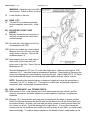
1
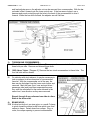
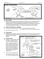
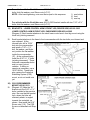
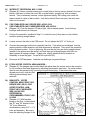
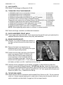
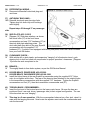
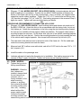
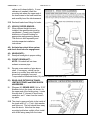
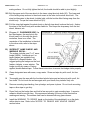
FORM #3260.04-110209 PRINTED IN U.S.A. PAGE 1 OF 20 Superlift 4” to 6”lift system for 1988- Newer GENERAL MOTORS FULL-SIZE ½ TON 4WD Trucks With 6 Hole Wheels (up to 7300 lb. GVWR) INSTALLATION INSTRUCTIONS INTRODUCTION Installation requires a professional mechanic. Prior to beginning, inspect the vehicles steering, driveline, and brake systems, paying close attention to the suspension link arms and bushings, anti-sway bars and bushings, tie rod ends, pitman arm, ball joints and wheel bearings. Also check the steering sector-to-frame and all suspension-to-frame attaching points for stress cracks. The overall vehicle must be in excellent working condition; repair or replace all worn parts. Read instructions several times before starting. Be sure you have all needed parts and know where they install. Read each step completely as you go. NOTES: Rear lift is performed first. The rear lift is sold separately and includes separate installation instructions. Speedometer reprogramming is necessary; refer to step 47. The device is sold separately and includes separate installation instructions. A special tool is required to load/unload the torsion bars (step 2). Other special tools are recommended to detach/attach the pitman/idler studs. Refer to the factory service manual. Front end realignment is necessary. Exhaust modification is necessary, refer to step 50. This system utilizes the stock torsion bars, which normally yield the best ride quality. But, if the “final product” ride and handling seem too soft, heavier Gross Vehicle Weight Rating (GVWR) bars can be installed. Generally, heavier torsion bars are only needed to compensate for the extra weight of a winch or snowplow, or when the truck is subjected to extreme off-road use. Also, wider tires and wheels proportionally increase the leverage on the bars, which results in lower ride height and a “spongier” ride. GM offers torsion bars with various rates that are heavier than stock. Your vehicle’s existing torsion bar rate can be identified by a 3-letter code stamped into the bars’ ends. The code is also on an adhesive tag wrapped around the bars. An arrow on diagrams indicates which direction is toward the front of the vehicle. A foot-pound torque reading is given in parenthesis ( ) after each appropriate fastener. Do not fabricate any components to gain additional suspension height. Prior to drilling or cutting, check behind the surface being worked on for any wires, lines, or hoses that could be damaged. After drilling, file smooth any burrs and sharp edges. FORM #3260.04-110209 PRINTED IN U.S.A. PAGE 2 OF 20 Prior to operating a torch or saw, protect any heat-sensitive components located in the immediate area by covering them with a water-saturated cloth. Most undercoating are flammable but can be extinguished using a water-filled spray bottle. Have a spray bottle and an ABC rated fire extinguisher on hand. Paint or undercoat all exposed metal surfaces. Prior to attaching components, be sure all mating surfaces are free of grit, grease, undercoating, etc. A factory service manual should be on hand for reference. Use the check-off box “” found at each step to help you keep your place. Two “” denotes that one check-off box is for the driver side and one is for the passenger side. Unless otherwise noted, always start with the driver side. PARTS LIST … The part number is stamped into each part or printed on an adhesive label. Identify each part and place the appropriate mounting hardware with it. PART NO DESCRIPTION NEW ATTACHING HARDWARE (Qty.- if more than one) (Qty.) FOUND IN HDWE. PACK 55-01-3260 ....... bracket, upper control arm’s .........(1) 9/16” x 3 ½” bolt ..................... 77-0001 front leg, driver side (1) 9/16” Nyloc nut (2) 1 7/8” sq. washer, 1/8” thick (2) 7/16” x 1” bolt (2) 7/16” Stover nut (4) 5/8” ID, 1/16” thick shim ......... 77-0005 1998-1992 models only (2) cam bolt.................................. 77-0008 55-02-3260 ....... bracket, upper control arm’s .........same as above ............................ 77-0001 front leg, passenger side 77-0005 77-0008 55-03-3205........ bracket, lower control arm’s .........(1) 5/8” x 4 ½” bolt ....................... 77-0005 front leg, driver side (1) 5/8” Nyloc nut (1) 7/16” x 1 ¼” bolt (1) 7/16” Nyloc nut (1) 7/16”, thick flat washer 55-04-3205........ bracket, lower control arm’s .........same as above ............................ 77-0005 front leg, passenger side 55-05-3205........ bracket, upper/lower control ........(2) 5/8” x 5 ½” bolt ....................... 77-0004 arm’s rear legs, driver side (2) 5/8” Nyloc nut (1) 9/16” x 3 ½” bolt (1) 9/16” Nyloc nut (2) 9/16” USS flat washer (4) 5/8” ID, 1/16” thick shim ......... 77-0005 55-06-3205........ bracket, upper/lower control ........same as above ............................ 77-0004 arm’s rear legs, passenger side 77-0005 55-03-3260........ crossmember, differential front .....(2) 9/16” x 4” bolt ......................... 77-0002 (2) 9/16” Nyloc nut 55-04-3260........ crossmember, differential rear...... .................................................... included FORM #3260.04-110209 PART NO PRINTED IN U.S.A. DESCRIPTION NEW ATTACHING HARDWARE (Qty.- if more than one) (Qty.) PAGE 3 OF 20 FOUND IN HDWE. PACK 55-05-3260 ....... kicker brace, driver side ............... (1) 7/16” x 1 ¼” bolt ......................77-0002 (1) 7/16” Nyloc nut (1) 7/16” flat washer (2) 3/8” Nyloc nut 55-06-3260 ....... kicker brace, passenger side ....... same as above .............................77-0002 55-11-3205 ....... centerlink ..................................... (2) 12mm Stover nut Gd. 8.8 ........77-0005 (2) 14mm Stover nut Gd. 8.8 tube thread lock compound 55-01-3213 ....... crossmember, CSS ...................... (2) 9/16” x 1 ½” bolt ......................77-0003 (2) 9/16” Nyloc nut 55-03-3214 ....... stabilizer link, CSS driver side ..... (2) 9/16” x 3” bolt ..........................77-0003 (2) 9/16” Nyloc nut (2) 9/16” USS flat washer (4) half bushing (2) sleeve 55-04-3214 ....... stabilizer link, CSS passenger ..... same as above .............................77-0003 side 55-12-3215 ....... skid plate...................................... (4) 7/16” x 1 ¼” bolt ......................77-0004 (4) 7/16” Stover nut (8) 7/16”, thick flat washer 55-10-3260 ....... (2) front brake hose bracket ......... (1) 3/8” x 1” bolt ............................77-0025 (1) 3/8” Nyloc nut (1) 3/8” SAE washer (1) 5/16” x 3/4” bolt (1) 5/16” SAE washer (1) 5/16” Stover nut differential vent hose extension ... 3 ½” long vent hose with coupler ..77-0005 extension travel limiting strap kit, . (2) #01-99265 strap ......................77-0021 rear axle (2) ½” X 1” bolt (2) ½” Nyloc nut (2) ½”, thick flat washer (2) cable tie 85113................ (2) shock absorber, front 85156................ (2) shock absorber, rear FORM #3260.04-110209 PART NO PRINTED IN U.S.A. DESCRIPTION NEW ATTACHING HARDWARE (Qty.- if more than one) (Qty.) PAGE 4 OF 20 FOUND IN HDWE. PACK NOTE: Your application will include only the #55-10-3205 OR #55-10-3210, not both 55-10-3205............. bracket, 2 bolt idler arm .................... (2) 7/16” x 2 ¾” bolt all 1988 through 1991 models, (2) 7/16” Stover nut some 1992 and 1993 models (2) 7/16”, thick flat washer OR 55-10-3210............. bracket, 3 bolt idler arm .................... (3) 7/16” x 2 ¾” bolt some 1992 and 1993 models, (3) 7/16” Stover nut all 1994 and newer models (3) 7/16”, thick flat washer NOTE: Your application will include only the #55-07-3260 OR #55-01-3265, not both. 55-07-3260............. (2) bracket, torsion bar crossmember (2) 7/16” x 5 ½” bolt All models except 1995 4-door (4) 7/16” x 4” bolt Yukon/Tahoe Short Wheel Base (6) 7/16” Stover nut (12) 7/16”, thick flat washer OR 55-01-3265............. (2) link, torsion bar crossmember ..... (2) 7/16” x 1 ½” bolt 1995 4-door Yukon/Tahoe (2) 7/16” Nyloc nut Short Wheel Base (2) 7/16” flat washer (2) 7/16” x 2 ¾” bolt (2) 7/16” Stover nut (2) 7/16”, thick flat washer (2) support cable (2) bushing half (2) sleeve FRONT PROCEDURE 1) PREPARE VEHICLE... Place vehicle in neutral. Raise front of vehicle with a jack and secure a jack stand beneath each frame rail, behind the lower control arms. Ease the frame down onto the stands, place transmission in low gear or “park”, and chock rear tires. Remove front tires. 2) UNLOADING THE TORSION BARS… WARNING: Be extremely careful when loading or unloading the torsion bars; there is a tremendous amount of stored energy in the bars. Keep your hands and body clear of the adjuster arm assembly and puller tool in case anything slips or breaks. NOTE: For safe removal / installation of the adjuster arms, a special puller tool is required. Because of the tremendous loads generated, a standard 2-jaw gear puller tool tends to bend down te crossmember “lips”, where it attaches, and pops out of place. If not found locally, this special puller tool is available from: Kent Moore Tool Group, Roseville, MI… PH: (800) 345-2233, or (313) 774-9500…#J-22517-C. [Diagram1] On either side, remove the torsion bar aligning screw. Apply light lubricating grease to the puller threads and the puller shaft-to-adjuster arm contact point. Position puller FORM #3260.04-110209 PRINTED IN U.S.A. PAGE 5 OF 20 and load adjuster arm so the adjuster nut can be removed from crossmember. With the bar unloaded, slide it forward onto the lower control arm. If the bar seems lodged, use a hammer and punch routed through the hole in the back of the crossmember to drive it forward. When the bar shifts forward, the adjuster arm will fall free. 3) TORSION BAR CROSSMEMBER… All models except 1995 4-door Yukon: The crossmember connects to the frame with three bolts per side. Remove and discard these bolts. OR 1995 4-door Yukon: [Diagram 2] Remove the two stock crossmember-to-frame links. The four link bolts will be reused. On vehicles with stock exhaust, it may be necessary to jack-up exhaust to allow clearance for crossmember removal. With the crossmember out of the way, the bars can be dislodged from the lower control arms and removed. Mark the bars (front / rear end and driver / passenger side) and keep them seperated because they must be reinstalled on the same side and in the same front / rear direction as they were removed. Steps 4 through 8 are performed one side at a time. Start at the driver side. 4) BRAKE HOSE… At driver’s side front, use vise-grips, or a small C-clamp, to pinch closed the rubber brake hose which runs from caliper-to-frame. Detach hose from caliper. Plug, or cover, the caliper opening to prevent contamination. FORM #3260.04-110209 PRINTED IN U.S.A. PAGE 6 OF 20 5) AXLE SHAFT… Remove the 6 bolts that attach CV axle flange to differential. 6) INNER TIE ROD… [Diagram 3] The stock centerlink is shown. Using special puller tool (refer to factory service manual), detach inner tie rod ends from centerlink. NOTE: Do not hammer on linkage or use a pickle fork or wedge type tool to dislodge because damage may occur. 7) ANTI-SWAY BAR… Remove both anti-sway bar drop links, which connect bar body-to-lower control arms. the link nuts, accessed through the bottom of the arms, are somewhat restricted. It may be necessary to detach bar at frame first. 8) CONTROL ARM / HUB ASEMBLY REMOVAL… Position a floor jack under the hub assembly. Remove upper and lower control assembly to floor. NOTE: Vehicles equipped with 4 wheel anti-lock brakes have a wiring harness at each front wheel that runs from the frame, along the control arm, and down to the outer axle. Remove mounting bolt, then unplug connector as shown [Diagram 4]. A new mounting hole is drilled in step 30. Perform Steps 4 through 8 on passenger side. 9) DRIVESHAFT… Detach front driveshaft at differential and secure it out of the way. 10) SKID PLATE… Remove differential skid plate (if so equipped). 11) DIFFERENTIAL WIRING, HOSE… Unplug differential wiring harness and vent hose. FORM #3260.04-110209 PRINTED IN U.S.A. PAGE 7 OF 20 12) TRIM FRAME… [Diagram 5] Place a jack under the differential. Remove the bolts (2 total) that attach the rear of the differential to the lower control arm / differential mounts on the driver and passenger sides. With the two front upper differential bolts still attached, raise the jack to pivot the differential upward and out of the way. With a torch, trim off the driver side mounting bracket shown as Section “A”. This allows the differential to be lowered. 13) REMOVE DIFFERENTIAL ASSEMBLY… Now remove the reamaining bolts: 1 bolt: at top of differential on driver side. 1 bolt: upper axle mount-to-frame at passenger side. Now lower assembly to the floor. 14) TRIM FRAME… [Diagram 5] On both sides, use a torh to trim Section “B” from the stock lower control arm / differential mount as shown (represented as dotted lines). This allows clearance for the differential in the relocated position. 15) TRAVEL STOPS… [Diagram 6] On both sides, unbolt the rubber compression travel stops from their stock position. These stops will be reused. With a torch, carefully trim the steel, frame mounted brackets from the frame as shown. Care must be taken to cut these brackets as close to the frame as possible to allow clearance for the Superlift relocation hardware that is installed later. Grind clean all cutting slag from the trimming performed in steps 12, 14, and 15, and lightly coat all FORM #3260.04-110209 PRINTED IN U.S.A. PAGE 8 OF 20 bare metal surfaces with a spray-on rust inhibitor. 16) CENTERLINK REMOVAL… Using special puller tool (refer to factory service manual), detach center link from pitman and idler arm studs. NOTE: Do not use a pickle fork or wedge type tool because seal or bushing damage may occur. Also, do not hammer on pitman arm, shaft, or puller because damage to arm / steering gear may result. 17) ANTI-SWAY BAR… [Diagram 7] Detach antisway bar body from frame. Reinstall with ends inverted – or switched – so that the bar body steps down instead of up. Tighten sway barto-frame bolts (12). 18) IDLER ARM SPACER… [Diagram 8] The spacer fits between the idler arm and its frame mounting point. The arm is accessed by partially removing the passenger side inner fender. NOTE: On vehicles equipped with an airbag, the airbag sensor is lcated on the side of the frame near the holes for the idler arm bolts. USE CAUTION! If struck, the airbag may deploy or malfunction. FORM #3260.04-110209 PRINTED IN U.S.A. PAGE 9 OF 20 For vehicles with the 3-bolt idler arm, #55-10-3210 bracket installs with three 7/16” x 2 ¾” bolts, thick flat washers, and Stover nuts (LC 57). NOTE: After hand tightening, nuts must be torqued in this sequence: 1) rear bottom 2) front 3) rear top OR For vehicles with the 2-bolt idler arm, #55-10-3205 bracket installs with two 7/16” x 2 ¾” bolts, thick flat washers, and Stover nuts (LC 57). 19) BRACKETS: LOWER CONTROL ARM’S FRONT LEG, DRIVER SIDE, #55-03-3205 LOWER CONTROL ARM’S FRONT LEG, PASSENGER SIDE #55-04-3205 [Diagram 9] Each bracket attaches to the stock lower control arm’s front leg mount using the stock bolt, pointing rearward. Each bracket attaches to the frame’s front crossmember with the two bolts; one inboard and one outboard. At the inboard hole, drill a 15/32” hole into the crossmember and install a 7/16” x 1 ¼” bolt, flat washer, and Nyloc nut; position the flat washer inside the crossmember (37). At the outboard holes, install the 9/16” X 1 ½” bolts (pointing downward). These outboard cossmember holes exist on most, but not vehicles. If drilling or reaming is necessary, use a 19/32” drill bit. These bolts also capture the Centerlink Stabilizing System (CSS) mount, so do not install nuts yet. 20) CSS CROSSMEMBER MOUNT, #55-01-3213 [Diagram 10] Mate the “01” bracket onto the 9/16” x 1 ½” bolts, installed in the previous step. Be sure that the bracket face, where the links will ultimately attach, is angled towards the centerlink, as shown. Now install the 9/16” Stover nuts (110). The CSS liks are not attached until Step 22. FORM #3260.04-110209 PRINTED IN U.S.A. PAGE 10 OF 20 21) SUPERLIFT CENTERLINK, #55-11-3205 [Diagram 8] Unless a special seating tool is used (refer to factory service manual), the new pitman / idler arm-to-center link nuts (40) must be initially “snugged up” with an impact wrench. This is necessary because, unless tightened rapidly, the locking nuts cause the tapered studs to rotate in their sockets. Use the furnished 14mm lock nuts; the stock nuts must not be reused. 22) CSS STABILIZER LINK, DRIVER SIDE, #55-03-3214 CSS STABILIZER LINK, PASSENGER SIDE, #55-04-3214 [Diagram 10] Coat the sleeves’ OD with a light, Lithium based grease. Insert link eye bushings and sleeves into link eyes. Position the centerlink, installed in Step 21, so that the tires (if they were on the vehicle) would be pointing straight ahead. Loosely connect the links to the CSS mount. Do not tighten the 9/16” x 3” bolts yet. Connect the passenger side link-to-centerlink tab first. If the holes are misaligned, turn the steering wheel in either direction until hole alignment is achieved. Then return the centerlink to the centered position. Prior to tightening, be sure that the links are facing straight ahead (parallel to the pitman and idler arms), and that their eye bushing flanges seat flush (no gaps) against all mating surfaces. If gaps exist, slightly bend the tabs or bracket as necessary to close the gaps. Torque all link eye bolts (65). Re-torque all CSS hardware. Lubricate eye bushings via grease fittings. 23) STOCK UPPER CONTROL ARM HANGERS… [Diagram 6] The hangers have slotted holes that allow them the control arms to be moved in or out to achieve front end alignment by adjusting the eccentric cam bolts. On some models, the slot must be opened-up by knocking-out a perforated plug. If the vehicle has been aligned previously, odds are that the plugs have already been removed. 24) BRACKETS: UPPER CONTROL ARM, FRONT LEG, DRIVER SIDE, #55-01-3260 UPPER CONTROL ARM, FRONT LEG, PASSENGER SIDE, #55-02-3260 DIFFERENTIAL CROSSMEMBER, FRONT, #5503-3260 [Diagram 11] With brackets laying on the floor, loosely attach the “01” and “02” bracket to the “03” (front differential crossmember) using 7/16” x 1 ¼” bolts and hardware. Be sure to have the attaching flanges of the FORM #3260.04-110209 PRINTED IN U.S.A. PAGE 11 OF 20 crossmember to the front side of the “01” and “02” brackets. do not tighten the 7/16” bolts at this time. Position the 3-piece crossmember / bracket assembly up to the frame as shown and align the “01” and “02” brackets into the strock upper control arm mounts. Connect the two using 9/16” x 3 ½” bolts and Nyloc nuts with 1 7/8” square washers positioned on both sides of the 9/16” bolts. The square washers are used to center the bolts in their slotted holes. Insert factory bolts through the crossmember’s upper tabs where they mate to the stock differential mounts. These will be tightened later. 25) DIFFERENTIAL-TO-FRONT CROSSMEMBER… [Diagram 12] Raise the differential into position with a floor jack. Insert two 9/16” x 4” bolts into the differential-to-front crossmember mounts; hand tighten only. This differential mounting hardware is tightened later. Keep the jack “loaded” into position. The differential’s rear crossmember is installed in Step 29. Steps 26 through 28 are performed one side at a time. Start at driver side. 26) BRACKET: UPPER / LOWER CONTROL ARM’S REAR LEGS, DRIVER SIDE, #5505-3205 [Diagram 11] Locate and check fit the bracket. Now bolt the bracket-to-frame at the stock lower control arm mounting point. Use furnished 5/8” x 5 ½” bolt, pointing rearward. Do not install Nyloc nut at this time. At the top mounting point, with the slotted holes, insert the furnished 9/16” x 3 ½” bolt and Nyloc nut, pointing forward. Place the USS flat washers behind te bolt head and nut. Hand tighten only. NOTE: There may be a clearance problem in the area where the travel stop was cut from the frame. If so, heat and dimple the frame inward to gain the needed clearance. FORM #3260.04-110209 PRINTED IN U.S.A. PAGE 12 OF 20 At the bracket’s top mounting points, shimming is required; see next step. 27) SHIMMING BRACKETS… [Diagram 13] Due to manufacturing tolerances, there may be slight gaps between the bracket and the stock upper control arm mounting ears. If gaps exist, bridge gaps with the shims. Hradware Pack 77-0005 contains 16 thin shims. There should be enough shims to cover all four of the Superlift bracket-to-stock upper control arms attaching points. 28) BUMP-STOP… [Diagram 14] In order to clear the shock absorber, grind the front / outside corner of the stock rubber compression travel bump-stop to match the radius of its mounting pad on #55-053205. Then attach bump stop as shown. Repeat steps 26 through 28 on the passenger side. 29) DIFFERENTIAL CROSSMEMBER, REAR, #5504-3260 [Diagram 12] Reposition the jack to under the rear end of the differential. Raise the jack to rotate the differential upward as high as it will go. Position the rear crossmember by mating it onto the two 5/8” bolts protruding through the stock rear control arm mounts as shown. Once the crossmember is in place install the two 5/8” Nyloc nuts; hand tighten only. Lower the jack and differential until the rear attachment points align, then install the original mounting bolts (112). Steps 30 through 37 are performed one side at a time. Start at the driver side. 30) REHANGING CONTROL ARMS… With the control arm assembly on a floor jack, raise it into position. Install 5/8” x 5 ½” bolt and Nyloc nut at the lower control arm / rear leg attaching point. This bolt points rearward and will also capture the bottom hole of the diffrential’s rear crossmember. Use a 5/8” x 4 ½” bolt, pointing forward, to connect front leg of lower control arm. Now mate the upper control arm to the Superlift bracket with the factory eccentric cam bolts. In applications with the two-bolt idler, the eccentric cam bolts are supplied. Be sure that the anti-sway bar body is pivoted down so it is below the upper control arm’s front leg. NOTE: 4-wheel anti-lock brakes [Diagram 4] – The wiring harness, disconnected in Step 8, must be relocated lower on the frame. Drill one new hole as shown, and reconnect harness. FORM #3260.04-110209 PRINTED IN U.S.A. PAGE 13 OF 20 31) AXLE SHAFTS… Attach CV axle flange-to-differential (LC 60). 32) TORQUE BOLTS IN THIS SEQUENCE… 1) differential’s front crossmember-to-frame……………………… 2 bolts (112) 2) diferential-to-front crossmember………………………………... 2 bolts (82) 3) differential-to-rear crossmember………………………………... 2 bolts (82) 4) rear crossmember’s top bolts-to”05” and “06” brackets……… 2 bolts (112) 5) rear lower control arm legs-to-Superlift brackets………………2 bolts (112) These bolts also capture the two bottom holes on the differential’s rear crossmember. 6) front lower control arm legs-to-Superlift brackets…………….. 2 bolts (112) 7) Superlift brackets-to-stock upper control arm mounts……….. 4 bolts (82) 8) front crossmember-to-“01” and “02” brackets…………………. 4 bolts (57) 9) cam bolts at upper control arm-to-Superlift brackets…………. 4 bolts (75-90) NOTE: Before tightening, adjust cams to a neutral, or centered position. Check axle flange, centerlink, and diferential clearances. 33) SHOCK ABSORBER, FRONT, #85101 Torque upper and lower bolts (48). Cycle suspension through full travel cycle and check for adequate clearance between shock, bump stop, and brake hose. 34) BRAKE HOSE BRACKET… [Diagram 15] Locate the brake hose retainer on the frame rail and diconnect the brake hose from the clip. Remove the brake hose bracket from its attachment point on top of the factory front upper control arm leg mounting bracket. Position the short side (one hole) of the Superlift brake hose bracket (SL# 55-10-3260) to the bottom side of the factory upper control arm mount and align so that it is parallel with the center of the upper control arm. Secure the bracket with the supplied 3/8” x 1” bolt, washer (at bolt head), and Nyloc nut (30). Install the bolt from the top. Carefully re-form (straighten-out) the bends, as needed, to allow the factory brake line bracket to mate with the Superlift bracket. DO NOT kink the line. Attach the factory brake line bracket to the Superlift brake line bracket, align the bolt hole with the upper hole and the tab with the lower hole. Secure with the supplied 5/16” x 3/4” bolt, washer (at bolt head), and Stover nut (200 In. Lbs.). Install bolt from the top. 35) TIE ROD END, INNER… Attach inner tie rod end-to-centerlink with furnished 12mm Stover nut (40). Do not reuse the stock nut. Unless a special seating tool is used (refer to factory service manual), the tie rod end-to-centerlink must be initially “snugged up” with an impact wrench. FORM #3260.04-110209 PRINTED IN U.S.A. PAGE 14 OF 20 36) DIFFERENTIAL WIRING… Reconnect differential’s electrical plug and vent hose. 37) ANTI-SWAY BAR LINKS… Reinstall stock anti-sway bar drop links. Tighten drop link bolts only until bushings swell slightly. Repeat steps 30 through 37 on passenger side. 38) SKID PLATE, #55-12-3215 [Diagram 16] Skid plate attaches, as shown, with stock bolts (57) at the front frame crossmember and new 7/16” hardware (57) at the stock skid plate attaching points. The stock skid plate then bolts to the rear Superlift crossmember with the supplied 7/16” hardware (57). If vehicle is not equipped with factory skid plate, order GM Part #15538494 from your local GM dealer. 39) CLEARANCE CHECK… With vehicle still on jack stands, and suspension “hanging” at full extension travel, cycle steering lock-to-lock and check all components for proper operation / clearances. [Diagram 15] shows the work completed so far. 40) BRAKES… Thoroughly bleed air from brake system, as per the GM Service Manual. 41) KICKER BRACE, DRIVER SIDE, #55-05-3260 KICKER BRACE, PASSENGER SIDE, #55-06-3260 Install the kicker brace at the rear Superlift crossmember using the supplied 5/16” Nyloc nuts; do not tighten at this time. The rear of the brace is then attached to the existing holes in the transmission crossmember with the supplied 7/16” hardware. Tighten the Superlift crossmember end first (57), then the transmission crossmember end (57). 42) TORSION BARS / CROSSMEMBER… Insert the front end of the torsion bars into the lower control arms. Be sure the bars are positioned (front / rear end, driver / passenger side) in their original configuration. The rear of the bar ends are now “hanging”. This step is a 2-man operation. With the crossmember balanced on a floor jack, raise it to mate with the hanging bar ends. Now locate the adjuster arms inside the crossmember and onto the bar ends. FORM #3260.04-110209 PRINTED IN U.S.A. PAGE 15 OF 20 TORSION BAR CROSSMEMBER BRACKET, #55-07-3205 [Diagram 17] ALL MODELS EXCEPT 1995 4-DOOR YUKON: Lubricate adjuster bolt and puller threads prior to installation. Position the two #55-07-3205 brackets in between the bottom of the frame rails and top of the crossmember. Invert, as shown, the stamped steel straps that cap the rubber insulators. Tighten the 7/16” x 5 ½” center bolts and Stover nuts (18) then the outer edge 7/16” x 4” bolts (57). Bar loading sequence is the reverseof Step 2; again, be careful. Tighten until arms are just clearing nut blocks. OR TORSION BAR CROSSMEMBER-TO-FRAME LINK, #55-01-3265 [Diagram 18] 1995 4-DOOR YUKON: Insert bushing halves and sleeves into each end of the #55-01-3265 link. Attach the links to the crossmember with the factory bolts, but do not fully tighten yet. Attach the crossmember to the links using the stock bolts pointing forward; the nuts are not installed until the support cables are attached. The support cables have a mounting bracket on each end. On the driver side, slip one of the cable’s mounting brackets (either end will do) onto the bolt. Position the mounting bracket so it points towards the front of the vehicle and is angled upwards. Now torque both bottom and top link bolts (82). The other end of the cable mounts to the bottom side of the frame rail. Pull the cable tight, locate the mounting bracket and mark the frame. Measure back 3/8” to allow some cable slack, and drill a 15/32” hole for the new 7/16” x 1 ½” bolt; torque to (41). Install the cable on the passenger side. Lubricate adjuster bolt and puller threads prior to installation. Bar loading sequence is the reverse of Step 2; again, be careful. Tighten until arms are just clearing nut blocks. 43) TIRES / WHEELS... Tighten the lug nuts to factory specifications. WARNING: When the tires / wheels are installed, always check for and remove any corrosion, dirt, or foreign material on the wheel mounting surface, or anything that contacts the wheel mounting surface (hub, rotor, etc.). Installing wheels without the proper metal-to-metal contact at the wheel mounting surfaces can cause the lug nuts to loosen and the wheel to come off while the vehicle is in motion. FORM #3260.04-110209 PRINTED IN U.S.A. PAGE 16 OF 20 WARNING: Retighten lug nuts at 500 miles after any wheel change, or anytime the lug nuts are loosened. Failure to do so could cause wheels to come off while vehicle is in motion. Lower vehicle to the floor. 44) REAR LIFT... The rear lift is purchased separately and has separate instructions. Install now. 45) ADJUSTING FRONT RIDE HEIGHT... Manually bounce the front and rear of vehicle to normalize the torsion bars and leaf springs. On each side, fully tighten the LCA-tocrossmember bolts (156). Position the vehicle on a level surface. Measure from the LCA front pivot bolt center down to the floor. Record this as Measurement “A”. Now measure from the inside edge of the knuckle (at the lower ball joint boss) down to the floor. Record this as Measurement “B”. Subtract Measurement “B” from “A” for the ride height figure. Minimum ride height is 3.08”; maximum is 5.0”. Ideal ride height is somewhere in between. Raise height by tightening the torsion bar adjusting bolt; lower height by loosening the bolt. Adjust height 3/8” to 1/2” above the final desired ride height, since the bars will settle slightly after the vehicle is driven. NOTE: Exceeding the stated minimum or maximum heights will cause the suspension to continually “top out” or “bottom out”. This results in a harsh ride, accelerated suspension component wear, and possibly component failure. 46) FINAL CLEARANCE and TORQUE CHECK... With vehicle on floor, cycle steering lock-to-lock and inspect the tires / wheels, and the steering, suspension, and brake systems for proper operation, tightness, and adequate clearance. [Diagram 19] If stock wheels are being used (or wheels with the same or greater positive offset), the distance between the tire side wall and the brake hose will be minimal and must be checked closely. Normally, the hose and tire will be closest to making contact when the tire / wheel is in a turn. Cycle the steering left-to-right full-lock. If at any point during the turning cycle the tire and hose come within one inch or closer of each other, you must modify these accordingly. To achieve desired clearance, first bend the hose’s metal leader (at the FORM #3260.04-110209 PRINTED IN U.S.A. caliper end) inboard slightly. If more clearance is needed, locate the mounting tab where the upper end of the hose mates to the hard metal line, and carefully bend the tab downward. Recheck brake hose fittings for leaks. 47) VEHICLE SPEED SENSOR… When different height tires are installed, the speedometer must be recalibrated. Consult your Superlift distributor or Superlift catalog for appropriate reprogramming device. The device is sold separately and includes separate installation instructions. 48) Activate four wheel drive system and check front hubs for engagement 49) HEADLIGHTS... Readjust headlights to proper setting. 50) FRONT DRIVESHAFT… NOTE: Driveshaft will not clear exhaust crossover pipe. Reroute a new section of pipe above shaft. If necessary, vehicle can be driven to a muffler shop with the front drive shaft completely removed. Torque shaft-to-differential bolts (15); shaft-to-transfer case bolts (74). 51) REAR AXLE EXTENSION TRAVEL LIMITING STRAPS and REAR SHOCK ABSORBERS… [Diagram 20, DRIVER SIDE] Drill a 17/32” diameter hole in the tower, as shown, for the upper end of the limiting strap. Locate this new hole ½” inboard of shock body centerline, and 1” down from the tower’s top plate. The strap’s upper end bolts to the inside of the tower with a ½” x 1” bolt, thick washer, and Nyloc nut. The bolt should face away from the shock. Note that the strapmounting buckle has a slight offset; install with offset facing away from the tower- PAGE 17 OF 20 FORM #3260.04-110209 PRINTED IN U.S.A. PAGE 18 OF 20 mating surface. Do not fully tighten the bolt; the buckle should be able to pivot slightly. Bolt the upper end of the new shock to the tower using the stock bolts (20). The lower end of the limiting strap anchors to the shock mount at the axle via the stock shock bolt. The strap buckle mates to the wheel (outside) side, with the buckle offset facing away from the shock body. Torque the lower shock bolt (81). Pull the strap tight against the shock body so that all strap slack is above the body. Anchor the strap to the shock body with another cable tie. This keeps the strap away from the tire / wheel, exhaust, etc. [Diagram 21, PASSENGER SIDE] As per the diagram, the new hole in the shock tower is in line with the shock centerline, there is no offset. The remainder of the installation is identical to the driver side; refer to the steps above. 52) SUPERLIFT NAME BADGE AND WARNING DECAL... The system includes one 2” x 5” name badge (#0034). Additional and / or larger badges are available from Superlift or a Superlift dealer. We suggest putting the badges on the front fenders, tailgate, or rear window. The badge mounts by means of factory applied, double-backed tape. Follow these instructions to ensure that badge sticks properly: Clean designated area with warm, soapy water. Rinse and wipe dry with a soft, lint free towel. Thoroughly prep the area with the furnished alcohol wipe pad and wipe dry with a soft, lint free towel. Do not touch the surface again with your hands; they transfer body oils. Remove mounting tape backing, line up badge, and press in place. Do not touch mounting tape or allow tape to get dirty. Press firmly on the badge face and hold a few seconds to seat mounting tape. A superior adhesive bond forms over time. We recommend allowing 24 hours of cure time before washing and waxing. The emblem itself can be cleaned with any glass cleaner. Install the WARNING TO DRIVER decal on the inside of the windshield, or on the dash, within driver’s view. Refer to the “NOTICE TO DEALER AND VEHICLE OWNER” section below. FORM #3260.04-110209 PRINTED IN U.S.A. PAGE 19 OF 20 53) ALIGNMENT... Realign vehicle to factory specifications. Record the ride height measurement at time of alignment. If, in the future the torsion bars settle excessively, alignment can be restored by adjusting-up the bars to their original ride height. Limited Lifetime Warranty / Warnings ® Your Superlift product is covered by the Limited Warranty explained below that gives you specific legal rights. This ® ® limited warranty is the only warranty Superlift makes in connection with your product purchase. Superlift neither assumes nor authorizes any retailer or other person or entity to assume for it any other obligation or liability in connection with this product or limited warranty. ® What is covered? Subject to the terms below, Superlift will repair or replace its products found defective in materials or workmanship for so long as the original purchaser owns the vehicle on which the product was originally ® ® installed. Your warrantor is LKI Enterprises, Inc. d/b/a Superlift Suspension Systems (“Superlift ”). ® What is not covered? Your Superlift Limited Warranty does not cover products, parts or vehicles Superlift® determines to have been damaged by or subjected to: • Alteration, modification or failure to maintain. • Normal wear and tear (bushings, tie-rod ends, etc.). Scratches or defects in product finishes (powdercoating, plating, etc.), • Damage to or resulting from vehicle’s electronic stability system, related components or other vehicle systems. • Racing or other vehicle competitions or contests. Accidents, impact by rocks, trees, obstacles or other aspects of the environment. • Theft, vandalism or other intentional damage. Remedy Limited to Repair / Replacement. The exclusive remedy provided hereunder shall, upon Superlift’s inspection and at Superlift’s option, be either repair or replacement of product or parts covered under this Limited ® Warranty. Customers requesting warranty consideration should contact Superlift by phone (1-800-551-4955) to obtain a Returned Goods Authorization number. All removal, shipping and installation costs are customer’s responsibility. ® If a replacement part is needed before the Superlift part in question can be returned, you must first purchase the replacement part. Then, if the part in question is deemed warrantable, you will be credited / refunded. Other Limitations - Exclusion of Damages - Your Rights Under State Law ® ® • Neither Superlift nor your independent Superlift dealer are responsible for any time loss, rental costs, or for any incidental, consequential or other damages you may have. • This Limited Warranty gives you specific rights. You may also have other rights that vary from state to state. For example, while all implied warranties are disclaimed herein, any implied warranty required by law is limited to the terms of our Limited Lifetime Warranty as described above. Some states do not allow limitations of how long an implied warranty lasts and / or do not allow the exclusion or limitation of incidental or consequential damages, so the limitations and exclusions herein may not apply to you. Important Product Use and Safety Information / Warnings As a general rule, the taller a vehicle is, the easier it will roll over. Offset, as much as possible, what is lost in rollover resistance by increasing tire track width. In other words, go “wide” as you go “tall”. Many sportsmen remove their mud tires after hunting season and install ones more appropriate for street driving; always use as wide a tire and wheel combination as feasible to enhance vehicle stability. We strongly recommend, because of rollover possibility, that the vehicle be equipped with a functional roll bar and cage system. Seat belts and shoulder harnesses should be worn at all times. Avoid situations where a side rollover may occur. Generally, braking performance and capabilities are decreased when significantly larger / heavier tires and wheels are used. Take this into consideration while driving. Also, changing axle gear ratios or using tires that are taller or shorter than factory height will cause an erroneous speedometer reading. On vehicles equipped with an electronic speedometer, the speed signal impacts other important functions as well. Speedometer recalibration for both mechanical and electronic types is highly recommended. FORM #3260.04-110209 PRINTED IN U.S.A. PAGE 20 OF 20 Do not add, alter, or fabricate any factory or aftermarket parts to increase vehicle height over the intended height of the Superlift product purchased. Mixing component brands is not recommended. ® ® All Superlift material is copyrighted. All images found in this catalog and in any Superlift marketing forums are the ® sole property of or licensed to Superlift . Any reproduction of said materials, in part or in whole, with out the express ® ® written permission of Superlift is strictly forbidden. Superlift , Rockrunner™, Swamprunner™, Superide™, Superide ® SS™ and SSR™, Black Diamond , XCL™, X2™ Super Trac™, Torque Max™, Torque Max SS™, eXtreme Ring™, Rail Wrap™, Bullet Proof Brake Hose™, TruSpeed™, Frame Integrated Technology™, F.I.T. Series™ and Rock ™ ® ® Fink are registered trademarks of Superlift Suspension Systems. Superlift Suspension Systems is a Division of Bret Lovett’s Lift Kits Incorporated. SUPERLIFT SUSPENSION SYSTEMS 300 Huey Lenard Loop Rd. West Monroe, Louisiana 71292 Phone: (318) 397-3000 Sales / Tech: 1-800-551-4955 FAX: (318) 397-3040 www.superlift.com