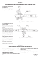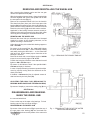
1
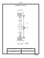
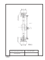
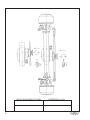
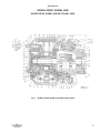
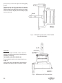
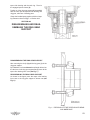
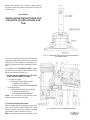
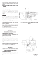
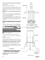
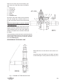
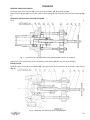
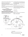
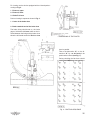
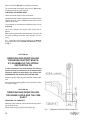
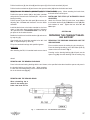
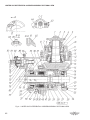
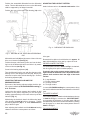
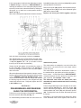
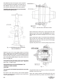
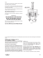
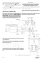
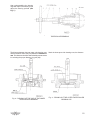
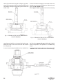
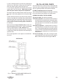
REPAIR MANUAL
DRIVEN FRONT AXLE
MT14/MT17 SERIES
MARMON-HERRINGTON ALL-WHEEL DRIVE
13001 Magisterial Drive • Louisville, KY 40223
(502) 253-0277 • (800) 227-0727 • Fax (502) 253-0317
E-mail: [email protected]
1
SECTION 202
SECTION
CONTENTS
SECTION NO.
PAGE
FORWORD...........................................................................................................................203
5
DRAWING OF THE DRIVEN FRONT AXLES TYPE MH MT14/MT17................................204
6
TECHNICAL DATA..............................................................................................................205
9
TORQUE RATINGS.............................................................................................................206
13
ADJUSTMENT DATA...........................................................................................................207
15
GENERAL SERVICE INSTRUCTIONS...............................................................................209
16
WHEEL DRIVE; WHEEL HUB.....................................................................................
16
KNUCKLE HOUSING..................................................................................................
16
WHEEL BRAKE...........................................................................................................
16
DIFFERENTIAL CARRIER HEAD...............................................................................
16
GENERAL INSTRUCTIONS........................................................................................
16
WHEEL DRIVE, WHEEL HUB
WHEEL DRIVE, WHEEL HUB SECTIONAL VIEW.....................................................210
17
PARTS OF THE WHEEL DRIVE, WHEEL HUB..........................................................211
18
REMOVING AND REINSTALLING THE WHEEL DISK..............................................212
19
REMOVING AND REINSTALLING THE BRAKE DRUM............................................213
19
REMOVING AND REINSTALLING THE END-COVER...............................................214
19
REMOVING AND REINSTALLING THE PINION
CARRIER, ADJUSTING THE AXLE-SHAFT CLEARANCE.......................................220
19
DISASSEMBLING AND REASSEMBLING THE PLANETARY GEAR.......................221
20
REMOVING AND REINSTALLING THE SUN GEAR..................................................222
20
REMOVING AND REINSTALLING THE WHEEL HUB...............................................223
21
ADJUSTMENT OF AXIAL PLAY.................................................................................224
21
DISASSEMBLING AND REASSEMBLING THE RING GEAR SUPPORT.................225
23
INSTALLATION INSTRUCTIONS FOR PARTS OF ANTI-LOCKING SYSTEM.........229
24
2
SECTION
SECTION NO.
PAGE
REMOVING AND REINSTALLING THE TIE-ROD,
ADJUSTING THE TOE-IN AND THE WHEEL TURN ANGLES..............................241
25
REPAIRING TIE ROD..................................................................................................242
26
DISASSEMBLING AND REASSEMBLING THE KNUCKLE HOUSING
AND THE SPINDLE..................................................................................................243
27
DISASSEMBLING AND REASSEMBLING THE DOUBLE-JOINT
AND THE KNUCKLE SUPPORT.............................................................................244
27
REMOVING AND REINSTALLING ADJUSTING, THE STEER ARMS,
THE BRAKE CHAMBER HOLDER AND THE TIE-ROD ARMS.............................245
28
ASSEMBLING THE DOUBLE-JOINT (REPLACING THE AXLE-SHAFT).................246
29
REMOVING AND REINSTALLING THE INNER BEARING
AND FASTENERS OF THE SPINDLE TRUNNION.................................................247
31
FRONT AXLE HOUSING
FRONT WHEEL BRAKE
DRAWING OF THE FRONT WHEEL BRAKE.............................................................260
33
PARTS OF THE FRONT WHEEL BRAKE..................................................................261
33
REMOVING AND REINSTALLING THE BRAKE SHOES..........................................262
34
REPAIRING THE BRAKE SHOES AND THE BRAKE DRUM....................................263
34
REMOVING AND REINSTALLING THE BRAKE BRACKET,
ASSEMBLING THE SPRING SUPPORTING PIN...................................................264
36
REMOVING AND INSTALLATION OF THE BRAKE LEVER
AND THE CAMSHAFT.............................................................................................265
37
REPAIRING THE CAMSHAFT BEARING SUPPORT.................................................266
37
MANUAL SLACK ADJUSTER AND ITS ASSEMBLING............................................267
39
AUTOMATIC SLACK ADJUSTER...............................................................................268
39
DIFFERENTIAL CARRIER ASSEMBLY
DIFFERENTIAL CARRIER ASSEMBLY DIFFERENTIAL
SECTIONAL VIEW...................................................................................................310
41
PARTS OF THE DIFFERENTIAL CARRIER ASSEMBLY...........................................311
43
REMOVING AND REINSTALLING THE DIFFERENTIAL
CARRIER ASSEMBLY.............................................................................................312
43
REMOVING AND REINSTALLING THE COMPANION FLANGE
AND THE COVER....................................................................................................313
43
REMOVING AND REINSTALLING THE DIFFERENTIAL,
ADJUSTING THE BACKLASH AND THE CONTACT PATTERN...........................314
45
3
SECTION
SECTION NO.
PAGE
DISASSEMBLING AND REASSEMBLING THE DIFFERENTIAL..............................315
47
DISASSEMBLING AND REASSEMBLING THE BEARING CAGE,
ADJUSTING THE CENTER DISTANCE..................................................................316
49
DISASSEMBLING AND REASSEMBLING THE BEARING CAGE............................317
50
OIL FILL-UP, RUN, CHECK.................................................................................................395
53
4
SECTION 203
FOREWORD
This publication “GENERAL REPAIR INSTRUCTIONS” was prepared for workshops and contains all the necessary assembly instructions
as well as data to be checked and adjusted during repair, with the knowledge of which repair
and adjustment of the MARMON-HERRINGTON
MT14/MT17 type driven front axles.
For technical data on the specific type versions of
the M-H MT14/MT17 type driven front axles refer to
the publication “TECHNICAL DATA”, while for the
spare parts of that “PARTS CATALOG” grouped
according to the Type.
The “GENERAL REPAIR INSTRUCTIONS” contain sections divided into the technical data and the
service instructions of the axle. The sections of the
service instructions contain the disassembly and
reassembly operations of the individual assembly
unit, stating the special tools to be used.
The serial numbers of the figures are started
from the beginning in each section. The item
numbers of the figures for an assembly unit are
referred to in each section dealing with the assembly procedures.
The manufacturer shall not be liable for warranty claims on damages resulting from negligence of the general service practice required
for normal service operations but not contained
in this Manual.
For replacing assembly units or individual parts use
ONLY genuine M-H MT14/MT17 made products.
RIGHTS FOR ALTERATIONS RESERVED!
MARMON-HERRINGTON COMPANY
13001 MAGISTERIAL DRIVE
LOUISVILLE, KY 40245
TEL.: 502-253-0277 FAX: 502-253-0317
5
SECTION 204
DRAWINGS OF AXLES
6
DRIVE PINION HAND OF SPIRAL
HUB PILOTED WHEEL
R (bal-right-links)
DRIVE PINION HAND OF SPIRAL
R (bal-right-links)
BALL SEAT WHEEL
7
8
DRIVE PINION HAND OF SPIRAL
DIFFERENTIAL LOCK
SECTION 205
TECHNICAL DATA
DESCRIPTION
UNITS
TYPE
MT14/MT17
SYSTEM:
The reduction of the driven and steered front axle is of two-stage design. The reduction is accomplished by a
pinion and ring gear set in the carrier and by spur planetary gearing in the wheel hub.
DIMENSIONS:
WHEEL TRACK
mm
a./ Rubber tire
2035*
16.5 x 22.5*
b./ Rolling radius
mm
540
c./ Sinking depth
mm
168.1*
Max. Width
mm
2480*
For detailed technical data marked by asterisk (*) at the type versions required by one orderer refer to publication
“TECHNICAL DATA” related to the type versions.
9
TECHNICAL DATA
DESCRIPTION
UNITS
205
TYPE
MT14/MT17
RATIOS:
Ring gear/pinion
27/22 - 29/13 *
Planetary gear
64/26 + 1 = 3.461
Total ratio
4.248 - 7.720 *
Differential lock *
GENERAL DATA:
Camber
1°
Knuckle pin inclination
7°
Inner wheel turn angle
max. 40°
Rated axle load
kg
7200*
Max. Input torque
Nm
3750 - 7370*
Max. Input speed
1/sec r.p.s.
50
kg
710 - 721 *
Mass of axle without oil fill
WHEEL HUB EXECUTION
“A” Bolt centering, for installing mm
wheel disk
Flange diameter: 280 h 11
Wheel nut hex. distance: 30
“C” Hub centering, for installing mm
wheel disk
Flange diameter: 280, 8 -32
Wheel nut hex. distance: 32
“D” Hub centering, for installing mm
wheel disk
Flange diameter: 221 -0.290
Wheel nut hex. distance: 3/4” -16
Constructional elements of ABS
can be mounted into axle
*
Impulse ring installed
*
10
TECHNICAL DATA
DESCRIPTION
UNITS
205
TYPE
MT14/MT17
WHEEL BRAKE
System: The wheel brake is out
of simplex system internally
acting drum brake.
Brake drum diameter
mm
420
Max. trued-up brake drum
diameter
mm
423
Brake lining width
mm
420x180
Brake shoe clearance
(at adjustment)
mm
0.3 - 0.6
mm
7
Min. Brake lining thickness
measured at brake shoe center
(marked by upper edge of recess
on side of brake lining)
SLACK ADJUSTER
Slack adjuster installation
radius, “C”
Distance of slack adjuster
bushing bore center
from seating plane of the
chamber bracket
Automatic slack adjuster
mm
165
mm
233
ANTI-FRICTION BEARINGS
IN WHEEL HUB
Outer: Taper Roller Bearing
30218 A MGM
Inner: Taper Roller Bearing
32218 A MGM
IN WHEEL HUB PLANETARY
GEAR:
Cylindric Roller Bearing
K 30x42x30 MGM
ON DRIVE PINION:
Outer: Taper Roller Bearing
32312 B X7JU MGM
Inner: Taper Roller Bearing
32314 B X7JU MGM
ON DIFFERENTIAL:
On Half Case:
Taper Roller Bearing
30215 A MGM
Taper Roller Bearing
32215 A MGM
On Flanged Case
Half:
11
TECHNICAL DATA
DESCRIPTION
UNITS
205
TYPE
MT14/MT17
IN THE STEERING KNUCKLE
CARRIER:
Cylindric Roller Bearing
RNU 2209 EC
Taper Roller Bearing
31310 SKF
IN THE SPINDLE:
Cylindric Roller Bearing
NKS 50 INA
IN THE DOUBLE JOINT:
Needle Roller Bearing Bushing
Assy.
GWB 6.369.37.006.00.020
SEALS:
In Wheel Hub:
1HH1 145x175x17 NB STEFA SYSTEM 500
In Differential Carrier:
AS 75x95x10 FP SIMMERWERKE
In Camshaft Bushing Bracket
42x52x5 NB-AFIT
In Spindle
ASL 50x65x8-NB SIMMERWERKE
In Steering Knuckle Carrier
“O” Ring
012.0-3340-018
Oil Seal
A49. 5x80x8-NB SIMMERWERKE
12
206
TORQUE RATINGS
SECTION/FIGURE
DESIGNATION
ITEM No.
TYPE
MT14/MT17
NOTE: Nm to ftlb = Nm ÷ 1.3558 (Ex. 600 Nm ÷ 1.3558 = 443 ftlb)
WHEEL HUB, AXLE HOUSING
210/1
Nm
With lock washer
Hex. distance 30 mm “A”
81
360 - 400
Sole nut
Hex. distance 32 mm “C”
41
540 - 670
Wheel nuts
Wheel nuts
“D” - As specified by the orderer
Wheel hub cower mounting bolts
43
30 - 40 *
Mounted with thread locker
Planetary carrier counting bolts
56
40 - 50 *
Spindle nut (inner) Per section 223
36
196
Spindle nut (outer)
34
Brake drum mounting bolts
53
40 - 50
Tie-rod arm clamp self lock nuts
242/1/5
75 - 90
Tie-rod ball stud castle nuts
242/1/2
230 - 320
10
412 - 451
Steering arms and tie-rod arms
mounting bolts
588 - 637
Spindle mounting bolts
7
160 - 180
Mounted with thread locker
Steering knuckle carrier
mounting bolts
16
334 - 353
Mounted with thread locker
Stop bolts jamnut
241/3/2
60 - 80
WHEEL BRAKE
260/1
Nm
Nuts of brake support mounting
hex. bolts
25
160 - 180
Mounted with thread locker
Dust shield mounting bolts
-
10 - 12
Hex. bolts mounting stop of the
automatic slack adjuster
-
20 - 25
310/1
Nm
DIFFERENTIAL CARRIER HEAD
Differential carrier housing to
axle housing mounting bolts
-
88 - 98
Mounted with thread locker
13
206
TORQUE RATINGS
SECTION/FIGURE
DESIGNATION
ITEM No.
TYPE
MT14/MT17
Drive pinion castle nut
1
540 - 590
Differential carrier cover
6
20 - 30
Bearing cage mounting bolts
14
88 - 98
Adjuster lock plate mounting
bolts
22
15 - 20
Differential case halves clamp
bolts
25
49 - 59
mounting bolts
Ring gear mounting bolts
39
98 -118
Mounted with thread locker
Nuts of clamps for diff lock
actuating air chamber
-
2-5
Bolts mounting the actuating air
chamber
-
29 - 39
14
207
ADJUSTMENT DATA
TYPE
DESIGNATION
UNITS
MT14/MT17
NOTE: mm to inch = mm ÷ 25.4 (Ex. 0.15 mm ÷ 25.4 = .006 inch)
WHEEL HUB, AXLE HOUSING
210/1
Nm
Axial play of wheel hub bearings
(adjusted by shims)
mm
0.01 - 0.04
Shim thickness
mm
0.2; 0.25; 0.3; 0.5;1.0
WHEEL HUB:
STEERING KNUCKLE:
Thickness of shims necessary for
adjusting the preload of the
31310 SKF bearing
mm
0.2; 0.3; 0.5; 2.0; 2.05
Rotating torque of knuckle housing
(in checking. no seal is installed)
Nm
17.6 - 25.5
mm
1.5 + 1.5
Toe-in (measured at brake drum
flange)
Max. Inner wheel turn angle
40°
WHEEL BRAKE:
Shoe clearance (during adjustment)
mm
0.3 - 0.6
Axial play of camshaft
mm
0.1 - 0.5
mm
0.15 - 0.25
Nm
1.0 - 1.7
mm
- 34 spacers of 13.89 to 14.715 mm
DIFFERENTIAL CARRIER
HEAD
Drive pinion to drive gear
backlash
Drive pinion rolling torque
after preloading the bearings (the oil seal is not installed.
adjustment by the distance
rings)
Size of distance rings
Theoretical distance between the drive pinion face and the
drive gear centerline
in 0.025 mm thickness steps
mm
88.00
mm
0.20; 0.25; 0.30; 0.50; 1.0
(“AXIS DISTANCE”)
Shim thickness
Clearance between clutch gear
and toothed hub (as engaged)
0.5 - 2.0
15
SECTION 209
GENERAL SERVICE INSTRUCTIONS
This section summarizes the service operations and
adjustment data considered by us to be most important and which should thoroughly be observed and
followed during assembling the axle.
rolling torque of the new bearings).
WHEEL DRIVE, WHEEL HUB
Install the taper roller bearings of the differential without
clearance.
After tightening the spindle-end nuts obtain 0.01 - 0.04
mm axial play at the wheel bearings.
For adjustment refer to the Section 223.
Install ONLY identical code, same tolerance class bearings supplied in one package to one wheel hub planetary
gear.
KNUCKLE HOUSING
Install the taper roller bearings into the knuckle housing
without clearance, then assure preload by reducing the
shims (by 0.25 - 0.35). Measure the preload with torque
spanner. The knuckle housing may turn on torque 17.6
- 25.5 Nm.
For adjustment refer to Section 245.
WHEEL BRAKE
If the brake linings are worn to the permitted limit (as
indicated by the upper edge of the recess on side
of the brake lining) replace the linings according to the
instructions.
Check the brake shoe surface in contact with the shoe
anchor pin and the camshaft rollers.
Adjust the specified shoe clearance (0.3 - 0.6 mm) by
means of the brake lever.
After adjustment the brake lining may not interfere
with the brake drum.
From the sealing rings of the brake camshafts only that
at the brake cam head may not pass over the surplus
lubricant during greasing. The sealing ring at the brake
cam head protects the brake drum against the grease.
Make sure to install the sealing rings in proper position.
True up the brake drum ONLY to the permitted maximum
diameter.
DIFFERENTIAL CARRIER HEAD
Install the taper roller bearings of the drive pinion with
preload. Assure such a preload the bearings shall roll
on torque of 1 - 1.7 Nm for new bearings and on torque
of 0.5 - 0.85 Nm for bearings that have run (half of the
16
For adjustment refer to the Section 317.
The differential gears should be rotatable without jamming.
For adjustment of the proper contact pattern and the
specified 0.15 - 0.25 mm backlash refer to the Section
314.
When assembling the diff. lock assure a clearance of
0.5 - 2.0 mm between the clutch sleeve and the engaged
hub. For adjustment refer to Section 318.
GENERAL INSTRUCTIONS
For purpose of safety during service operations performed on the axle removing the individual assembly
units make sure to assure safe backing, fixing or
suspension.
Install only clean and sound parts free of burrs and
dents. Before installation wipe the mating surfaces of
the parts clean and apply thin coat of oil.
For assembly operations use ONLY plastic or lead-insert
hammer.
Before installing the oil seals make sure to check if the
sealing lip is sound and apply specified grease between
the sealing lip and the dust protection edge. Install the
O-rings also with grease.
When installing the taper roller bearings take care of the
pairing according to the original packing or to the manufacturer’s specification.
The following thread adhesive, locking and surface
sealing material are used at the axle, e.g.:
Thread adhesive
Thread locker
Surface Sealant
LOCTITE 277
LOCTITE 242
LOCTITE 515
Before installation apply the LOCTITE 242 and 277
concentrically to approx. 4-5 threads on the threaded
surface of the bolt.
Clean and degrease the surfaces before applying the aircuring oil-resistant sealant type LOCTITE 515. Apply a
continuous strip of min. 3 mm diameter to the specified
surface. The time between applying the sealant and assembling the parts together may not exceed 10 mins.
Instead of the above adhesive locking and sealing
material other equivalent grade ones may also be
used.
SECTION 210
WHEEL DRIVE, WHEEL HUB
WHEEL DRIVE, WHEEL HUB SECTIONAL VIEW
Fig. 1.: WHEEL DRIVE, WHEEL HUB SECTIONAL VIEW
17
SECTION 211
PARTS OF THE WHEEL DRIVE, WHEEL HUB
1 — Ring gear
47 — Spacer ring
3 — Circlip
49 — Snap ring
6 — Spacer sleeve
51 — Oil drain plug
8 — Sealing ring
53 — Hex. bolt
2 — Ring gear Support
48 — Taper screw plug
5 — Spacer sleeve (toothed)
50 — End — cover with seal ring
7 — Hex. bolt
52 — Threaded stub
9 — Needle roller bearing
54 — Brake drum
10 — Hex. bolt
55 — Steel ball
12 — Tie-rod arm
57 — Dowel pin
16 — Hex. bolt with lock plate
59 — 45 grease fitting
23 — Axle housing
61 — Lock wire
25 — Taper roller bearing
63 — Air chamber bracket
27 — Washer
65 — Seal rings
11 — Gasket
56 — Hex. bolt
13 — Double-joint shaft
58 — Extension
17 — O-ring
60 — Grease fitting
24 — Knuckle support (trunnion)
62 — Dowel pin
26 — Shims
64 — Hollow screw
28 — Steering arm (cover)
66 — Vent tube
31 — Knuckle housing
68 — Distance ring
33 — Lock plate
70 — Friction disk
35 — Spindle
72 — Shim
37 — Wheel bolt
74 — Seal retainer
39 — Planetary carrier
76 — Sealing ring
41 — Wheel nut
78 — Snap ring
43 — Hex. bolt with spring washer
80 — Impulse ring
45 — Planetary pin
82 — Lock washer
30 — Sealing ring
— Breather
32 — Taper roller bearing
69 — Friction disk
34 — Taper roller bearing
71 — Spoon pin
36 — Spindle-end nuts
73 — Sealing ring
38 — Wheel hub
75 — Sealing ring
40 — Planetary pinion
77 — Snap ring
42 — Spacer plate
79 — Cylindric roller bearing
44 — Cylindric roller bearing
81 — Wheel nut
46 — Sun gear
18
SECTION 212
SECTION 220
REMOVING AND REINSTALLING
THE WHEEL DISK
REMOVING AND REINSTALLING
THE PINION CARRIER, ADJUSTING
THE AXLE-SHAFT CLEARANCE
REMOVING THE WHEEL DISK
With wheels in loaded condition loosen the wheel nuts
by means of a wheel nut spanner. Then after jacking up
the axle, remove the nuts and the wheel.
REINSTALLING THE WHEEL DISK
After positioning the wheel disk, tighten the wheel nuts
as specified.
SECTION 213
REMOVING AND REINSTALLING
THE BRAKE DRUM
REMOVING THE BRAKE DRUM
After removing the wheel disk back out the 4 hex. bolts
attaching the brake drum to the wheel hub, then by 2
M12 bolts of at least 40 mm thread length driven into the
threaded bores for this purpose in the brake drum flange
pull the brake drum off and remove.
REMOVING THE PINION CARRIER
After removing the end-cover (50) by means of snap ring
pliers remove the snap ring (71), then the shims (27) and
the friction disk (70) from the pinion carrier.
Following this remove the hex. bolts (33) from the flange
of the pinion carrier (8), then by means of M8 bolts of at
least 35 mm thread length driven into the two threaded
bores for this purpose in the pinion carrier flange pull the
pinion carrier out of the wheel hub.
REINSTALLING THE PINION CARRIER
As described in the “GENERAL SERVICE INSTRUCTIONS” apply oil-proof sealant to seating flange of the
pinion carrier (avoiding the bores from inside).
Position the pinion carrier into the wheel hub aligning the
bores and the gear teeth. Secure by means of hex. bolts
tightened to 39 - 49 Nm torque.
ADJUSTING THE AXLE-SHAFT CLEARANCE
Aligning the bores position the brake drum to the wheel
hub. Install the hex. bolts attaching the brake drum and
tighten to 39 - 49 Nm torque.
Insert the friction disk (70) into the installed pinion carrier
and secure by the snap ring (71). Push the friction disk
to bottom out against the bull gear (46) and by means of
feeler gage measure the clearance between the friction
disk and the snap ring.
SECTION 214
From the shims (72) select such a pack the thickness of
which is 0.5 - 0.8 mm less than the measured value.
REINSTALLING THE BRAKE DRUM
REMOVING AND REINSTALLING
THE END-COVER
REMOVING THE END-COVER
—Drain the oil.
By means of snap ring pliers remove the snap ring (71)
again, then insert the selected shim pack and finally
install the snap ring.
By means of the service mandrel shown drive the planet
—Remove the hex. bolts (43) attaching the end-cover
(50) to the planetary carrier and separate the endcover. With a bolt driven into M8 hole in the cover
flange.
REINSTALLING THE END-COVER
As described in the “GENERAL SERVICE INSTRUCTIONS” apply oil-resistant sealant to the seating surface
of the end-cover. On the planetary carrier, outside the
planetary pin holes but inside the cover locking threaded
holes.
Aligning the bores and the oil drain bore position the endcover to the planetary carrier then secure by lock washers and hex. bolts tightened to 18.6 - 24.5 Nm torque.
Apply thread adhesive to the threaded stub (52) and
screw into the planetary carrier.
19
SECTION 221
DISASSEMBLING AND REASSEMBLING THE PLANETARY GEAR
pins out toward direction the steel
ball (see Fig. 1.).
Stack the sound or replaced parts
one by one over the pilot mandrel
Fig. 1.: PRESSING OUT THE PLANET PINS
put thru the planetary carrier bore
as shown in Fig. 2.
By means of the service mandrel
shown tap in the planet pins (see
Fig. 2.).
When pressing in the planet pins
(45) make sure to check if the
groove machined in the planetary
carrier (39) for the steel ball and
the seat in the planet pin align so,
to be able to insert the steel ball
before completely pressing in the
planet pin.
When replacing the cylindric roller
bearings (44) make sure to use
ONLY identical color code, same
tolerance class bearings supplied
in one package for a planetary
gear.
Fig 2.: PRESSING IN THE PLANET PINS
REMOVING THE SUN GEAR
After removing the pinion carrier
SECTION 222
REMOVING AND REINSTALLING THE SUN GEAR
remove the snap ring (49) and the distance ring (68).
Following this pull the sun gear (46) from the axle-shaft
together with the spacer ring (47) and remove the friction
disk (69).
REINSTALLING THE SUN GEAR
Reinstall the sun gear in reverse order of removal. Make
20
sure to check if the friction disk (69) is on the spacer ring
(47), as well as the chamfered side of the distance ring
(68) faces inward.
REMOVING THE WHEEL HUB
Before removing the spindle-end nuts safely suspend the
wheel hub (38).
SECTION 223
REMOVING AND REINSTALLING THE WHEEL HUB
After removing the planetary carrier and the sun gear
release the spindle-end nut (36).
With the clamping elements shown, clamp the wheel hub
elements together and remove the spindle end nut with
the nut spanner shown (Fig. 1.).
Remove the suspended wheel hub from the knuckle.
The wheel hub parts (inner part of the inner taper roller
bearing (32) and toothed spacer sleeve (5) clamped together with the locking elements are removed from the
knuckle by the seal ring (8) struck with surface sealant.
Application of the locking elements assures central positioning of the seal ring pressed in the wheel hub, when
removing and reinstalling the assembled wheel hub.
REINSTALLING THE WHEEL HUB
Reinstall the wheel hub pre-assembled and clamped
together by means of the clamping elements, on the
spindle according to Section 224.
Adjust the axial play of the wheel hub bearing support to
0.01 - 0.04 mm.
By means of the wrench Drw. No. 4983-00455 tighten
the inner shaft-end nut (36) — while continually rotating
and axially moving the wheel hub — so, the wheel hub
shall turn hard. By this means proper connection of the
bearings is assured.
Back out the shaft-end nut and tighten again to 196 Nm
torque, then turn back by approx. 35º to 45º.
Position the lock plate, install the outer shaft-end nut and
tighten to 588 - 637 Nm torque.
By means of dial indicator check if the specified 0.01 0.04 mm axial play is obtained.
In case of improper bearing clearance repeat the adjustment by properly turning back the shaft-end nut and
check procedures.
If the 0.01 - 0.04 mm axial play is adjusted secure the
shaft-end nuts by the lock plate (33).
Fig. 1.: REMOVING THE SPINDLE END NUT
ADJUSTING THE AXIAL PLAY (REPLACING THE
BEARING INNER RACES AND THE SEALING RING)
By means of simple pry remove the sealing ring (8) from
SECTION 224
DISASSEMBLING AND REASSEMBLING THE WHEEL HUB
the removed wheel hub.
Press out the cups of the taper roller bearings. For both
bearing cups use the tool shown in Fig. 1.
REASSEMBLING THE WHEEL HUB
By means of the tools shown in Fig. 2. press the cup of
the outer taper roller bearing (34) into the wheel hub.
Turn the wheel hub over and by means of the same tools
Fig. 1.: DRIVING OUT THE CUP OF THE OUTER
TAPER ROLLER BEARINGS
21
press in the cup of the inner taper roller bearing (32),
as well.
Position the inner part of the inner taper roller bearing
(32) into the cup race. Apply thin coat of oil-resistant
surface sealant to the sealing ring seat, then by means
of the tools shown in Fig. 3. press the sealing ring (8)
into the wheel hub.
Fig. 2.: PRESSING IN THE CUPS OF THE TAPER
ROLLER BEARINGS
WARNING!
On axles mountable with ABS, toothed surface of
impulse ring shall be protected from shocking during
installation of seal ring!
THE WHEEL HUB PRE-ASSEMBLING
Pre-assembling is made on the master shaft shown
in Fig. 4.
Place on the master shaft the wheel hub assembled
with taper roller bearing cups, inner part of the inner
Fig. 3.: PRESSING IN THE SEALING RING
22
taper roller bearing and the seal ring. Place in
the engaged spacer sleeve (5).
Position on it the ring gear support (2) assembled
with the inner part of tapered roller bearing and
ring gear, take care of bearing parts.
Clamp the installed parts together with the clamping elements shown in Fig. 1. of Section 223.
SECTION 225
DISASSEMBLING AND REASSEMBLING THE RING GEAR
SUPPORT
Fig. 4.: THE WHEEL HUB PRE-ASSEMBLING OF
DISASSEMBLING THE RING GEAR SUPPORT
After removing the circlip (3) pull the ring gear (1) off the
ring gear support.
By 2 M8 bolts of at least 40 mm thread length driven into
the thru bore in the ring gear support flange press off the
taper roller bearing inner race (see Fig. 1.).
REASSEMBLING THE RING GEAR SUPPORT
As shown in the figure press the taper roller bearing
inner race to the ring gear support to bottom out (see
Fig. 2.).
Fig. 1.: PRESSING OFF THE TAPER ROLLER BEARING INNER RACE
23
Aligning the toothing of the ring gear support and the
ring gear push them together and install the circlip (3)
into its groove.
SECTION 229
INSTALLATION INSTRUCTIONS FOR
THE PARTS OF ANTILOCKING SYSTEM
This section contains the constructional elements
of the antilocking and anti-skid systems (ABS and
ASR), that can be installed by the customer into
each axle type as well as the installation instructions.
Fig. 2.: PRESSING ON THE TAPER ROLLER BEARING INNER RACE
The models given “TECHNICAL DATA” contain
the items (A,C) necessary at the installation of the
anti-lock and anti-skid systems (1).
1.INSTALLABLE ELEMENTS OF THE ANTILOCK AND ANTI-SKID SYSTEMS
1.1 Revolution sensor:
A 335545231 Robert Bosch GmbH
or WABCO 441 032:001 0
or ZB 9010-I/83315 KNORR-BREMSE
1.2 Spring bushing:
C 335 002-431 A Robert Bosch GmbH
or WABCO 899 760 510 4
or 4B 69698 KNORR-BREMSE
NOTE: The revolution sensor and the spring
bushing must be of the same make.
2. INSTALLATION INSTRUCTION
Before installing the spring bushing coat the 18H9
bore of the revolution sensor holder with copper
paste or silicone grease (e.g. Molykote FP 186,
Unirew N3) in order to prevent corrosion.
24 the spring bushing from the middle of axle
Insert
A. TOOTHED PULSE GENERATING RING
into the 18H9 bore until stop (1.2).
Put the revolution sensor (1.1) into the spring bushing
and push it until it reaches the generator ring and the
wheel hub. This setting has to be performed every time
the hub will be disassembled.
During operation maximum clearance between the revolution sensor and the generator ring may be 0.8 mm.
When leading the wire of the revolution sensor out of
the axle brake mechanism be sure not to bend it with a
radius less than R50 mm. Fasten the wire at distances
of 50 mm exposed to heat load inside the brake mechanism.
Check the runout of the toothed pulse generating ring on
the wheel hub. Maximum permissible runout of toothing
in direction of revolution sensor shaft is 0.2 mm.
NOTE: Tachometer to be built in only with spring bushing of the same manufacturing. Besides Bosch and
Knorr tachometer, a tachometer of other production,
interchangeable with the above is allowed to be built in.
If the impulse ring is changed, before pressing the new
impulse ring is to be headted uniformly to 150 Cº and
pushed up to stop on the wheel hub.
TOOTHING CAN NOT GET DAMAGED!
SECTION 241
FRONT AXLE HOUSING
REMOVING AND REINSTALLING THE TIE-ROD,
ADJUSTING THE TOE-IN AND THE WHEEL TURN
ANGLES
REMOVING THE TIE-ROD
Remove the cotters and back out the castle nuts, then remove the linkages from the taper bore of the tie-rod arms
by pressing out the ball stud with the tool shown (Fig. 1.).
REINSTALLING THE TIE-ROD
Reinstall the tie-rod in reverse order of removal.
After reinstalling the tie-rod adjust the steering geometry
of the axle.
1. ADJUSTING TOE-IN
Toe-in (Fig. 2.) means the difference between the dimensions “A” and “B” measured at the height of the wheel
center in front and rear of the brake drum flange. The
value “B” measured in front is smaller.
TOE-IN = A - B = 1.5 + 1.5 mm.
ATTENTION!
Measure toe-in with axle installed to the vehicle and in
condition not hoisted up!
Perform adjustment of toe-in after loosening the tie-rod
clamp self lock nuts by turning the tie-rod to proper direction.
Fig. 1: PRESSING OUT THE BALL STUDS
After proper adjustment tighten the castle nuts of the
ball studs to 230 - 320 Nm and the tie-rod clamps castle
Fig. 2.: TOE-IN
25
nuts to the torque specified in Section 242, then
cotter secure the self lock nuts and check the toein again.
2.ADJUSTING MAX. INNER WHEEL TURN
ANGLE
1 — Stopbolt
2 — Jamnut
a — Wheel turn angle
Upon reaching the max. inner wheel turn angle (a)
specified in the “TECHNICAL DATA”, adjust the
stop bolt so, to bottom out against the axle body
(Fig. 3.).
WARNING!
By means of the pressure relief valve adjust the
power steering gear so, the servo effect shall terminate 2.0 - 3.0 mm before the stop bolts bottom
out against the axle body.
Secure the stop bolt by tightening the hex. jamnut
to 60 - 80 Nm torque.
Perform adjustment of the max. inner wheel turn
angle on both sides.
Fig. 3.: ADJUSTING THE MAX. INNER WHEEL TURN
ANGLE
When adjusting the inner wheel turn angles the
double joint may not interfere with the knuckle carrier and the steering knuckle.
The outer wheel turn angle is a resultant value.
SECTION 242
REPAIRING THE TIE-ROD
DISASSEMBLING THE TIE-ROD
Loosen the self-lock nut (4). Screw the ball joint
head out of the tie-rod end.
The ball joint head may be replaced as a unit
only.
When reassembling the tie-rod make sure to check
if the distance (X) between the tie-rod end and
the ball stud centerline is nearly identical on both
sides.
After installing the tie-rod to the tie-rod arms and
adjusting the specified toe-in tighten the self-lock
nuts of the shackles to 75 - 90 Nm torque.
SECTION 243
REMOVING AND REINSTALLING
THE STEERING KNUCKLE
HOUSING THE SPINDLE
After the wheel hub is dismounted (Section 223)
remove the steer arms (28) and the tie-rod arms
26
Fig. 1.: THE TIE-ROD
(12) as described in the Section 245.
Then pull the spindle (35) together with the steering
knuckle housing (31) of the knuckle carrier (24) and the
outer axle-shaft.
After removing the vent tube (66), by screwing the hex.
bolts (7) out, the knuckle can be separated from the
knuckle housing.
REINSTALLING THE STEERING KNUCKLE HOUSING
AND THE KNUCKLE
The spindle with the knuckle housing are fixed to each
other with hex. bolts assembled with LOCTITE 242.
Take care of that on the spindle the breather be positioned on top. Tightening torque of the hex. bolts is 160
- 180 Nm.
The vent tube (66) put thru the hole of the knuckle housing is to be fixed with the hollow bolt (64) to the spindle.
For installing the inner seals of the spindle over the
splines of the outer axle-shaft pull the service sleeve
of Drw. No. 4746-00100 over the end of the outer axle
shaft.
Carefully push the spindle mounted with knuckle housing, subassembled with inner seals ever the service
sleeve on the outer axle-shaft, taking care not to damage the sealing rings, then pull the service sleeve of the
axle-shaft end.
Assemble the steering and tie rod arms on to the knuckle
support (24) as given in Section 245.
SECTION 244
REMOVING AND REINSTALLING
THE DOUBLE-JOINT THE KNUCKLE
SUPPORT
REMOVING THE DOUBLE-JOINT
After removing the steering knuckle carefully pull the
double joint out of the differential gear splines and the
pinion carrier seals.
REMOVING THE KNUCKLE SUPPORT
Remove the hex. bolts (16) attaching the knuckle support
(24) to the axle housing (23).
Separate the properly suspended knuckle support (24)
from the axle housing flange with 2 bolts of M12 driven
in the axle housing flange.
REINSTALLING THE KNUCKLE SUPPORT
Position the sound “O”-ring to shoulder of the knuckle
support.
The knuckle support subassembled with double-joint into
the axle housing as piloted by the dowel pin (57). Install
the hex. bolts (16) with lock plates.
Tighten the bolts to 334 - 353 Nm torque and fold the
marked corners of the locking plates on the bolt head
plane.
REINSTALLING THE DOUBLE-JOINT AND THE
STEERING KNUCKLE
Carefully push the inner longer axle-shaft of the double
joint thru the sealing ring of the knuckle carrier and the
bore of its cylindric roller bearing (79), then aligning the
splines with those of the differential gear push the axleshaft further to bottom out against the differential, making
sure not to damage the sealing ring (75 and 76).
SECTION 245
REMOVING AND REINSTALLING
AND ADJUSTING THE STEERING
ARMS, THE CHAMBER BRACKET
AND THE TIE-ROD ARMS.
REMOVING THE STEERING AND TIE-ROD ARMS
27
Remove the securing wire from the bolts attaching the
chamber bracket and steering arm, then back out the
hex. bolts (10).
Remove the chamber bracket (63).
By 2 M10 bolts driven into the threaded bores of the
steering arm remove the steering arm from the steering
knuckle housing. Remove the tie-rod arms (12) in the
same way.
REPLACING THE TAPER ROLLER BEARING INNER
RACE
The taper roller bearing inner race remained on the removed tie-rod arm and steering arm can be pulled off by
means of bearing puller (Fig. 1.).
Position the washer (27) to the cover (28) and tie-rod
arms (28 and 12). By means of the press sleeve shown
in Fig. 2. press on the taper roller bearing inner race to
bottom out.
ADJUSTING THE BEARING PRELOAD, REINSTALLING THE STEERING ARMS AND THE TIE-ROD
ARMS
In assembling the steering arm (or cover) (28) and the
tie rod arms (12), first the taper roller bearings (25) No.
31310 must be mounted free of clearance by installing
shims (26) of proper thickness, without seal (11), then
the knuckle bearings must be preloaded by reducing
thickness of the shims by 0.25 - 0.35 mm.
Fig. 1.: PULLING OUT THE INNER PORT OF THE
TAPER ROLLER BEARING
Preloading is proper, if in this pre-assembled condition
the rotating torque of the knuckle housing is 17.6 - 25.5
Nm. Torque is measured with a torque spanner placed
on hex. bolt locking the cover.
If adjustment is proper, make the final assembling.
Take care of that the parts used in the adjustment be
installed.
Install the seals (11) too.
Locating with the dowel pin (62), mount the cover or the
steering arm and the tie-rod arms. Position the chamber
bracket (63) on the cover and steering arm. Screw in the
drilled-head bolts (10) and tighten them to a torque of
412 - 451 Nm, then secure with locking wire (61).
Screw in the grease fittings (59) and (60) with the extension (58) and fill the pins or the taper roller bearings with
the grease specified.
SECTION 246
ASSEMBLING THE DOUBLE-JOINT
(AXLE-SHAFT REPLACEMENT)
REMOVING THE AXLE-SHAFTS FROM THE
DOUBLE-JOINT
28
Fig. 2.: PRESSING ON THE TAPER ROLLER BEARING INNER RACE
Remove the screw plug from the bearing cap
and remove the snap ring before the bearing
cap.
1 — Bearing cap
2 — Carrying ring
3 — Screw plug
4 — Snap ring
5 — Spider
6 — Pivot pin
7 — Threaded dowel
By means of the puller shown remove the bearing caps
from the carrying ring on both the sides, by screwing
the bolt of the puller to place of the screw plug (see Fig.
1.).
Mark the removed parts to assure reinstallation to
their original place.
After removing the bearing caps remove the axle-shaft
together with outer spider from the carrying ring.
Pull the bearing cap out of the outer spider by proper
adapter of the puller, then unscrew the dowel pins, from
the spider.
Fig. 1.: PULLING OUT THE BEARING BUSH
Properly backing up the axle-shaft, start the knuckle pin
out of the axle-shaft by means of the thrust pin of the tool
shown in Fig. 3., then drive out by a mandrel of diameter
less than 30 mm (Fig. 2.).
REASSEMBLING THE DOUBLE JOINT
Reassemble the new axle-shaft in reverse order of removal.
Install the proper axle-shaft into the spider and press
in the knuckle pin to center position as shown by “A” in
Fig. 2.: DRIVING OUT THE KNUCKLE PINS
29
Fig. 3.: INSTALLING THE KNUCKLE PINS AND THE BEARING CAPS
Fig. 3.
WARNING!
The symmetry tolerance of the face of the knuckle pin
pressed into the axle-shaft relative to the ground bearing
journal of the axle-shaft is + 0.05 mm. Perform check
between centers by dial indicator.
Adjustment of the mean position can be performed by rotating the adjusting spindle of the device and by adjusting
the movable wedge or its support pin (Fig. 3.).
After adjusting the knuckle pins to mean position, secure
the threaded dowel (7). Apply LOCTITE thread locker
to the dowel.
Fill up the roller spaces of the bearing bushes equipped
with oil seal, as well as the bores of the knuckle pins and
DOUBLE-JOINT
the
end of the spider SERVICE
with specified grease.
The
Cardan-Joint
areknuckle
fitAdjust
the axial playcaps
of the
pin and the spider
ted
with
plugged
threaded
ports
to 0.03 - 0.08 mm, by installing identical thickness snap
that
usedones
for disassembly/
ringsare
or using
different with one size step.
assembly. While these ports will
accept a standard zerk fitting, we
recommend that only a needle
attachment be used to flow lube
into these joints. Adding lube under
pressure may result in the failure
of the cup seal.
30
According to detail “A” of Fig. 3. use proper backing and
press the bearing cap assembly to one side, then install
a “standard” 2.075 mm thickness blue colored snap ring
into the groove. By backing up as shown in detail “B” of
Fig. 3., press the bearing cap assembly to the other side
and install here also the “standard” 2.075 mm thickness
blue colored snap ring into the groove.
If the joint assembly can be turned easily, the axial play
is excessive, so first install the next higher thickness step
snap ring instead of the “standard” thickness one. If the
joint in spited of this still can be rotated easily, replace
the snap ring on the other side also to the next higher
thickness step one.
When the joint assembly turns excessively hard, the
axial play is too low, so replace the “standard” thickness
snap rings to a lower thickness step one, as described
above.
Insert the spider subassembled with axle-shaft into the
carrying ring and backing up properly press in the bearing caps assembled with oil seal and packed with grease
using the thrust pin of the press set No. 4983-00144.
Install the snap rings as above.
Install the screw plugs into the bearing caps filled with
grease.
SECTION 247
REMOVING AND INSTALLATION OF
THE INNER BEARING AND
FASTENERS OF THE SPINDLE
REMOVAL FROM THE SPINDLE
TRUNNION
By means of the puller shown in Fig. 1. pull out the seal retainer (73), the sealing ring (30).
Remove the snap ring (78) in front of the cylindric roller bearing (9), then using the puller pull out the bearing (Fig.
1.).
REMOVING THE KNUCKLE SUPPORT BEARING
By means of the device shown in Fig. 2. pull out the seal retainer (74), the seal ring (76) from the knuckle support.
Fig. 1.: PULLING OUT THE CYLINDRIC ROLLER BEARING FROM THE SPINDLE
Remove the lock ring (77) and pull out the cylindrical roller bearing (79) with the tool shown in Fig. 2.
INSTALLATION
Place the spacer sleeve (6) in the spindle (35). By means of the tools shown drive in the cylindric roller bearing
(Fig. 3.).
Fig. 2.: REMOVAL OF KNUCKLE SUPPORT BEARING
31
When assembling the knuckle support.
Before the cylindric roller bearing drive in the snap
ring and sealing ring (76), then by the same tool
drive in the seal retainer (74) together with the seal
(75) so, the seal shall be on the inner side.
REMOVING AND REINSTALLING CUPS OF TAPER ROLLER BEARING
By means of the device shown in Fig. 5. pull the cup
of the taper roller bearings 31310 out of the knuckle
support.
Fig. 3.: DRIVING IN THE CYLINDRIC ROLLER BEARINGS
DRAWING OF THE FRONT WHEEL BRAKE
Fig. 4.: DRIVING IN THE CYLINDRIC ROLLER BEARINGS INTO THE KNUCKLE SUPPORT
Press in of the taper roller bearings 31310 as shown in
Fig. 6.
FRONT WHEEL BRAKE
SECTION 260
Fig. 5.: PULLING OUT THE TAPER ROLLER
BEARING CUPS
32
Fig. 6.: PRESSING IN THE TAPER ROLLER
BEARING CUP
SECTION 261
1 - Snap ring
PARTS OF THE FRONT WHEEL BRAKE
2 - Washer
Fig. 1.: DRAWING OF THE WHEEL BRAKE
3 - Brake lever
6 - Shims
7 - Spacer8 - Sealing ring
9 - Bearing bush
19 - Brake shoes
20 - Brake shoe return spring, short
10 - Spacer washer
23 - Dustshield
11 - Camshaft
28 - Stop
12 - Roller
29 - Hex. bolt, Flat lock washer
13 - Roller locking spring
38 - Ball grease fitting
14 - Brake shoe return spring, long
39 - Spacer
15 - Spring support pin
16 - Bushing
17 - Brake Bracket (steering knuckle housing)
18 - Brake shoe anchor pin
SECTION 262
REMOVING AND REINSTALLING
THE BRAKE SHOES
REMOVING THE BRAKE SHOES
Remove the brake drum (54 in Fig. 1. of Section 210).
Pry the brake shoes (19) away. Remove the rollers (12)
together with the lock springs (13).
33
Unhook the shoe return springs by means of a spring
hooking device, then remove the brake shoes.
REINSTALLING THE BRAKE SHOES
Position the brake shoes to the placed in shoe anchor
pin (18) and the brake camshaft head. Hook the return
springs (14 and 20) to the brake shoes. Use the spring
hooking device.
Pry the brake shoes away, then insert the rollers so, they
shall seat both in the brake shoe rib and in the brake
spanner involute profile.
SECTION 263
REPAIRING THE BRAKE SHOES
AND THE BRAKE DRUM
DO NOT operate the axle with brake drum trued-up
exceeding the permitted max. diameter and brake
lining worn below the permitted limit. Exceeding the
permitted limits the brake camshaft may turn over
making the brake application impossible.
The permitted minimum brake lining thickness is indicated by the upper edge of the recess in the brake lining
side. (This value is vmin = 7 mm as measured at
center of the brake shoe)
In case of damage or wear to the permitted limit replace
the brake linings.
Replacement of the brake lining or true-up of the brake
shoe may be performed only in brake shoe pairs.
The brake shoes equipped with new linings should be in
compliance with the dimension specifications and technical requirements shown in Fig. 1.
1 - Max. Zed-area
3 - Dimension data
4 - Check dimension
For riveting use ONLY the rivets corresponding to
Fig. 2
TECHNICAL REQUIREMENTS:
1 - Material: C10 MSZ 31
Fig. 1.: DATA FOR TRUEING UP THE BRAKE SHOES WITH NEW LININGS.
2 - Copper plated
3 - Tolerance of the untolerated dimensions is +
0.254
4 - Tolerance of the untolerated angles is + 1°
34
For riveting use the device equipped with tool developed according to Fig. 3.
1 - Rivet set, upper
2 - Rivet set, lower
3 - Globe R 2.4 mm
Perform riveting in sequence shown in Fig. 4.
1 - Center of the brake shoe
2 - Brake camshaft end of the brake shoe
The brake lining should seat so, the feeler
gage of thickness 0.15 mm could not be inserted between the lining and the brake shoe
along the full length except the Zed-area (see
Fig. 1.).
Fig. 2.: DIMENSIONS OF THE RIVETS
At the both webs check the brake lining sur-
face for parallel.
That to the dimension “A” so, the dimension “A” by a ø 22.5 mm pin be
positioned as shown (see Fig. 1.).
During checking the 32 rivets should
endure the 5340 N test load, applied to
Fig. 3.: RIVETING TOOLS
Fig. 4.: RIVETING SEQUENCE
35
bottom of the ø 3.784 mm bore, without loosening.
On each lining 2 rivet flanges may crack in Vee-shape,
provided the test load was endured.
CHECKING THE BRAKE DRUM
Check the inside surface of the brake drum.
If depth of the hair-cracks experienced on the brake drum
surface does not exceed 1 mm the brake drum can be
repaired by true-up.
The maximum of the brake drum diameter after true-up
ø 423 mm
Out of this diameter the brake drum should be replaced.
When trueing up the brake drum the brake shoes should
be trued up taking the brake drum diameter into account.
E.g.: If diameter of the trued up brake drum is 422 mm,
true up the brake shoe to R210.6 - R210.3 mm as shown
in Fig. 1.
SECTION 264
REMOVING AND REINSTALLING
THE BRAKE SUPPORT BRACKET, ASSEMBLING THE SPRING
SUPPORTING PIN
In case of damage to the brake bracket, the steering
knuckle housing machined also as the brake bracket
should be replaced as described in the Section 243.
ASSEMBLING THE SPRING SUPPORTING PINS
Install the spring supporting pins (15) with thread adhesive.
If the anchor pin bushing (16) are to be replaced, use the
tool shown. Fig. 1.
SECTION 265
REMOVING AND REINSTALLING
THE BRAKE LEVER AND THE CAMSHAFT
REMOVING THE CAMSHAFT
Removal of the camshaft can be performed after removing the brake shoes.
Remove the snap ring (1) and the washer (2)
36
Fig. 1.: PRESSING THE BUSHINGS IN AND OUT
Pull the brake lever (3), the shims (6) and the spacer (7) off the brake camshaft (11) end.
Pull the brake camshaft out (4) and remove the spacer washer (10) below the brake cam head.
REINSTALLING
THE
BRAKEsupport
CAMSHAFT
AND
THE BRAKE
LEVERproperly. When actuating the brake lever,
Apply grease to the
camshaft
bushings
(9).
for installed
the brake shoes should open.
Position the spacer washer (10) to the brake camshaft
and push the relevant brake camshaft (RH - LH) into the INSTALLING THE STOPS (AT AUTOMATIC SLACK
bearing bushing.
ADJUSTER)
Pull the spacer (7) and the shim pack (6) necessary for
adjusting 0.1 - 0.5 mm axial clearance over the brake
camshaft.
Install the brake lever to the brake camshaft so, the bore
center of the brake lever bushing shall be in distance
“A” specified in the “TECHNICAL DATA” from the upper plane of the chamber bracket.
Beside the brake lever install the washer (2) and secure
by snap ring (1).
Check axial play of the brake camshaft to be 0.1 - 0.5
mm. If required adjust by shims (6).
Fill up the camshaft bearings with specified grease.
WARNING!
After installing the RH, LH camshaft make sure to check
Attach the relevant (RH-LH) brake lever stops (28) to
the chamber bracket by 2 off M8x14 hex. bolts (29) with
lock washers for each. Tighten the hex. bolts 20 - 25
Nm torque.
SECTION 266
REPAIRING THE CAMSHAFT BEARING SUPPORT
REMOVING THE BEARING BUSHINGS AND THE
SEALING RINGS
From one side remove the sealing ring by a simple pry.
Press the bearing busheings out of the brake spider by
means of the tools shown in Fig. 1.
Pressing out the bearing bushing (9) will push out the
spacer ring (39), the other bushing and the sealing ring
ahead.
REINSTALLING THE BEARING BUSHINGS
Press in the shorter bearing bushing with the tool shown, to the specified value then install the spacer and press in
the bearing bushing to the other side. When pressing
in, take care of that the bushing corners rounded to R 1.5
be on the side shown (Fig. 2.).
REINSTALLING THE SEALING RINGS
When reinstalling the sealing rings make sure to
check if the sealing lips of the rings both near the
brake cam head and on the brake lever side face
Fig. 1.: PRESSING OUT THE BEARING BUSHINGS
37
toward the axle housing center and the
brake lever.
By this means leak-tightness at the brake
cam head is assured.
During lubrication with grease the sealing ring
near the brake lever should pass the surplus
lubricant toward the brake lever.
By means of the tools shown press the sealing rings before the bushings (see Fig. 3.).
Fig. 2.: DRIVING IN THE BEARING BUSHINGS
SECTION 267
MANUAL SLACK ADJUSTER
DISASSEMBLING THE MANUAL SLACK
ADJUSTER
Remove the snap ring (6) and the shims (5).
Back out the grub screw (12), then remove
the spring (11) and the steel ball (10). Fixing
the worm gear ( at the brake spanner stem)
unscrew the worm (3) from the brake lever.
The worm will push out the backing disk (4)
ahead.
On both sides remove the snap rings (9)
before the worm gear and remove the worm
gear (8) as well.
38
Fig. 3.: PRESSING IN THE SEALING RING
Drive the bushing (1) out of the brake lever also, if
required, and drive in the new bush to flush with side
surface of the brake lever.
1 - Bushing
2 - Brake lever
3 - worm
4 - Backing disk
5 - Shim
6 - Snap ring
7 - Ball lube fitting
8 - Worm gear
9 - Snap ring
10 - Steel ball
11 - Spring
12 - Grub screw
is automatically readjusted according to the brake
lining wear.
In case of replacing the brake linings of after repairing the axle perform adjustment of the shoe clearance and the automatic slack adjuster as follows:
ITEMS:
1 - Adjusting plate
2 - Setscrew (hex. distance 13)
3 - Setscrew (hex. distance 10)
4 - Plastic protection cup
5 - Hex. adjusting ring (hex. distance 32)
6 - Stop pin
7 - Plastic thread protector
ADJUSTMENT DATA:
A = Distance between the chamber holder plane and
the brake lever bore
B = - “ -
Fig. 1.: MANUAL SLACK ADJUSTER
REASSEMBLING gear pair. Position
T H E M A N U A L the worm (3) and the
SLACK ADJUSTER worm gear (8) into
the brake lever. SeIn case of damage
cure the worm gear
to the teeth replace
by snap rings (9) on
the worm-worm
both sides.
The worm and the worm gear should be rotatable without
jamming and jerk.
Insert the steel ball (10) and the spring (11) into the seat
and secure by grub screw (12).
Before the worm, drive in the backing disk (4) to bottom
out, position the required shim pack so, to be able to
insert the snap ring without clearance. Finally install the
snap ring.
Fill up the worm gear with specified grease.
Fig. 1.: AUTOMATIC SLACK ADJUSTER
C = Brake lever installation radius
D =
- “ -
For dimensions A - C and B - D refer to “TECHNICAL
DATA”.
A/ ADJUSTING POSITION OF THE BRAKE LEVER
AND THE SHOE CLEARANCE:
—Remove setscrews (2, 3).
—Take care of the plastic thread protector (7).
SECTION 268
AUTOMATIC SLACK ADJUSTER
The slack adjuster requires no maintenance, since it
39
—Remove the adjusting plate (1) and the plastic protection cap (4).
—By turning the hex. adjusting ring (5) to proper direction adjust the specified distance between the seating
surface and the brake lever bore. (Start adjustment
from a distance higher than specified.
If required, also adjust the push rod clevis.)
—After the above operation adjust the shoe clearance
to 0.3 - 0.6 mm.
B/ ADJUSTING AND FIXING THE ADJUSTING
PLATE:
—Secure the stop fork “E” of the adjusting plate (1) in
bottom position relative to stop pin (6) as shown in
Fig. 1.
40
—Complete adjustment by reinstalling the protection
cap (4) and the adjusting plate (1) as well as installing
and securing the setscrews (2, 3) and screwing on the
plastic thread protector (7).
—During fixing plane of the adjusting plate should be
perpendicular to the stop pin (6).
—Before installation apply graphitic grease to serration
of the brake lever.
STOP STOP STOP STOP
SECTION 310
DIFFERENTIAL CARRIER ASSEMBLY
DIFFERENTIAL CARRIER ASSEMBLY SECTIONAL VIEW
Fig. 1.: DIFFERENTIAL CARRIER ASSEMBLY SECTIONAL VIEW
41
LIMITED SLIP DIFFERENTIAL CARRIER ASSEMBLY SECTIONAL VIEW
Fig. 2.: LIMITED SLIP DIFFERENTIAL CARRIER ASSEMBLY SECTIONAL VIEW
42
SECTION 311
PARTS OF THE DIFFERENTIAL CARRIER ASSEMBLY
1 – Flanged castle nut with
cotter pin
2 – Washer
3 – Companion flange I.
4 – Sealing rings
5 – Cover
6 – Hex. bolt
7 – Lock washer
8 – Bearing cage
9 – Taper roller bearing
(32312 B X7 JU MGM)
10 – Distance ring
11 – Distance sleeve
12 – Taper roller bearing
(32314 B X7 JU MGM)
13 – Shims
14 – Hex. flanged bolts
15 – Differential carrier
16 – Drive pinion
17 – Oil catch plate
18 – Washer
19 – Taper roller bearing
(30215 A MGM)
20 – Bearing adjuster
21 – Tab lock plate
22 – Hex. bolt
23 – Lock plate
24 – Differential case half
25 – Clamp bolt
26 – Spacer
27 – Differential gear
28 – Spider
29 – Differential pinion
30 – Shim
31 – Differential case half (flanged)
32 – Taper roller bearing (32215 A or
32018 X MGM)
33 – Bearing adjuster
–
37 – Drive gear
38 – Lock plate
39 – Hex. bolt
40 – Bearing cage
41 – Hex. flanged bolt
42 – Oil baffle plate
43 – Vent valve
44 – Screw plug
–
47 – Snap ring
48 – Insert disk
–
50 – Inner disks
51 – Outer disks
52 – Backing disk
53 – Thrust springs
54 – Toothed hub
55 – Clutch sleeve
56 – Thrust pad
–
65 – Oil scoop
66 – Sunk.head screw
–
70 – Pneumatic chamber cover
71 – Diaphragm
72 – Clamp
73 – Pneumatic chamberhousing
74 – Spring retainer
75 – Spring
–
77 – Stop insert
78 – Shift yoke
79 – Shift bar
80 – Spring
81 – Reporting switch
82 – Washer
83 – Connecting
84 – Lock washer
85 – Hex. bolt
SECTION 312
REMOVING AND REINSTALLING THE DIFFERENTIAL CARRIER ASSEMBLY
Before removing the differential carrier assembly from the axle drain the oil.
For
removing
the ways:
differential carrier pull the inner axle-shafts
of body
the double-joint
out of theflange
differential.
can be
performed
in two
axle
and to connecting
of theThis
differential
1./ After removing the wheel hub and the steering knuckle,
remove the double joints as described in Section 243.
2./ Assembly can be performed in case of removing the
knuckle carrier, as well. Perform removal and reinstallation of the knuckle carrier as described in Section 248.
Remove the hex. flanged bolts attaching the differential
carrier assembly to the axle housing and lift out the
carrier.
REINSTALLING THE DIFFERENTIAL
CARRIER ASSEMBLY
As described in the “GENERAL SERVICE INSTRUCTIONS” apply oil-proof surface sealant to flange of the
carrier.
Install one M12 stud bolt to two opposite bores in the
axle body, then fit the differential carrier into the axle
housing and secure by hex. flanged bolts coated with
thread locker.
Tighten the bolts diagonally to 88 - 98 Nm torque.
Install the double joints as described in Section 243.
SECTION 313
REMOVING AND REINSTALLING
THE COMPANION FLANGE AND THE
COVER, REPLACING THE
SEALS IN THE COVER
R E M O V I N G T H E C O M PA N I O N
FLANGE
For assembling the self-lock nut (1) use
the tools shown (Fig. 1.).
For the pitch diameter 184.15 mm companion flanges use the shown countersupport No. 4644-00651-2, -5 while for
those of pitch diameter 155.5 mm the
counter-support No. 4644-00651-4, -5.
Fig. 1.: ASSEMBLING THE SELF-LOCK NUT
43
For pulling off the companion flange use the device arranged from the shown parts (Fig. 2.).
thin coat grease to the inner one.
REPLACING THE SEALING RINGS IN THE COVER
Back out the hex. bolts (6) and remove the cover (5).
By means of the tools shown remove the used sealing
rings (4) from the cover (see Fig. 3.).
Fig. 4.: DRIVING IN THE INNER SEALING RING
REINSTALLING THE COVER
Fig. 2.: PULLING OF THE COMPANION FLANGE
As described in the “GENERAL SERVICE INSTRUCTIONS” apply oil-proof surface sealant to inner flange of
Drive in the inner sealing ring (see Fig. 4.).
Drive in the outer sealing ring, as well, by means of the
tool shown (see Fig. 5.)
Apply specified grease between the sealing lip and the
dust protection edge of the outer sealing ring and apply
Fig. 5.: DRIVING IN THE OUTER SEALING RING
the cover (5) subassembled with sealing rings (4), then
aligning the bores attach the cover to the bearing cage by
means of lock washers (7) and hex. bolts (6). Diagonally
tighten the bolts to 20 - 30 Nm torque.
REINSTALLING THE COMPANION FLANGE
Fig. 3.: DRIVING OUT THE SEALING RINGS
44
By means of the tool shown press the companion flange
(3) to the drive pinion splines to bottom out (Fig. 6.).
Install the washer (2), screw on the self
lock nut (1) and tighten to 540 - 590 Nm
torque.
SECTION 314
REMOVING
AND REINSTALLING THE
DIFFERENTIAL,
Fig. 1.: ASSEMBLING THE BEARING ADJUSTERS
Fig. 6.: PRESSING ON THE COMPANION FLANGE
ADJUSTING THE BACKLASH AND
THE
CONTACT PATTERN
Back out the hex. bolts (22) and remove the lock plates
(23) and the tab lock plates (21).
By means of the tool shown remove the bearing adjusters
(20) from both sides (see Fig. 1.).
By means of the tool shown in Fig. 2. tap the differential
toward the flanged differential case half (31) so, the outer
race of the taper roller bearing (19) shall fall out.
Fig. 2.: DRIVING ON THE TAPER ROLLER
BEARING CONE
Due to the taper roller bearing cones the differential can
be removed only if disassembled.
Back out the differential case halves clamp bolts (25),
then remove the separated case halves and the other
parts from the carrier.
Drive the outer race of the other taper roller bearing out
of the leg bore in the differential carrier by means of the
tool shown in Fig. 3.
REINSTALLING THE DIFFERENTIAL
Reinstall the differential only after installing the bearing cage and adjusting the axis distance (see Section
316).
45
Position the assembled differential into the differential
carrier. Turn the differential carrier over so, the differential
shall be supported by its flanged case half.
ADJUSTING THE CONTACT PATTERN
Apply indicator paint to 3 opposite teeth pairs of the
Position the cone of the taper roller bearing (19) to the
Fig. 4.: CHECKING THE BACKLASH
Fig. 3.: DRIVING IN THE TAPER ROLLER BEARING
CUP
differential case half (24) and by means of the tool shown
drive on to bottom out (see Fig. 2.).
Position the taper roller bearing outer race into the bearing bore in the differential carrier and drive in by means
of the tool shown (see Fig. 3.).
Screw in the bearing adjusters (20).
Turn the differential carrier over and drive the taper roller
bearing cone to the flanged case half (31), then by the
same tool as at the other side the bearing cup. Screw in
the bearing adjusters (20).
ADJUSTING THE BACKLASH AND THE
BEARING PRELOAD
By means of the bearing adjusters adjust the drive pinion to gear backlash (at KLINGELNBERG toothing) to
0.15 - 0.25 mm.
Locking the drive pinion measure the backlash by dial
indicator at four places diagonally on the drive gear
toothing, perpendicularly to the tooth surface by the dial
indicator (Fig. 4.).
Maintaining the backlash install the differential taper
roller bearing (19 and 32) with no clearance. Tighten
the bearing adjusters (20) so, to obtain 0.000 mm axial
play of the drive gear.
After adjusting the backlash and the 0.000 mm bearing
clearance check the contact pattern as follows.
46
drive gear.
Rotate the drive pinion to both directions for approx. 15
sec, while braking the drive gear by a piece of wood.
PROPER CONTACT PATTERN
If a contact pattern shown in detail 1 of Fig. 5. is obtained,
the drive gear-pinion pair is installed properly.
Practically the perfect contact pattern shown in the
figure cannot be obtained, but it is important that the
pattern shall nowhere reach the edge of the tooth
surface.
D = Large diameter
1 = Proper contact pattern
2 = Too deep contact
3 = Too high contact
In case of GLEASON toothing the contact pattern along
the tooth is shifted toward the small diameter of the drive
gear.
TOO DEEP CONTACT
If the contact pattern is shifted to the dedendum as shown
in detail 2 of Fig. 5., increase the “AXIS DISTANCE”
by increasing the thickness of the shim pack (13) and
simultaneously reduce the increased backlash by shifting
the drive gear so, to obtain the contact pattern shown in
detail 1 of Fig. 5.
TOO HIGH CONTACT
If the contact pattern is shifted to the addendum as shown
in detail 3 of Fig. 5., reduce the “AXIS DISTANCE” by
reducing the thickness of the shim pack (13) and simultaneously increase the reduced backlash by shifting the
drive gear so, to obtain the contact pattern shown in
detail 1 of Fig. 5.
After each contact pattern adjustment measure the back-
Fig. 5.: THE CONTACT PATTERN
lash and check if the bearing clearance is 0.00 mm.
After adjusting the proper contact pattern and gear clearance tighten the bearing adjusters on both sides by 0.75
- 1.25 pitch (approx. 7.5 ° - 15 °) to be able to secure
them by one of the tab lock plates (21).
Secure the tab lock plates on both sides by means of
the hex. bolts (22). Tighten the bolts to 15 - 20 Nm and
secure by folding the corners of the lock plates (23) to
flats of the bolts.
When the adjustment and the operation is proper, remove
bearing cage assembled with drive pinion and according
to the “GENERAL SERVICE INSTRUCTIONS” apply
oil-proof surface sealant to the inner flange, then fit back
the bearing cage and secure by hex. flanged bolts (14)
coated with thread locker. Diagonally tighten the bolts
to 88 - 98 Nm torque.
SECTION 315
bolts (25) clamping the case halves (24 and 31) together
and separate the case halves.
Remove the spider (28) together with the differential pinions (29) and shims (30) as well as the differential gears
(27) and the spacers (26).
Replace the drive gear ONLY together with the
Fig. 1.: PULLING OFF THE TAPER ROLLER BEARING
CONES
matched drive pinion.
The match-marks are stamped to one end of the drive
pinion and to one tooth end on the outer taper surface
of the drive gear.
The match-marks indicate the identification number of
the matched drive gear-pinion pair and the deviation —
true-to-sense — from the theoretical “AXIS DISTANCE”
measured between the drive pinion face and the drive
gear centerline. For example: 1250, + 0.04.
The differential case halves are match pairs, thus
assemble only match-marked case halves according
to the mark.
DISASSEMBLING AND REASSEMBLING THE DIFFERENTIAL
Pull the flanged differential case half (31) over the lower
service mandrel (see Fig. 2.). Insert the spacer (26)
and the differential gear (27) as well as the spider (28)
subassembled with shims (30) and differential pinions
(29). Following this insert the other differential gear and
the spacer.
For disassembling the differential case remove the hex.
According to the match-marks and aligning the bores
fit the differential case halves together, then install the
Pull the inner race of the taper roller bearings (19 and 32)
from the removed differential (see Fig. 1.).
47
bolts (25). By means of the upper service mandrel
lock the differential and tighten the clamp bolts to
49 - 59 Nm. Remove the upper service mandrel
and rotate the differential on the lower mandrel.
The differential should roll evenly and smoothly
without jamming and jerks.
Fig. 3.: PULLING ON THE DRIVE GEAR
After removing the locking tool, remove the thrust disk
(48), the inner and the outer disk (50 and 51), the backing disk (52), the toothed hub (54) and the thrust springs
(53).
After removing the parts of the limited slip mechanism
tap the inner race of the taper roller bearing (32) off the
differential case thru the 4 Ø10 mm bores in the empty
differential case half (31).
Spaced 4x3 position the 12 thrust springs (53) into the
Fig. 2.: ASSEMBLING AND CHECKING
THE DIFFERENTIAL
Apply thin coat of oil to the mating surface of the drive
gear. Aligning the bores position the drive gear to the
flanged differential case half. Thru the flange bore drive
4 hex. bolts with completely screwed on nut into the drive
gear and gradually tightening the nuts pull the drive on to
bottom out (Fig. 3.).
Secure the drive gear by means of bolts (even at the place
of the puller bolts) applied with thread locker. Tighten the
bolts to 98 - 118 Nm torque.
REASSEMBLING AND DISASSEMBLING THE
LIMITED SLIP MECHANISM
CAUTION!
The springs in the limited slip mechanism are under
tension.
By means of the device shown, pull the disks together
to bottom out securing the spring force and remove the
snap ring (47). (Fig. 1.).
48
Fig. 1.:
flanged differential case half (31) so that no spring flush
with the 4 bores of 10 mm.
Above the springs position the backing disk (52) and
pull the thrust disk off by means of the device shown in
Fig. 3.
Following this insert the proper quantity of inner and the
outer disks (50 and 51) alternately.
For the axles of 6,500 kg axle load install 8 outer and
inner disks. For the axles of 10,000 kg axle load install
13 outer and inner disks.
After positioning the disks install the toothed hub (54) by
means of the tool shown in Fig. 3.
After installing the toothed hub insert thrust disk (48) and
finally secure by snap ring (47).
Following this remove the device installed for securing
the springs.
SECTION 316
DISASSEMBLING AND REASSEMBLING THE BEARING CAGE ADJUSTING THE AXIS DISTANCE
Remove the hex. flanged bolts (14) attaching the bearing
cage to the differential carrier.
Fig. 3.:
By means of M12 bolts of at least 65 mm thread length
driven into the two threaded bores in flange of the bear-
ing cage (8), pull the bearing cage out of the differential carrier and remove the shims from flange of the differential
carrier.
REINSTALLING THE BEARING CAGE TO
THE DIFFERENTIAL CARRIER
After reassembling the bearing cage and adjusting the
specified bearing preload adjust the axis distance (with
differential removed from the carrier).
ADJUSTING THE AXIS DISTANCE
For purpose of piloting, screw one M12 stud bolts to two
opposite bores in the differential carrier, position the shims
(13) necessary for adjusting the drive pinion and gear
contact pattern over these studs so, the extreme ones
shall be the thicker. Aligning the bores push the bearing
cage subassembled with drive pinion into the differential
carrier (15) and provisionally secure by hex. flanged bolts
(14) driven into two opposite bores and tightened to 88
- 98 Nm torque.
On the relevant measuring pin of the accessory “A” belonging to the measuring device shown in Fig. 1. adjust
the theoretical “AXIS DISTANCE” B = 88.00 mm, by
setting the dial indicator to zero.
Insert the measuring device to B = 88.00 mm to the
differential carrier as shown in Fig. 1. and measure the
“AXIS DISTANCE” deviation. Check if the reading is
identical to the “AXIS DISTANCE” deviation stated
on end of the drive pinion.
In case of identity the adjustment is proper, otherwise
49
obtain the specified value by selecting the proper shim
pack (13). The permitted deviation is + 0.025 mm.
E.g.: If the axis distance deviation stated on the
drive pinion is + 0.04, the value “B” to be adjusted is 88.04 + 0.025 mm.
Following this reinstall the differential into the differential
carrier and adjust the contact pattern as described in the
Section 314.
REINSTALLING THE BEARING CASE
In case of proper contact pattern adjustment and operation remove the bearing cage subassembled with
drive pinion and according to the “GENERAL SERVICE
INSTRUCTIONS” apply oil-proof surface sealant to the
inner flange, then reinstall the bearing cage by means of
hex. flanged bolts (14) coated with thread locker. Diagonally tighten the bolts to 88 - 98 Nm torque.
SECTION 317
DISASSEMBLING AND REASSEMBLING THE BEARING CAGE
By means of the device arranged from parts shown in
the figure press the drive pinion (16) out of the removed
bearing cage (8) (see Fig. 1.).
The drive pinion can also be removed by means of press,
provided the flange of the bearing cage is properly backed
up.
When pressing out the drive pinion (16) the inner taper
roller bearing cone remains on the pinion.
Fig. 1.: CALIBRATING THE DISTANCE
Pull off the cone of the taper roller bearing by means of the device
shown (see Fig. 2.).
Drive the cup of the inner taper roller bearing out of the bearing
cage by means of the device shown (see Fig. 3.) and properly
backing the bearing cage.
Turn the bearing cage over and by means of tools shown drive out
the cup of the outer taper roller bearing (see Fig. 4.).
Position the inner taper roller bearing cup (12) into the bearing cage,
then by the tools shown drive in to bottom out (Fig. 5.).
Turn the bearing cage over and by means of the tools shown drive
in the cup of the outer taper roller bearing to bottom out (see Fig.
6.).
Fig. 1.: PRESSING OUT THE DRIVE PINION
50
After subassembling the bearing
cage with taper roller bearing cups
adjust the bearing preload (see
Fig. 7.).
Fig. 2.: PULLING OFF THE INNER RACE OF THE
TAPER ROLLER BEARING
The distance between the outer taper roller bearing cone
and the distance sleeve may vary between 13.96 and 15
mm. This distance should be determined by measurement
for selecting the proper distance ring pair (10).
Fig. 3.: DRIVING OUT THE CUP OF THE INNER
TAPER ROLLER BEARING
Stack the inner taper roller bearing cone, the distance
Fig. 4.: DRIVING OUT THE OUTER TAPER ROLLER
BEARING CUP
51
sleeve (11) and distance ring pair for filling the gap determined by measurement, then the subassembled bearing
cage and the outer taper roller bearing cone to the shown
master shaft.
Fig. 5.: DRIVING IN THE CUP OF INNER TAPER
ROLLER BEARING
Position the washer belonging to the master shaft to the
bearing cone, screw on the flanged nut of the device and
tighten to 540 - 590 Nm torque.
Attach approx. 2 mtrs long cord to one bore in the bearing
Fig. 6.: DRIVING IN THE CUP OF OUTER TAPER
ROLLER BEARING
cage flange and wind the cord around the bearing cage.
Attach fish-scale to other end of the cord and measure
the rolling torque.
the fish-scale at approx. 50 rpm should be 9.6 - 16.2 N,
which corresponds to the specified 1.0 - 1.7 Nm rolling
torque.
In case of new bearings installed the force obtained from
In case of reused bearings adjust the rolling torque to 0.5
- 0.85 Nm (to half of the rolling torque at new bearings).
Fig. 7.: ADJUSTING THE BEARING PRELOAD
52
In case of deviation perform correction by replacing the
distance ring. With higher rolling torque use higher distance ring, while at lower torque use lower one.
In case of proper adjustment relocate the parts from the
master shaft to the drive pinion. Make sure to install
ONLY the parts used for the previous adjustment.
OIL FILL-UP, RUN, CHECK
Thru the oil filler bores on the end-cover of the wheel hubs
and on the axle housing fill up the finish assembled axle
with oil of grade specified in the Operators Manual.
Fill ONLY completely clean oil to the axle.
By means of the tools shown drive the inner race of the
inner taper roller bearing (12) onto the drive pinion (Fig.
8.).
After oil fill-up install the fill plug to be leak-tight. Following
this run the axle to both directions at varying speed.
Position the distance sleeve (11), the previously selected
distance ring (10) and the bearing cage subassembled
with bearing cups to the drive pinion stem, then by means
of press sleeve drive on the outer taper roller bearing
cone to bottom out while assuring proper connection of
the bearings.
The axle for leaks: No leaks are permitted.
By the tool shown in Fig. 6. of Section 313 press the companion flange (3) to the drive pinion. Screw on the flanged
castle nut (1) and tighten to 540 - 590 Nm torque.
Check the rolling torque as described earlier. If deviation
is experienced repeat the adjustment until obtaining the
specified value.
The oil seals (4) with the cover (5) are not installed during check.
DURING RUN CHECK THE FOLLOWING:
The axle for operation: No excessive sound of friction or
unusual noise is permitted at the rotary mechanism
in the differential and the wheel hubs. The meshing
gears should roll on one another smoothly without
unusual noise.
The brake for operation: In initial position no friction is
permitted between the brake shoes and the brake
drum. During brake application the brake spanner
may not jam in the brake spanner bearing and upon
termination of the braking force it should return to
initial position.
The axle for warming: At the end of running the maximum temperature of the wheel hub may be approx.
60° C, while at the input section approx. 80° C.
SECTION 395
Fig. 8.: DRIVING ON THE INNER TAPER ROLLER
BEARING CONE
53
13001 Magisterial Drive • Louisville, KY 40223
(502) 253-0277 • (800) 227-0727 • Fax (502) 253-0317
E-mail: [email protected]
54