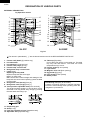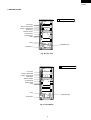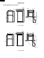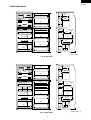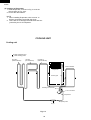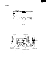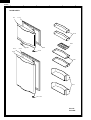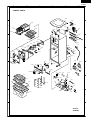
1
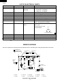
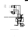
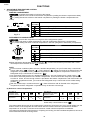
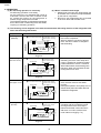
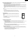
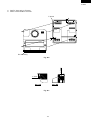
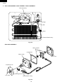
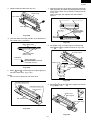
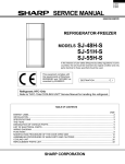
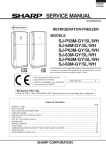
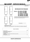
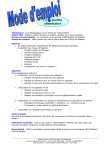
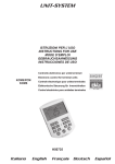
SJ-21P
SJ-D25P
SERVICE MANUAL
S9120SE25CPSF
REFRIGERATOR-FREEZER
MODELS
SJ-21P-GY
SJ-D25P-GY
SJ-21P
SJ-D25P
In the interests of user-safety (Required by safety regulations in some
countries) the set should be restored to its original condition and only
parts identical to those specified should be used.
Refrigerant; HFC-134a
Refer to "HFC-134a COOLING UNIT" Service Manual for handling this refrigerant.
DESTINATION .................. F
TABLE OF CONTENTS
page
CAUTIONS AND INFORMATIONS ................................................................................................................... 2
SPECIFICATIONS ............................................................................................................................................. 3
DESIGNATION OF VARIOUS PARTS .............................................................................................................. 4
DIMENSIONS .................................................................................................................................................... 6
LIST OF ELECTRICAL PARTS ......................................................................................................................... 8
WIRING DIAGRAM ............................................................................................................................................ 8
FUNCTIONS .................................................................................................................................................... 10
ASSEMBLING PROCEDURES OF MAIN PARTS AND CAUTIONS .............................................................. 14
COOLING UNIT ............................................................................................................................................... 22
REPLACEMENT PARTS LIST ........................................................................................................................ 24
SHARP CORPORATION
1
SJ-21P
SJ-D25P
CAUTIONS AND INFORMATIONS
In case of following troubles, the cause is not related with the failure of refrigerator.
Please mention the correct way to the customer for the use of refrigerator when the repairing.
1. Some foods freezed in the refrigerator compartment.
Do not place food directly in front of
cold air outlet.
This may lead to the food freezing.
cold air flow
IN
OUT
2. Some plastic parts were cracked or splitted.
Some household cleaning chemicals may affect the internal
food liner and plastic parts resulting in splitting or cracks
occurring.
When cleaning all plastic parts inside this refrigerator, only
use diluted dishwashing liquid(soapy water). Make sure that
all plastic parts are thoroughly rinsed with water after cleaning.
3. Water leaked on the floor.
Protrusions
Holes
Make sure the back end of Evaporating pan
rests securely on the rail.
Rail
Set Evaporating pan so that the two protrusions
on the machine come through its corresponding holes,
and move the pan to right.
Protrusions
Evaporating pan
Holes
2
Evaporating pan
SJ-21P
SJ-D25P
SPECIFICATIONS
Items
Type
Outer dimensions
(Including spacer)
Rated storage volume
Rated gross volume
Defrosting
Height
Width
Depth
System
Start
Finish
Temperature control
No-frost freezer
Deodorizing system
Interior lamp
Evaporating pan
Refrigerator
R tray S
Compartment
R tray L
Free set shelf
V tray
Vegetable case
Egg tray
Bottle pocket
R door pocket
Freezer
F-partition tray
Compartment
F tray
F door pocket
Ice cube maker
COLOR
Items
Outside color
Inside color
RATING
Models
Rated voltage
Rated frequency
Climate class
Rated input
Rated input of heating elements
Defrosting input
Refrigerant (Charging quantity)
Net weight
PLUG TYPE
Plug cord
Plug type
Destination mark
SJ-21P
2-Door
1350mm
545mm
585mm
190 liter F: 60 liter R: 130 liter
210 liter F: 73 liter R: 137 liter
Heater system
Automatic
Automatic
Automatic (Adjustable)
Yes
No
1
1
1
1
1
1
1
2
1
1
1
2
Twin ice cube maker
SJ-D25P
1510mm
545mm
585mm
225 liter F: 60 liter R: 165 liter
245 liter F: 73 liter R: 172 liter
Yes
1
2
SJ-21P-GY,SJ-D25P-GY
Gray
White
SJ-21P
(V~) 110
(Hz) 60
ST
(W) 100
(W) 158
(W) 158
HFC-134a(85g)
(kg) 43
SJ-D25P
46
2 pin
A-1
F
3
SJ-21P
SJ-D25P
DESIGNATION OF VARIOUS PARTS
EXTERNAL DESCRIPTION
By Operation manual
1
15
2
3
4
5
16
17
16
6
7
8
10
11
12
13
18
19
20
21
1
15
2
3
4
5
16
6
7
8
9
10
11
18
12
13
21
17
16
19
20
14
14
SJ-21P
SJ-D25P
Fig. D-1
The names in parenthesis" [ ]" are the denominations used in the REPLACEMENT PARTS LIST.
1.
2.
3.
4.
5.
6.
7.
Freezer shelf (Small) [F-partition tray]
Ice cube maker
Ice cube box [Ice storage box]
Freezer shelf (Large) [F tray]
Freezer temp. control knob
Refrigerator temp. control knob
Light [Lamp]
Replacing the lamp bulb
Replace lamp bulb with same type.
Base E12, MAX 10W
Make sure that the rated voltage and wattage of the
lamp bulb are correct when replacing (check the label
near the bulb).
8. Refrigerator shelf (Small) [R tray S]
9. Refrigerator shelf (Large) [R tray L]
10. Three position adjustable shelf [Free set shelf]
This shelf has three positions, it can be partly or fully
extended or be fully folded away simply by pushing
the shelf back then lifting it up.
11.
12.
13.
14.
15. Table top [Top table]
Do not place hot objects on the table top. The table
top may melt and deform. The table can resist
temperatures up to 100˚C.
16. Freezer pocket [F door pocket]
17. Light switch
18. Magnetic door seal [Door packing]
19. Egg holder [Egg tray]
20. Free pocket [R door pocket]
21. Bottle pocket
Deodorizing unit (Only for SJ-D25P)
A built-in unit which requires no manual operation
because it automatically starts operating when the
refrigerator is powered on.
Evaporating pan
Shelf [V tray]
Fruit and vegetable crisper [Vegetable case]
Adjustable foot [Adjustable leg]
4
SJ-21P
SJ-D25P
CONSTRUCTIONS
Mark: Cold air flow
Fan motor
Defrost thermostat
F-temp. control knob
Evaporator
Defrost heater
R thermostat
Defrost timer
Lamp
V tray
Vegetable case
Compressor
Fig. D-2 (SJ-21P)
Mark: Cold air flow
Fan motor
Defrost thermostat
F-temp. control knob
Evaporator
Defrost heater
R thermostat
Defrost timer
Lamp
V tray
Vegetable case
Compressor
Fig. D-3 (SJ-D25P)
5
SJ-21P
SJ-D25P
DIMENSIONS
OUTER DIMENSIONS AND CLEARANCE
more than
60
545
more than
60
585
more than
545
60
33
799.5
1073
1350
481
90
more than
420
( Unit : mm )
Fig. E-1(SJ-21P)
more than
60
545
more than
more than
more than
545
60
33
959.5
1073
1510
481
90
60
585
420
( Unit : mm )
Fig. E-2(SJ-D25P)
6
SJ-21P
SJ-D25P
379
76
182
189
70
207
110
INNER DIMENSIONS
390
379
407
207
76
141
108
384
124
291
134
414
198
152
391
384
237
84
220
220
402
129
389
(Unit : mm)
379
76
182
189
407
108
391
407
108
391
384
124
198
267
291
134
414
141
76
134
379
158
390
207
70
207
110
Fig. E-3(SJ-21P)
384
84
237
220
220
402
129
389
Fig. E-4(SJ-D25P)
7
(Unit : mm) SJ-21P
SJ-D25P
LIST OF ELECTRICAL PARTS
ITEMS
Defrost thermostat
Timer
TYPE NAME
S101
TMDFX04FB2
RATING
125V,15A
100-127V
50/ 60Hz
Thermo. fuse (defrost)
Door switch
Fan motor
Lamp
Lamp socket
R-thermostat
Defrost heater
SF70E
100424NC
3R00057B
—
—
MM1-8071F
—
250V,10A
250V,0.25A
110V,60Hz
110V,10W
250V,1A
—
100-110V
Compressor
EMI50HNP
115V
60Hz
SPECIFICATIONS
Open : 10˚C , Close : 1˚C
Integration type
Cycle time : 10h (60Hz)
Delay time : 4m (60Hz)
Cut off temperature : 70˚C
2 terminals type push-button
—
E-12
E-12 (Hard plastic body type)
ON : 3.5˚C , OFF : 0.5˚C
78.8Ω without deodorizer (SJ-21P)
78.8Ω with deodorizer (SJ-D25P)
Main : 3.85Ω
Aux : 7.70Ω
Cooling capacity 151W
Common
Terminal shape
Aux. coil
Starting relay
Protector
Compensating thermostat
Compartment heater
The black dot (
P600E
4TM319RFBYY
S101
—
—
—
125V,15A
110V, 4.8W
Main coil
—
—
Open : 25˚C , Close : 17˚C
2500Ω
) indicates non-replacement parts or part which is not replaceable itself.
WIRING DIAGRAM
Be sure to replace the electrical parts with specified ones for maintaining the safety and performance of the set.
CONNECTOR
Compensating
(O)
Thermo.
CONNECTED IN
TERMINAL BOX
Compartment
Heater
(G)
(Br)
R-Thermo.
(Br)
Fan Motor
2PIN AC
Plug /
Cord
Lamp L
FM
(R)
3
Thermo. 2
Fuse
(W)
(Bk)
(O)
(S-B)
4
Defrost
1 Timer
TM
Defrost
Heater
(Y)
(Y)
Door
Switch
(B)
Protector
(Overload relay)
Defrost
Thermo.
(Bk)
C
M
(B)
Starting relay
(P.T.C relay)
A
Compressor
B : BLUE
Bk : BLACK
Br : BROWN
O: ORANGE
R: RED
G : GRAY
P : PINK
S-B : SKY-BLUE
W: WHITE
Y: YELLOW
Figure W-1. Wiring Diagram
8
1
SJ-21P
SJ-D25P
G
Br
O
R
P
B
Bk
S-B
W
Y
: GRAY
: BROWN
: ORANGE
: RED
: PINK
: BLUE
: BLACK
: SKY-BLUE
: WHITE
: YELLOW
FAN MOTOR
DEFROST
THERMOSTAT
1
2
3
4
5
6
1
2
3
4
5
6
DEFROST
HEATER
1
2
1
2
THERMO.
FUSE
3
4
FM
DEFROST
TIMER
3
2
4
1
TM
R-THERMOSTAT
LAMP
L
(R-1)
(B-1)
(B-3)
(Y-1)
(Y-2)
(W-1)
(W-1)
3
4 (BK-1)
1
2
DOOR SWITCH
(G-1)
1
2
3
4
5
1
2
3
4
5
6
6
7
8
7
8
(B-2)
(SB-1)
(BK-1)
(G-2)
(Y-1)
(Y-2)
(BR-1)
(SB-1)
(BR-2)
COMPARTMENT HEATER
(Br)
(B)
(G)
(O)
COMPENSATING
THERMO.
PROTECTOR
1
COMPRESSOR
L
E
C
M
A
N
STARTING
RELAY
Fig. W-2. Electric Accessories Layout
9
SJ-21P
SJ-D25P
FUNCTIONS
1. ADJUSTABLE TEMPERATURE CONTROL
(1) Temperature control
FREEZER COMPARTMENT
regulates the quantity of cold air to the freezer.
" "(7) setting directs more cold air to the freezer compartment. (making the freezer compartment colder)
" "(1) setting directs less cold air to the freezer compartment. (making the freezer compartment less
colder)
KNOB
SETTING
1
2
3
4
5
6
PURPOSE
For making ice rapidly of fast freezing. And winter season.
When restocking with fresh food.
For normal freezing.
For storing frozen food for a short period (up to one month).
When frozen food or ice cream is not stored.
7
Fig. F-1.
REFRIGERATOR COMPARTMENT
controls the compressor running time of the refrigeration system.
" "(5) setting will result in colder temperature in the both (refrigerator and freezer) compartments.
" "(1) control setting will result in warmer temperature in the both (refrigerator and freezer) compartment.
2
3
KNOB
SETTING
4
5
PURPOSE
For keeping freshness of food longer.
When the refrigerator does not provide sufficient cooling.
For normal operation.
When the refrigerator provides excessive cooling.
Fig.F-2.
When refrigerator temperature control sets to the "
case adjust control set back to the "
" position.
", some foods stored may become frozen. In this
NOTE:
For hot summer conditions (about over 35˚C ambient temperature), set your Freezer temp. control knob
to less colder than "
" (towards " "). This is because " " setting may result in too little air flow to the
refrigerator compartment, causing too warm temperature in the refrigerator compartment. And set your
Refrigerator temp. control knob to colder than "
".
In a cold kitchen (about under 10˚C ambient temperature), set your Freezer temp. control knob to " "
to avoid too warm temperature in the freezer compartment. This is because the compressor operation is
too short in winter, and not enough cold air is provided to the freezer compartment. And if the foods in the
refrigerator compartment freeze, you must set the Refrigerator temp. control knob to less colder setting.
(toward " ").
With the Freezer temp. control knob set to " ", there will be less cold air directed to the refrigerator
compartment, and the refrigerator compartment may not become cold enough.
(2) Reference value of temperature
SETTING OF
FREEZER TEMP.
CONTROL KNOB
Freezer
temperature
SETTING OF
REFRIGERATOR TEMP.
CONTROL KNOB
Approx.
-21 °C
Approx.
-18 °C
Approx.
-15 °C
Refrigerator
temperature
Approx.
0 °C
Approx.
3 °C
Approx.
6 °C
The values shown above refer to the case where the
freezer temp. control knob is set at "
".
The values tables above refer to the measurement carried out center area and 1/3 of overall height from the
bottom at each of the refrigerator and the freezer after the machine has been operated at an ambient
temperature of 32˚C with no food stored and the door closed until the temperature is stabilized.
The values vary depending upon frequency of opening and closing, the doors ambient temperature, amount of
stored foods and manner of storing foods.
10
SJ-21P
SJ-D25P
(3) Temp. control system
Freezer Temp. Control Knob
The Freezer temp. control knob regulates the quantity of cold air to the freezer.
"
" (7) setting directs more cold air to the freezer compartment.
(making the freezer compartment colder)
"
" (1) setting directs less cold air to the freezer compartment.
(making the freezer compartment less colder)
Fan
Cold air
1
2
3
4
5
6
7
1
3
4
5
6
7
regulating the quantity
of cold air.
regulating the quantity
of cold air.
FREEZER
COMPARTMENT
2
Evaporator
much cold air
less cold air
FREEZER
COMPARTMENT
REFRIGERATOR
COMPARTMENT
REFRIGERATOR
COMPARTMENT
much cold air
less cold air
Refrigerator Temp. Control Knob
Compressor
The Refrigerator temp. control knob controls the
compressor & the fan running time of the refrigerator system.
"
" setting will result in colder temperature in the both
(refrigerator and freezer) compartments.
"
" control setting will result in warmer temperature in the
both (refrigerator and freezer) compartments.
2
1
3
4
2
3
4
1
5
high cold power
5
low cold power
FREEZER
COMPARTMENT
REFRIGERATOR
COMPARTMENT
controlling the compressor
& the fan running time
controlling the compressor
& the fan running time
Normal operation (ex. at 20 °C ambient temperature)
Temp.(°C )
30
OFF ON OFF ON
Compressor & Fan
20
Ambient temperature
10
0
Refrigerator compartment temperature (at "
"position)
-10
-20
Time
Freezer compartment temperature (at "
11
"position)
SJ-21P
SJ-D25P
2. DEFROSTING
(1) No defrosting operation is necessary.
No defrosting operation is necessary.
As this machine is so designed that a built-in
evaporator cools air and a fan circulates cooled
air, neither the freezer nor the refrigerator is
frosted, though Evaporator is frosted.
The frosted Evaporator is defrosted automatically
due to the function of defrosting timer and heater,
requiring no defrosting operation.
(2) Where is melted frost brought.
1. Melted frost is brought into Evaporating pan
at the back of the set and is evaporated here
by the heat of compressor.
2. Be sure to use Evaporating pan as inserted
so as to be level with the outer case.
(3) The following circuit diagrams in the table show automatic defrosting function of the refrigerator with
timer and defrosting thermostat.
Electric diagram
Defrost thermostat ON
Timer contact
Thermo. fuse
Defrost heater
TM
Defrost
thermostat (ON)
COMP
Compressor
SOURCE
Thermostat
Compressor running
Timer motor running
Timer motor
Operation
1. Cooling
(Normal)
Description
The integration timer integrates running
time of the compressor.
When it reaches cycle time of defrost
timer, the timer contact is changed to
start defrosting.
Fig. F-3
Defrost thermostat ON
Compressor stops
Timer motor stops
(Time 20 to 30 min.)
Timer contact
Thermo. fuse
Defrost heater
TM
Defrost
thermostat (ON)
COMP
Compressor
SOURCE
Thermostat
Timer motor
2. Defrosting
The timer contact is changed to start
defrosting, the timer motor stops and
power is supplied to the defrost heater.
It takes about 20 to 30 min. to defrost.
When little frosted, the defrosting take
little time. When much frosted, the defrosting takes much time.
Fig. F-4
Defrost thermostat OFF
SOURCE
Thermostat
Compressor stops
Timer motor running
Timer contact
Thermo. fuse
Defrost heater
TM
Defrost
thermostat (OFF)
COMP
Compressor
(Time approx. 5 min.)
Timer motor
3. Drain
When the defrost thermostat becomes
OFF, the timer motor at rest starts
running.
During the operation time (delay time of
defrost timer) defrosted water drained
outside the refrigerator.
Fig. F-5
Defrost thermostat OFF
Compressor running
Timer motor stops
(Re-start)
Timer contact
Thermo. fuse
Defrost heater
Defrost
thermostat (OFF)
TM
Fig. F-6
12
COMP
Compressor
SOURCE
Thermostat
Timer motor
4. Cooling
Timer contact is changed to cooling
operation and the compressor starts
running and the timer motor stops.
Defrost thermostat contact becomes
ON when it’s cooled. And the timer
motor starts running(Fig. F-3)
SJ-21P
SJ-D25P
(4) As a reference to determine the causes of trouble, malfunction and phenomena are described below.
Refer to the following when repairing.
1. Disconnection of Defrost heater
As off-cycle defrosting is performed, the defrosting time is extremely prolonged.
Each time defrosting is started, the freezer temperature rises and a portion of ice and stored foods are melted.
2. Melted Thermo. fuse or opened-circuit due to the defect of Defrost thermostat.
When the above mentioned trouble occurs in cooling operation, the timer motor does not run, defrosting will
not take place, and consequently freezing is caused.
In the above mentioned condition, when the timer shaft is turned by hand to defrost, the timer motor runs
during the operation time. However, the motor stops from the time when the contact is changed, and freezing
causes.
NOTE:
As Thermo. fuse assembly is intended to prevent dangers, do not use it under shorted condition even for a
short period.
3. When Defrost thermostat failure causes the circuit to remain closed.
The thermostat assembly connected with Thermo. fuse in the same way.
A portion of ice or stored foods are melted when Thermo. fuse is worked.
3. DEW PREVENTION
The hot pipe, namely D.P.-condenser, is arranged around the flange part of
cabinet and the C-partition plate, preventing dew from being generated on the
cabinet.
NOTE:
D.P.-condenser pipe may be felt hot if touched by hand while the compressor
is in operation.
If you are asked about this, please explain that the hot pipe serves to
prevent the dew generation.
Hot pipe
Fig. F-7
4. INSPECTION OF INITIAL STARTING
(1) Inspection of cooling unit
1. Set the temperature control knob to "MAX" and check that the compressor starts to operate.
2. Depress the door switch to run the fan and check that cool air is blown out of the cold air outer of the
freezer and the refrigerator.
3. When the compressor does not work, check that the timer is not set to "defrost" position.
4. It takes about an hour and a half or 2 hours to put food in the refrigerator after starting operation.
NOTE:
After return the temperature control knob to "MED" position.
When the refrigerator is operated initially after installed,the compressor may vibrate excessively for 1 to 2
min. However, vibration becomes normal if it is continuously operated.
(2) Inspection of defrost device
Operate the refrigerator for 20 to 30 min. and then check the defrost device in the following procedures :
Allow 5 min. to restart the compressor since immediate starting after stopping will cause unsmooth operation.
1. Turn the timer shaft clockwise with a screw driver.
At this time, make certains the timer clinks and the compressor stops.
2. After more than 5 min., turn the shaft further to operate.
Make certain cooling operation is started again.
13
SJ-21P
SJ-D25P
ASSEMBLING PROCEDURES OF MAIN PARTS AND CAUTIONS
CAUTION: DISCONNECT THE UNIT FROM THE POWER SUPPLY BEFORE ANY REPAIRING.
1. F-LOUVER ASSEMBLY
Aluminum tape
(65mm x 290mm, 65mm x 125mm)
A-sealer EVC B
F-louver sealer
F-louver
E.V. duct AL
E.V. duct insulation
A-sealer EVC A
F control label
A
C
A
F temp. control knob
Fig. A-1
1. Stick E.V. duct AL to E.V. duct insulation.
3. Stick F control label to F-louver.
F-control label
E.V. duct AL
Sec. AA
F-louver
Fig. A-4
Fig. A-2
2. Stick A-sealer EVC A & A-sealer EVC B to E.V. duct
insulation.
(Note) Do not fix F-control label upside down.
4. Insert F-temp. control knob to F-louver.
A-sealer EVC A
E.V. duct AL
3 ~ 5 mm (102 mm)
F-temp. control knob
a
b
D
B
D
b
3 ~ 5 mm
B
a
F-louver
a
View from C
F-louver
Fig. A-3
b
Sec. DD
F-temp. control knob
Fig. A-5
14
Sec. BB
SJ-21P
SJ-D25P
5. Set E.V. duct ass'y to F-louver.
6. Stick F-louver sealer to F-louver.
F-louver
B
B
A
A
E.V duct ass’y
1~ 3mm
Fig. A-6
1~ 3mm
Sec. AA
Sec. BB
Fig. A-7
15
SJ-21P
SJ-D25P
2. FM COVER ASSEMBLY AND THERMAL FUSE D ASSEMBLY
FM cover ass'y
Tape
Clip
Tape
Thermal fuse D ass'y
Fig. A-8
FM COVER ASSEMBLY
Motor cushion
Fan motor
A-sealer FM
Motor holder
Motor cover
Propeller fan 90
Fastening band A
Fan clamp
Defrost thermo. ass’y
Fig. A-9
16
SJ-21P
SJ-D25P
1. Stick A-sealer FM to Motor holder.
Motor
holder
A
finish
start
A-sealer
FM
Fan motor
Motor cushion
Motor holder
0 ~ 1mm
A
A-sealer FM
Motor cover
Sec. AA
Fig. A-10
A-sealer FM
Motor cushion
Sec. Horizontal Center
A-sealer FM
Motor cover
2. Insert the fasten terminal of Defrost thermo. ass'y
into the terminal of Fan motor. (2 pcs.)
Defrost thermo. ass'y has positive lock. (No. pole, so
changeable)
Check locking by pulling them with more than
10N(1kgf), all wires after assemble them.
NOTE
(1) Assemble so that terminal of Fan motor does not
deform.
(2) Take care not to stress to terminal of Fan motor after
wiring.
Motor holder
Motor cushion
Fan motor
Motor cushion
A-sealer FM
Sec. Length Center
Fig. A-13
Defrost thermo. ass'y
6. Set Defrost thermo. ass'y to " 5 " ass'y as shown in
Fig. A-14.
" 5 " ass’y
Defrost thermo.
ass’y
terminal
fasten terminal
Fan motor
Fig. A-11
C
D
3. Set Motor cushion and " 2 " ass'y to " 1 " ass'y.
C
D
Thermostat sensing face (aluminum side)
should be fixed horizontally, lower side.
" 2 "ass’y
" 1 "ass’y
wire
Insert
Insert
View from B
B
wires
wires
Fastening band A
Fig. A-12
before
4. Insert the wire of Defrost thermo. ass'y to the place
of " 3 " ass'y as shown in Fig. A-12.
5. Set Motor cushion and Motor cover to " 4 " ass'y as
shown Fig. A-13.
after
Sec. CC
Fig. A-14
17
before
after
Sec. DD
SJ-21P
SJ-D25P
7. Set Propeller fan 90 and Fan clamp to " 6 " ass'y as shown in Fig. A-15.
Fan clamp
slit
Fan clamp
shaft
Propeller fan 90
7.5 + 0.5
slit
Propeller fan 90
" 6 " ass’y
Fan clamp
fan boss
GOOD
NO GOOD
Fig. A-15
NOTE
(1) Slit of each Fan clamp and Propeller fan 90 should not be at same position.
(2) Fan clamp should be inserted virtically to the end of boss.
(3) Propeller fan 90 should not be taken out from shaft when pulled by 2kgf.
THERMAL FUSE D ASSEMBLY
1. Set Fuse ass'y to Thermo. fuse holder.
2. Wind the aluminum tape to the Thermo. fuse holder.
Fuse ass'y
aluminum tape
(size 40 x 130)
Thermo. fuse holder
View from D
aluminum tape
wire
Fuse ass'y
tube
D
A
Datum : R end
wire
wire
A
B
Sec. AA Sec. BB
C
B
Sec. CC
aluminum tape
C
Thermo. fuse holder
after assembled
Fig. A-16
18
SJ-21P
SJ-D25P
3. R-CBOX ASSEMBLY
Lamp socket
R-air guider ass’y
Lamp
Defrost timer
R-thermostat
Insulating tube
Warning label
F-temp. control knob
R-Cbox cover
D timer lead ass’y
Fig. A-17
5. Fix R thermostat with screw and make up the
tube of R thermostat as shown Fig. A-20.
1. Connect D timer lead ass'y to Defrost timer,
R thermostat.
2. Screw Lamp to Lamp socket. (Fig. A-18)
D timer lead ass’y
4
3
2
1
Screw
Defrost timer
R thermostat
Paper taping
40 X 80
Lamp
Insulating tube
R thermostat
Lamp socket
Fig. A-18
100 + 5mm
3. Fix Lamp socket with screw, and Defrost timer
with screw.
4. Cover the capillary tube of R thermostat by
Insulating tube and bend them as shown in
FigA-19.
Fig. A-20
6. Insert F-temp. control knob to R thermostat.
7. Stick warning label on R-cbox cover as shown
Fig. A-21.
25mm
Insulating tube
R-Cbox cover
+2mm
70_
R thermostat
80mm
50±2
9±2
15_
+2mm
A
15_
+2mm
+2mm
25_
+ 2mm
55_
+5
5 -0mm
55mm
185mm
View From A
Warning label
Fig. A-19
NOTE
Fig. A-21
Minimum bending radius is R5.
There should be no gas leakage by reforming
of Capillary tube.
8. Set R-air guider ass'y on R-cbox cover.
19
SJ-21P
SJ-D25P
4. DEFROST HEATER
(2) Replacement of Def. heater ass'y.
(1) Taking-out Evaporator
1. Disconnect the lead wires inserted in the rib of center
partition (Fig. A-25 : 8 pcs.).
1. Take out F-louver ass'y (Fig. A-22).
Evaporator
Food liner convex part
Tape
Fig. A-22
2. As shown in Fig. A-23, pull the upper part of Evaporator
toward you, pull it diagonally so that the pipe of
Evaporator does not contact the convex part of food
liner.
Tape
Vinyl tape
Food liner convex part
Def. heater L ass'y
Evaporator
Fig. A-25
Pipe
2. Raise the protrusion part of Drain support AL
(Fig. A-26). Then remove Heater cover.
Protrusion part of Drain support (2 pcs.)
Fig. A-23
3. As shown in Fig. A-24, bend the removed Evaporator
horizontally so that Defrost heater can be replaced
easily.
NOTE: When pulling Evaporator and bending the
pipes, pay attention so as not to break and
deform the pipes. Still, take care not to hurt
yourself by fin of Evaporator.
Def. heater ass’y
Heater cover
Removing direction
Mounting direction
Fig. A-26
3. Open Def. heater fixed part of Drain support
(Fig. A-27) to the right and left, then remove
Def. heater ass'y.
Removing direction
Mounting direction
Evaporator
Fig. A-24
Screw
Screw
Drain support
Def. heater ass’y
Fig. A-27
20
SJ-21P
SJ-D25P
4. Replace Defrost heater with new one.
7. Stick the longer wire to the Drain support by aluminum
tape (2 pieces), and wind vinyl tape (2 pieces) to lead
wires of Def. heater ass'y by aluminum tape as shown
in Fig. A-31.
Glass cloth tape part shall be both side of Drain
support.
Heater cover
Def. heater ass’y
a
g
c
Glass cloth tape
Glass cloth tape
e
d
Drain support
b
f
h
aluminum tape
(W40 x L60)
Vinyl tape
Fig. A-28
5. Wind the Glass cloth tape (3M: No. 27) to lead wire of
Def. heater ass'y. (2 places)
Fig. A-31
Def. heater ass’y
340
8. Set Heater cover on Drain support, and bend top
edge c and d to outside as shown in Fig. A-32.
40
40 30
Heater cover
c
Drain support
Glass cloth tape
(W40 x L25)
Lead wire
d
Glass cloth tape
Wind the Glass cloth tape
more than 2 turns.
Heater cover
top edge
A
Drain support
Fig. A-29
A
Def. heater ass’y
6. Band a and b of Drain support to right angle (90˚)
set Def. heater ass'y. (Fig. A-30)
NOTE
Don't touch on glass tube with bare hand.
Sec. AA
Fig. A-32
this side is longer wire
a
this side is shorter wire
9. Bend e , f , g and h Drain support 2 as shown
in Fig. A-33.
Drain support
18.5
Heater cover
5
~7
60
Drain support
b
Def. heater ass’y
Sec. BB
g
Def. heater ass’y
e
f
Fig. A-30
B
B
Fig. A-33
21
h
SJ-21P
SJ-D25P
(3) Installing of Evaporator
1. Install Evaporator as shown in Fig. A-22 in the
reverse order of Fig. A-23.
2. Correct the deformed fin.
NOTE
1. When installing Evaporator, take care not to
deform significantly and break the pipes.
2. Take care not to damage the lead wires and hurt
yourself by the fin of Evaporator.
COOLING UNIT
Cooling unit
Mark: Refrigerant flow
Mark: Brazing portion
Hot pipe L
(Side condenser)
Hot pipe
(DP-condenser)
Hot pipe R
(Side condenser)
Back condenser
Evaporator
Suction pipe
Discharge P connector
S.P connector
Compressor
Capillary tube
Dryer
Fig. C-1
22
SJ-21P
SJ-D25P
Location
Dryer
Capillary tube
Charge pipe
Hot pipe
Evaporator
Charge pipe E
Suction pipe
Back condenser
S.P
Discharge
connector
P connector
Compressor
Fig. C-2
Back condenser
to Hot pipe
S.P connector
to Suction pipe
Pinch Point
Hot pipe
to Dryer
Charge pipe
to Dryer
S.P connector
to Compressor’s
suction tube
Discharge P. connector
to Back condenser
Charge pipe E
to Compressor’s
process tube
Compressor’s discharge pipe
to Discharge P. connector
Fig. C-3
23
Dryer
to Capillary tube
SJ-21P
SJ-D25P
REPLACEMENT PARTS LIST ( SJ-21P/D25P)
REF. NO.
PART NO.
DESCRIPTION
Q'TY
CODE
SJ-21P
-GY
SJ-D25P
-GY
1
1
1
1
1
1
1
1
1
1
1
1
1
1
1
1
1
1
1
1
1
1
1
1
1
1
1
1
AP
AN
AW
BA
AY
AQ
AE
AK
AX
BG
AZ
AY
AH
AU
AN
1
1
1
1
1
1
1
2
1
1
1
1
1
1
1
1
1
1
1
1
1
1
2
1
1
1
1
1
1
1
2
1
1
1
8
2
1
1
1
1
1
1
1
1
1
1
1
1
2
1
1
1
1
1
1
1
1
1
1
1
1
1
1
2
1
1
1
1
1
1
1
2
1
1
1
8
2
1
1
1
1
1
AL
AN
AE
AF
AH
AF
AF
AP
AC
AD
AD
AK
AE
AP
AF
AP
AB
AC
AH
AF
AD
AB
AF
AD
AH
AH
AE
AM
AK
AG
AF
AE
AC
AD
AP
AE
AD
AB
AM
AD
AY
AG
AF
AE
1
2
2
1
1
1
1
1
2
2
1
1
1
1
BR
AH
AF
AU
BS
BQ
AW
AV
AQ
ELECTRIC PARTS
1-2
1-5
1-6
1-7
1-8
1-9
1-11
1-12
1-13
1-15
1-15
1-16
1-22
1-23
1-27
FFS-TA044CBK0
QACC-A133CBE0
QSWTDA025CBE0
RMOTRA044CBE0
RTHM-A085CBE0
FTHM-A034CBKZ
RLMP-A002CBE0
QSW-PA076CBEA
RSTT-A135CBE0
FHETBA129CBE0
FHETBA130CBE0
RHOG-A122CBE0
FCNW-A569CBK0
FW-VZA129CBE0
FTHM-A036CBKZ
Fuse ass'y
Source cord
Defrost timer
Fan motor
R thermostat
Defrost thermo.ass'y
Lamp
Door switch
Starting relay
Def.heater ass'y
Def.heater ass'y
Protector
Relay wire ass'y
D timer lead ass'y
C. thermo. ass'y
2-2
2-3
2-4
2-6
2-9
2-10
2-12
2-13
2-15
2-16
2-18
2-20
2-21
2-22
2-23
2-24
2-25
2-26
2-28
2-29
2-30
2-31
2-32
2-33
2-34
2-35
2-37
2-38
2-39
2-39
2-40
2-40
2-41
2-41
2-42
2-43
2-44
2-45
2-46
2-47
2-50
2-52
2-53
2-55
LFRM-A145CBFB
DHNG-A304CBK0
LHLD-A438CBF0
FAJS-A006CBFA
DHNG-A396CBMZ
DHNG-A301CBM0
FGID-A063CBY0
LBND-A018CBE0
JKNB-A043CBFB
JKNB-A036CBFB
LPLTMA399CBP0
PCOV-A205CBFA
LHLD-A440CBF0
LPLTMA490CBP0
PSHEMA154CBP0
PSHEMA160CBE0
PSEL-B464CBE0
PSEL-B465CBE0
PDUC-A066CBF0
LHLD-A473CBE0
LCRA-A010CBE0
PSEL-B472CBE0
LHLD-A389CBF0
NFANPA012CBF0
LHLD-A444CBF0
LHLD-A445CBF0
PTUBBA065CBE0
GCOVPA093CBRB
HGRL-A161CBFB
HGRL-A162CBFB
PFPFPB053CBF0
PFPFPB060CBF0
PSEL-B469CBE0
PSEL-B483CBE0
HGRL-A163CBFB
PSEL-B468CBE0
TLAB-A721CBR0
LHLD-A124CBFE
LPLTMA553CBP0
PTUBBA067CBE0
GTOP-A023CBFA
PBOX-A083CBFA
PCOVPA183CBFA
LHLD-A359CBFA
Ice maker
Bottom hinge s-ass'y
E.v.holder
Adjustable leg ass'y
Center hinge r ass'y
Upper hinge ass'y
R-air guider ass'y
Fastening band a
F-temp. control knob
F-temp. control knob
Dryer support
Lamp cover
Term.fuse holder
Drain support
Heater cover
E.v.duct al
A-sealer evc a
A-sealer evc b
E.v.duct insulation
Clip
Fan clamp
A-sealer fm
Motor cushion
Propeller fan 90
Motor holder
Motor cover
Insulating tube
R-cbox cover
Multi louver
Multi louver
R-louver insu.
R-louver insu.
A-sealer ml
A-sealer ml
F-louver
F-louver sealer
F control label
K-frame holder
Ev.pan support
Insulating tube
Top table
Terminal box
Terminal cover
T-box holder
3-1
3-1-1
3-1-2
3-2
3-12
3-12
3-13
3-13
3-25
FDORFB444CBKZ
NBRGPA013CBFB
LSTPPA097CBFA
FPACGA256CBK0
FDORRB272CBKZ
FDORRB277CBKZ
FPACGA257CBK0
FPACGA259CBK0
HBDGDA909CBEA
F-door ass'y
Nylon bearing 2
Door stopper
F-door packing
R-door ass'y
R-door ass'y
R-door packing
R-door packing
Door trim
MECHANICAL PARTS
DOOR PARTS
24
SJ-21P
SJ-D25P
REF. NO.
PART NO.
DESCRIPTION
Q'TY
CODE
SJ-21P
-GY
SJ-D25P
-GY
1
1
3
1
1
3
AA
AH
AH
1
1
1
1
1
1
1
1
1
1
2
1
2
1
1
1
1
1
1
1
1
1
1
1
1
2
1
2
2
AR
AS
AQ
AS
AN
AQ
AL
AQ
AS
AM
AR
AM
AG
AN
AP
1
4
1
4
1
1
4
1
1
1
1
1
1
1
4
1
4
1
1
4
1
1
1
1
1
1
BR
AF
AS
AA
AD
AG
AD
AU
AG
AG
AT
AE
AG
1
1
1
1
1
4
1
1
1
1
1
1
1
1
1
1
1
4
1
1
1
1
1
1
AV
AK
BB
BB
AG
AB
AD
AL
AL
AH
AH
AC
AE
OTHER PARTS
4-1
4-3
4-4
LX-BZ0202JBE0
QTAN-A012CBE0
QTAN-A013CBE0
Special screw
Solderless term. b
Solderless term. a
5-1
5-2
5-3
5-4
5-5
5-6
5-9
5-10
5-11
5-12
5-14
5-15
5-16
5-17
5-19
FSRA-A199CBYZ
USRA-A214CBFB
USRA-A215CBFB
USRA-A212CBFB
UTNA-A260CBFB
UTNA-A261CBFB
USRA-A227CBFB
USRA-A266CBFA
USRA-A216CBFB
UYOK-A148CBFB
UYOK-A241CBFB
UPOK-A161CBFB
UTNA-A167CBFC
UPOK-A139CBFB
UPOK-A140CBFB
Ice cube maker
R tray l
R tray s
F tray
Free set shelf b
Free set shelf f
F-partition tray
Evaporating pan
V tray
Ice storage box
Vegetable case
F door pocket
Egg tray
Bottle pocket
R door pocket
ATTACHMENT PARTS
CYCLE PARTS
6-1
6-2
6-3
6-4
6-5
6-6
6-8
6-9
6-10
6-11
6-18
6-21
6-23
PCMPLA164CBE0
PSPAGA041CBE0
LFRMMA013CBP0
LX-WZA003CBE0
PPIPCA252CBE0
PPIPCA309CBE0
PSPAFA033CBE0
FDRY-A008CBK0
PKYU-A034CBE0
PKYU-A035CBE0
PCOVPA209CBE0
PPIPCA322CBE0
PPIPCA315CBE0
Compressor
Rubber grommet
Base frame
Washer
Charge pipe
S.p connector
Sleeve
Dryer
Sp-butyl f
Sp-butyl h
Terminal cover
Charge pipe e
Discharge p.conecter
MISCELLANEOUS
90-1
90-2
90-3
90-3
90-4
90-5
90-7
90-8
90-9
90-10
90-11
90-13
90-21
CPADBA663YDK0
CPADBA661YDK0
SPAKCJ097YDEZ
SPAKCJ105YDEZ
TINS-A521CBRZ
TLAB-A473CBR0
TLAB-A614CBE0
SPADBB974YDE0
SPADBB975YDE0
SPADBB976YDE0
SPADBB977YDE0
TINS-A366CBR0
TLAB-B009CBRZ
Bottom pad ass'y
Top pad ass'y
Packing case d25p-f
Packing case 21p-f
Operation manual
Lamp label
Case label gy
Corner post r
Corner post l
Corner post bl
Corner post br
Srv.station list
Caution label rof
HOW TO ORDER REPLACEMENT PARTS
To have your order filled promptly and correctly, please furnish the following information.
1. MODEL NUMBER
3. PART NO.
2. REF. NO.
4. DESCRIPTION
25
SJ-21P
SJ-D25P
1
2
3
4
5
6
DOOR PARTS
A
A
3-1
3-1-1
B
B
5-15
C
C
5-16
3-1-1
3-2
3-25
3-13
3-1-2
3-12
D
D
5-19
E
E
F
F
5-17
G
G
3-1-2
SJ-21P
SJ-D25P
H
1
2
3
4
26
5
6
H
SJ-21P
SJ-D25P
1
2
3
4
5
6
CABINET PARTS
A
A
2-50
6-11
2-2
6-10
B
B
2-47
2-10
5-1
5-9
2-4
2-45
2-21
5-12
1-2
2-23
2-35
5-4
C
1-15
2-32
2-31
2-43
2-22
2-32
2-33
2-30
1-5
2-45
1-7
2-29
1-9
2-26
C
2-45
2-9
2-28
2-34
2-42
2-13
D
1-12
2-24
D
2-46
5-10
2-25
2-55
2-12
2-44 2-15
2-38
2-6
1-23
1-6
4-3
2-3
1-11
E
2-53
1-8
4-4
2-13
2-37
E
2-52
2-20
6-5
6-6
6-23
2-16
5-3
6-9
1-27
2-18
5-2
F
5-6
6-21 6-1
6-4
6-8
1-22
F
6-3
5-5
2-41
4-1
2-40
1-13
5-11
2-39
6-2
5-14
1-16
6-18
G
G
SJ-21P
SJ-D25P
H
1
2
3
4
27
5
6
H
SJ-21P
SJ-D25P
COPYRIGHT © 2001 BY SHARP CORPORATION
ALL RIGHTS RESERVED.
No part of this publication may be reproduced, stored in retrieval systems, or
transmitted in any form or by any means,
electronic, mechanical, photocopying, recording, or otherwise, without prior written
permission of the publisher.
21CPRF/ 25CPSF
28
2001 SHARP CORP. (09K0.10E) Printed in Japan