1
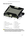
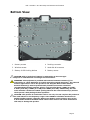
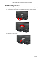
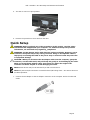
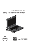
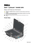
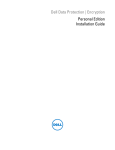
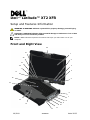
Dell™ Latitude™ XT2 XFR
Setup and Features Information
WARNING: A WARNING indicates a potential for property damage, personal injury,
or death.
CAUTION: A CAUTION indicates either potential damage to hardware or loss of data
and tells you how to avoid the problem.
NOTE: A NOTE indicates important information that helps you make better use of your
computer.
Front and Right View
22
21
1
20
2
19
3
18
4
17
16
5
15
6
7
14
8
9
13
10
11
12
08/2009
4FNPNA00
Model P05S
Dell™ Latitude™ XT2 XFR Setup and Features Information
1
Display
12
Wireless radio on/off switch
2
Ambient light sensor
13
Touch pad
3
Device status lights
14
Touch pad/Track stick buttons
4
Digital array microphone
15
Track stick
5
Biometric reader
16
Keyboard
6
Microphone connector
17
Digital array microphone
7
Headphones connector
18
Power button
8
ExpressCard slot
19
Windows security button
9
Secure digital (SD) card slot
20
Screen rotate button
10
USB/e-SATA combo connector
21
Dell Control Point (DCP) button
11
Wi-Fi Catcher™ button
22
Hot Swappable Modules: Camera or
GPS (optional)
NOTE: Press <Fn><F9> to toggle between WLAN and WWAN. Latitude XT2 XFR does not
support simultaneous operation of WLAN and WWAN modes.
Page 2
Dell™ Latitude™ XT2 XFR Setup and Features Information
Back and Left View
16
15
1
14
13
2
12
3
11
4
10
9
5
8
9
7
6
1
Speaker
Tablet grip
2
IEEE 1394 connector
10
Rotating hinge
3
USB connector (for power share)
11
Powered USB connector
4
QuadCool™ Thermal Management
12
Network connector
5
Pen tether anchor
13
Video connector
6
Pen
14
AC adapter connector
7
Pen indicator LED
15
Tablet back button
8
Power / battery charge indicators
16
Scroll control button
WARNING: Do not block, push objects into, or allow dust to accumulate in the air
vents. Do not store your Dell™ computer in a low-airflow environment, such as a
closed briefcase, while it is running. Restricting the airflow can damage the computer
or cause a fire. The computer turns on the fan when the computer gets hot. Fan noise
is normal and does not indicate a problem with the fan or the computer.
Page 3
Dell™ Latitude™ XT2 XFR Setup and Features Information
Bottom View
4
1
2
5
3
6
1
Memory access
4
Docking connector
2
Wireless access
5
Hard disk drive access
3
Battery & HDD locking latches
6
Battery access
CAUTION: Risk of explosion if battery is replaced by an incorrect type.
Dispose of used batteries according to the instructions.
WARNING: This equipment is provided with external antenna connector(s) for
connectivity to a Port Replicator for mobile external mounted antenna(s). The external
antenna approved for use in this product is the AP-Quad Mode combo antenna.
External antenna(s) must be professionally installed and cannot exceed the
recommended maximum antenna gain for each specified band: 2.4GHz (3.24 dBi),
5.2GHz (3.73 dBi), 5.5GHz (4.77 dBi) and 5.8GHz (3.87 dBi). Additionally, the user
must maintain a minimum of 20cm spacing between the external antenna(s) and the
whole person’s body during wireless operation.
CAUTION: This product is restricted to indoor use only. The FCC requires the product to
be used indoors for the frequency range 5.15-5.25GHz to minimize interference in
Mobile Satellite systems’ channels. High Power Radars are the primary users of the
5.25-5.35GHz and 5.65-5.85GHz bands. These radar stations can cause interference
with and/or damage the product.
Page 4
Dell™ Latitude™ XT2 XFR Setup and Features Information
I/O Door Operation
All ports and I/O connectors on the computer are secured behind locking I/O doors. To open the I/O
locking doors, use the following procedure.
1. The image below shows the door in its closed and locked position. Lift the door flap.
2. To unlock the door, rotate the flap clockwise 1800.
3. Pull the flap to open the door.
Page 5
Dell™ Latitude™ XT2 XFR Setup and Features Information
4. The door is now in its open position.
5. Reverse the procedure to close and lock the door.
Quick Setup
WARNING: Before you begin any of the procedures in this section, read the safety
information that shipped with your computer. For additional safety best practices
information, see www.dell.com/regulatory_compliance.
WARNING: The AC adapter works with electrical outlets worldwide. However, power
connectors and power strips vary among countries. Using an incompatible cable or
improperly connecting the cable to the power strip or electrical outlet may cause fire
or equipment damage.
CAUTION: When you disconnect the AC adapter cable from the computer, grasp the
connector, not the cable itself, and pull firmly but gently to avoid damaging the cable.
When you wrap the AC adapter cable, ensure that you follow the angle of the
connector on the AC adapter to avoid damaging the cable.
NOTE: Some devices may not be included if you did not order them.
NOTE: All ports and I/O connectors are sealed behind I/O locking doors. See section above on
I/O Door Operation.
1. Connect the AC adapter to the AC adapter connector on the computer and to the electrical
outlet.
Page 6
Dell™ Latitude™ XT2 XFR Setup and Features Information
2. Connect the network cable.
3. Connect USB devices, such as a mouse or keyboard.
4. Connect IEEE 1394 devices, such as a DVD player.
5. Open the computer display and press the power button to turn on the computer.
1
2
1
Power indicator
2
Battery charge indicator
Page 7
Dell™ Latitude™ XT2 XFR Setup and Features Information
NOTE: It is recommended that you turn on and shut down your computer at least once before
you install any cards or connect the computer to a docking device or other external device, such
as a printer.
Battery
Battery Removal
1. Ensure that the computer is turned off.
2. If the computer is connected to a docking device (docked), undock it. See the documentation
that came with your docking device for instructions.
3. Ensure that the computer is turned off.
4. Turn the computer upside down and place on a flat surface.
5. Lift the locking latches on the left and right side of the battery.
6. Push the locking latches outward, as shown below.
Page 8
Dell™ Latitude™ XT2 XFR Setup and Features Information
7. While continuing to push the locking latches, slide the battery back approximately .100”.
8. Lift and remove the battery from the computer.
Page 9
Dell™ Latitude™ XT2 XFR Setup and Features Information
Battery Replacement
1. Turn the computer upside down, and place on a flat surface.
2. Lift and place the battery into the computer.
3. Then slide the battery in the direction shown in the image below approximately .100”. The
battery will lock into place with a click and a mechanical stop.
Page 10
Dell™ Latitude™ XT2 XFR Setup and Features Information
4. Push the battery locking latches down into their flat positions.
Hard Disk Drive (HDD)
Remove a HDD
1.
2.
3.
4.
Ensure that the computer is turned off.
Turn the computer upside down, and place on a flat surface.
Remove the battery as discussed in the Battery section above.
Locate the HDD in the battery compartment as shown below.
Page 11
Dell™ Latitude™ XT2 XFR Setup and Features Information
5. Slide the HDD in the direction shown below and lift slightly to remove.
Replace a HDD
1. Place the HDD into the battery compartment ensuring that the 4 hooks on the bottom of the
HDD align with the 4 slots in the base.
2. Push the HDD in the direction shown below and ensure it seats with the mother board
connector.
Page 12
Dell™ Latitude™ XT2 XFR Setup and Features Information
3. Replace the battery as discussed in the Battery section above.
Memory Access Door
NOTE: See Service Manual for details on removing and replacing memory.
1.
2.
3.
4.
Ensure computer is turned off.
Turn the computer upside down, and place on a flat surface.
Remove the battery as discussed in the Battery section above.
Locate the memory access door as shown below.
5. Remove the 2 screws that secure the memory access door.
6. Lift the door using the tab as shown below and remove from the computer.
Page 13
Dell™ Latitude™ XT2 XFR Setup and Features Information
7. The memory modules will now be accessible.
8. Reverse this procedure to replace and secure the memory access door.
Pen/Tether Installation
1
2
3
1
Pen tether anchor
2
Tether
3
Pen
The pen and tether are connected to the computer by looping the tether through the tether anchor
point.
1
1
Close up view of anchor point with tether looped through it.
Page 14
Dell™ Latitude™ XT2 XFR Setup and Features Information
The pen is stored by pushing the pen into the pen garage until it clicks into its locked position.
The pen is removed by first pushing in on the pen until it clicks and is released. The pen can then be
removed from the pen garage.
Hot Swappable Modules
Either an optional Camera or GPS device can be inserted into the hot swappable module device area
over the display.
To install a hot swappable module Camera or GPS device, use the following procedure.
1. Place the computer on a flat surface and open the display in either notebook or tablet mode.
Locate the area above the display where the hot swappable module device will be installed.
Image above shows the lock in the locked
position
Image above shows the lock in the
unlocked position
2. Move the lock for the hot swappable module device to the unlocked position and remove the
dummy cover.
Page 15
Dell™ Latitude™ XT2 XFR Setup and Features Information
3. Insert the hot swappable module (either camera or GPS). Ensure the device is properly
seated.
4. Lock the hot swappable module device into place by sliding the lock to the locked position.
Page 16
Dell™ Latitude™ XT2 XFR Setup and Features Information
Page 17
Dell™ Latitude™ XT2 XFR Setup and Features Information
GPS Device
Follow the directions in the hot swappable modules section above to install the GPS device. Ensure the
GPS device is properly seated and the lock is in the locked position.
GPS Hardware Configuration
It is important that you configure your computer’s hardware settings properly to allow the GPS device
to operate. The following instructions show the proper process to configuring a communications port
for the GPS to operate in.
1. Click on the Start button and right-click on Computer; then click on Properties.
2. Click on Device Manager.
Page 18
Dell™ Latitude™ XT2 XFR Setup and Features Information
3. Double-click on “Ports”. Right-click on the USB Serial Port (COM#) device and select
Properties.
Page 19
Dell™ Latitude™ XT2 XFR Setup and Features Information
4. Select the Port Settings tab. Confirm that the following settings are assigned to each field
shown below:
Bits per second: 4800
Data bits: 8
Parity: none
Stop bits: 1
Flow control: None
Software Configuration
There are many off the shelf and usage specific applications available that are compatible with this
GPS module. Additional configuration may be required to allow the software to function with the GPS
module. Please follow the instructions provided by your software manufacturer.
Camera
Follow the directions in the Hot Swappable Module Devices section above to install the Camera device.
Ensure the camera is properly seated and the lock is in the locked position.
Camera Configuration Verification
If the camera is not working, or is working intermittently, use the following steps to verify the camera
configuration.
Page 20
Dell™ Latitude™ XT2 XFR Setup and Features Information
1. Click on the Start button and right-click on Computer; then click on Properties.
2. Click on Device Manager.
Page 21
Dell™ Latitude™ XT2 XFR Setup and Features Information
3. Double-click on “Imaging Device”, and locate “USB UVC Webcam”.
a.
b.
If a ‘Yellow Bang” appears on the device, then the drivers should be reinstalled.
If “USB UVC Webcam” is under Device Manager, but the camera is non-functional,
locate the “USB Composite Device” and look at the “General” tab in the
“Properties” for the “USB Composite Device”. If a “Down Arrow” appears over the
USB icon for the device, then the device is installed but needs to be enabled.
4. Verify that the messaging application does not have the camera disabled or turned off.
Page 22
Dell™ Latitude™ XT2 XFR Setup and Features Information
Specifications
NOTE: Offerings may vary by region. For more information regarding the configuration
of your computer, click Start -> Help and Support and select the option to view
information about your computer.
Processors
Chipset
Intel® Core™2 Duo ULV processor up to SU9600 (1.6GHz, 800 MHz FSB, 3 MB L2
Cache) with vPro technology
Intel® Small Form Factor Montevina Chipset
Graphics
Intel Integrated Graphics Media Accelerator 4500MHD
Audio
1 Speaker, stereo headphone and line out jack, Mic
Memory
Up to 5GB DDR3 1066MHz (1 GB down + 1 slot)
Storage
HDD 160 GB 5400 RPM SATA
SSD 64 GB Mobility, 128 GB FDE SSD
Display
12.1" WXGA DLV Outdoor-Readable (400 nits) with Resistive Touch or Dual Touch
Option
Camera
Optional (IP54-rated) integrated 2.0MP camera
Ports
1394, USB 2.0 (x2), USB 2.0/eSATA, VGA, RJ-45 , Audio,
Expansion
Docking
Express 54 (34 and 54mm support), SD Card slot
Vehicle Docking, Desktop Media Bay
ODD
Optional external E-Family modular media bay: 8X DVD-ROM, 24X CDRW/DVD, 8X
DVD+/-RW, 2nd Hard Drive
4-cell 28W/Hr Li-Ion primary (standard)
6-cell 42W/Hr Li-Ion primary (optional)
Battery
Slice
9-cell 45W/Hr Li-Ion High Capacity Battery Slice (optional)
Ethernet
10/100/1000 base-T Ethernet
WLAN
Up to Intel® WiFi® Link 5300 (802.11a/g/Draft n 3x3)
WPAN
Dell 365 Bluetooth® Module
WWAN
Dell Wireless 5720 EV-DOrA Mobile Broadband1 Minicard
Dell Wireless 5530 HSUPA/HSDPA Mobile Broadband1 Minicard, GOBI
Hot Swappable Optional GPS Receiver or 2.0MP Camera
Module
Security
Dell ControlVault®, Dell ControlPoint Security ManagerCable lock slot, Integrated Smart
Card Reader, Fingerprint Reader, Computrace Option, TPM 1.2
Ergonomics
12.2" x 9.6" x 1.49"
Weight
Starting at <5.5 lbs
Environmental Independently Tested to MIL-STD-810F for:
• 3ft Transit Drop, Rain, Blowing Dust, Vibration, Functional Shock, Humidity, Altitude,
Testing and
Page 23
Dell™ Latitude™ XT2 XFR Setup and Features Information
Certification*
•
Temperature Shock, and Temperature Extremes (Operating: -10ºF to 140ºF (-23ºC to
60ºC); Non-Operating: -40ºF to 158ºF (-40ºC to 70ºC))
IP-54 Certified Protection – Level 5 Dust Protection: Ingress of dust does
not interfere with the operation of equipment; Level 4 Splashing Water:
no harmful effects from any practical direction
* See Summary of Independent Environmental Testing for details
Finding More Information and Resources
If you need to:
See:
find safety best practices information for your
computer, review Warranty information, Terms
and Conditions (U.S. only), Safety instructions,
Regulatory Information, Ergonomics information,
and End User License Agreement.
the safety and regulatory documents that shipped
with your computer and also see the Regulatory
Compliance Homepage at
www.dell.com/regulatory_compliance.
Page 24
Dell™ Latitude™ XT2 XFR Setup and Features Information
Information in this document is subject to change without notice.
© 2009 Dell Inc. All rights reserved. Printed in the U.S.A.
Reproduction of these materials in any manner whatsoever without the written permission of Dell Inc. is strictly forbidden.
Trademarks used in this text: Dell, Latitude, Dell, Wi-Fi Catcher, and the DELL logo are trademarks of Dell Inc.; Intel is a
registered trademark of Intel Corporation in the U.S. and other countries; Windows is a registered trademark of Microsoft
Corporation in the United States and/or other countries.
Other trademarks and trade names may be used in this document to refer to either the entities claiming the marks and
names or their products. Dell Inc. disclaims any proprietary interest in trademarks and trade names other than its own.
Page 25