1
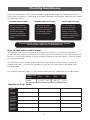
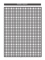
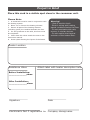
Affordable Underfloor Heating
Underfloor Heating Cable
Installation Manual
Technical Helpline 0845 034 8272
Before You Begin Installation...
Compatible floor finishes
The SunStone heater is intended to warm stone or tile floors.
The Right Measurements
You should have the correct room dimensions, size and number of heaters for the job. Note that
a cut heating cable cannot be returned.
Heater
Length
Code
Area
covered
Wattage @ 230Vac
SSW300
SSW450
SSW600
SSW750
2
3
4
5
300W
450W
600W
750W
25.5m
38.0m
51.0m
63.5m
sqm
sqm
sqm
sqm
Amperage
@ 230Vac
1.30A
1.96A
2.61A
3.26A
The Necessary Tools
This box includes a heating cable, fixing tape, primer and roller. Also required:
- THERMOSTAT WITH FLOOR SENSOR
- RCD as required for all installations
- Multi-meter for testing the resistance of the wires
- Electrical housing for connection leads, junction boxes and 35mm deep back box for the thermostat
- Permanent marker, measuring tape and scissors for the tape
Electrics
As all electrical work must comply with the current IEE Wiring Regulations, we strongly
recommend that you do not take on any electrical work unless qualified to do so.
General Precautions
What To Do
What Not To Do
Plan the heater layout and installation so
that any drilling after tiling (eg for fixing
sanitary ware) will not damage the wiring.
Cut or shorten the heating wire ever
Use flexible ceramic tile adhesives and
grouts suitable for use with undertile
heating
Store tiles or other sharp or heavy objects
on the heaters while tiling
Walk over an installed heater as this can
cause damage
Install the heating up walls or up a set of
stairs
Wait at least 10 days for the tile adhesive
to dry before switching the system on for
the first time
Install heating wires under units with solid
bases or built-in furniture
Only connect the heating wires in parallel
and maintain consistent spacing
Overlap heaters in case of overheating
Position the floor sensor or power lead on
or beneath the heating element
Test the system before, during and after
installation
2
About The SunStone Heater
Floor Sensor:
For the thermostat and heating
system to work properly,
installation must be correct.
Before embedding in adhesive,
position the sensor at least 150mm
into the heated area, exactly
between two runs of heating
element. Keep the sensor tip away
from drafts, sunlight, radiators, hot
water pipes or other sources of heat
fluctuations.
Wire Composition:
Element Core
Insulation
Metallic Earth Braid
Heater Layout:
PVC Insulation
Floor
Sensor
Joint
Power Lead
(to thermostat)
Evenly
spaced
Heating
Wire
Sticky Tape
keeps wire
in place
The joint which connects the heater wire and power lead must be installed under the tiles.
It may be necessary to cut a small groove in the subfloor to allow for the extra thickness of the
power lead and floor sensor.
Adapting the heater to room shapes
The heater is flexible enough to follow the shapes of units, so that the maximum area of coverage
is achieved. Take care not to damage the wire in any way. If you believe you have cut the wire,
call the helpline immediately.
REMEMBER!
If you have any question regarding the installation of
your heater, please call the helpline on 0845 034 8272.
3
Electrics
RCD Requirement
A dedicated 30mA RCD is compulsory and each thermostat must be protected by a fused spur.
Combination RCD/fused spurs should be used if the electrical circuits are not protected by a RCD.
It is possible to run the heater(s) from an existing circuit but check with an electrician if the circuit is RCD protected and can handle the load.
Electrical housing
A 35-40mm deep backbox is required for the thermostat and if more than two heaters are being
installed, a junction box will also be needed. The wiring from the heater to the thermostat should
be chased into the wall and protected by conduit or plastic trunking.
Thermostat connection
To install, follow the instructions in the thermostat box. Connect the thermostat to the main electrical supply via a fuse or circuit breaker according to wiring regulations. The thermostat should
be installed within the room or area to be heated, except where electrical regulations prohibit eg.
within the bathroom itself. In such cases, the thermostat should be fitted to the outside of an
internal wall of the bathroom, as near to the heating power supply wires as possible.
Wiring Overview:
Mains Power
Fused Spur
/ RCD
Thermostat
3-core cable
Junction
Box
Power Leads
Floor Probe
Heating
Cable=
4
Heating
Cable=
Checking Resistances
Check the resistances of your heater AT LEAST THREE TIMES during the installation process to
ensure that it is working. This is best done before installation work begins, while fixing the heater
and just before tiling.
BEFORE INSTALLING
DURING INSTALLATION
AFTER INSTALLING
Check the resistance
of each heater in case
damage had occurred
during the freight.
Note the resistances
in the table provided
below.
When each heater
has been fixed to the
subfloor, test again
for damage occurred
during installation.
To check that no
damage has been
done during the
setting of the tiles,
test once more after
the floor covering has
been put down.
If you are unsure of your readings or think that there is a problem,
call the helpline right away on 0845 034 8272.
How to test with a multi-meter
We recommend the use of a digital multi-meter set to a range of 0-2k ohms for testing the
heaters and 20k -200k for testing the floor sensor. Please note that due to the high resistance of
the wire, it may not be possible to get a continuity reading and for this reason, continuity testers
are not recommended.
The resistance (ohms) of each heater should be measured from the live (brown) wire to the
neutral (blue) wire. Jot down the readings you get from the multi-meter in the blank chart
provided below.
The readings should be within +/- 5% of these measurements: resistances in the table below.
Heater size
(sqm)
300450600750
ohms
176.9117.388.1 70.6
Results of Your Tests
Heater
No.
Size of
Heater
“Proper”
Reading
Reading
(No.1)
Reading
(No.2)
Reading
(No.3)
5
Preparations
SUBFLOORS
Follow these techniques for your subfloor type to ensure a rigid base. Then on a clean, dust and
grease-free floor, paint with the primer. Allow to dry for 3 hours; the colour should change from
light to dark green when dry. Do not prime on insulated tile backer board or existing ceramic/
quarry tiles.
Wooden Subfloors
Allow sufficient underfloor ventilation.
Pre-levelling existing floorboards with a latex/cement self-levelling compound will give a flush,
secure fit for the subsequently applied WBP plywood.
Seal the backs and edges of the plywood according to BS 5385:Part 3. clause 14.4.
To achieve a floor stable enough for accepting tiles, fit tongue and groove flooring and then overboard with ply or tile backer board.
The above recommendations apply to small floor areas as advised in clause 14.4 of BS 5385: Part
3:2007.
Concrete Subfloors
Extruded polystyrene tile backer boards with cement-based facing yield the best results. Follow
manufacturer’s instructions for fixing.
Once the board is attached to the subfloor, the heating system may be laid right on top of the
board, and then tiled over. Use high-quality, cement-based flexible tile adhesive and grout.
HEATER LAYOUT
1. Show key locations on subfloor with permanent marker
•
•
•
Designated spots of units and fixtures. Do not install the heater in any of these areas.
Positions of the power lead cables and the floor sensor.
Points where the wires will need to be turned when laid.
Please refer to page 8 for possible layouts and wire spacings.
2. Mark a start point
Mark up a start point as close as possible to the power supply, but no further than 2.5m from it.
3. Check resistances
Perform test #1 for each heater as explained in this manual.
4. Dry fit the heater(s)
Lay the wires out according to your plan so you can still make any last minute adjustments in the
layout before fixing them. Avoid stepping on or kinking the heater to prevent wire fracture.
Time Allowance
After installation, you must allow the tile adhesive and any self-levelling used to cure naturally
before powering-up the heating system. This takes 10-14 days depending on the amount of
materials used. Failure to await the correct length of time may result in damage to the system
and may also cause the adhesive and grout to dry too quickly, hence becoming brittle, leading to
tiles lifting and/or cracking.
6
Installations
Heater Installation
1. Fit the Heater(s)
Starting at the point where the power supply cable joins the heating wire, gently unreel the
cable and lay wire out around the perimeter. Only lay the wires in parallel lines.
Note : Ensure that all of the heating element including the joints are covered in
adhesive and tiled over. Do not tape over the joints as this will create air pockets.
2. Install Floor Sensor
The floor sensor that comes with the thermostat should now be placed centred between two
runs of heating elements and secured in place using double-sided tape. Now check the resistance of the floor sensor using your multi-meter. You may need to change the setting on your
meter in order to accommodate for the higher readings. If you do not get a reading, your
sensor may be damaged. If so, call the helpline for a replacement.
3. Fit the Power Leads
Each heater has a single power lead for connecting the system to the thermostat. To keep
the power leads at the same height as the heating element, a channel can be created in the
subfloor. Take care not to damage the heating wire. Tape the leads in place.
4. Install Thermostat
Instructions for fitting the thermostat can be found in the thermostat box.
5. Check resistances again
Perform test #2 for each heater as explained on page 5.
Tiling
When all your heaters are installed and the power leads and floor sensor have been fixed,
begin laying your tiles using one of two methods:
One-Step Method:
Apply a thick layer (5-10mm) of tile adhesive directly onto the heaters and lay the tiles onto
the adhesive layer.
Dual-Step Method:
1. Completely cover the heating wires with a smooth layer of flexible adhesive or latex selflevelling compound and allow to dry; it will normally take 1 day per mm.
2. Apply a thin layer (3mm) of flexible adhesive and tile as normal.
To
•
•
•
•
decide on which method, consider the following:
It is easier to lay mosaic tiles using the dual-step method
If this is your first installation, you may find it easier to use the dual-step method
If the floor will not be tiled right away, the dual-step method offers better wire protection
The one-step method is usually used by experienced installers of this heating system
Check final resistances
Perform test #3 for each heater as explained in this manual.
7
Positioning the Heater
Use the example guides below to work out where the wires are to be placed.
The wires must only be used in the lengths supplied and must not be cut or joined.
When laying more than one heater, do not allow the heating wires to touch or cross. Only join
heaters in parallel, NOT in series.
For best efficiency, space the wires equally (refer to spacing guide below).
Two or More Heaters in
Room with Fixtures
Single Heater in Regular Room
Use the following calculation to work out the cable spacing.
Floor Area (m²) x 1000
______________
Length of heater cable
= wire Spacing
Heater Spacing Guide
Area (m²)
Spacing (mm)
75
100
90
110
100
110
100
110
1.5
2.0
2.5
3.0
3.5
4.0
4.5
5.0
Always allow at least 50mm between wires at all times and at least 40mm between wires and
walls.
8
Heater Layout
9
Product Warranty
......................................................................................................................
YOUR STATUTORY RIGHTS WILL REMAIN UNAFFECTED BY THIS WARRANTY.
This SunStone undertile heater is guaranteed against any manufacturing defect for 10 years
starting from date of purchase.
This warranty covers the cost of replacement or repair of the SunStone undertile heater only,
subject to the discretion of the manufacturer.
This is the sole warranty, express or implied. The manufacturer or its agents cannot be held liable
for any resultant damages.
Send the completed form back to: SunStone Warranty, BCR House, 3 Bredbury Business Park,
Stockport, SK62SN
Proof of purchase is needed in the event of a claim, so keep your invoice with this warranty
This warranty is subject to the following conditions:
1. This warranty must be registered.
2. The heater must have been installed and used in full accordance with the installation manual.
3. The heater must have been earthed and protected by an RCD at all times.
4. The heater is used in conjunction with a thermostat or control system approved by SunStone.
5. The warranty is returned to SunStone within 30 days of purchase of the heater(s).
7. If SunStone or its agents carry out diagnostic or remedial work as a result of a claim being
made, agents shall have the right to levy reasonable charges for the work undertaken by them.
8. All electrical regulations are complied with and electrical work is undertaken by a
qualified and Part P certified electrician.
This warranty does not cover heater failure due to incorrect installation or tiling. Please
check that the heater is working (as laid out in the installation manual) prior to tiling.
Name
Address
Postcode
Telephone
Email
Installer
Electrician
Date of purchase
Room the heating system is installed:
Subfloor type (Concrete/Wood etc):
Signed:
Date:
Project in Brief
Place this card in a visible spot close to the consumer unit.
Please Note:
1. A 30mA RCD must be used in conjunction with
the heating system.
2. Never cut or shorten the heating element
3. Ensure all parts of the heating element
(including joints) are installed beneath the tiles.
4. For the guarantee to be valid, this form must
be completed.
5. Check that the values match the ones in the
instruction manual.
6. Draw a plan showing the layout of the heater
Warning!
– Risk of electric shock
- Electric wiring and heating
panels contained below the floor.
- Do not penetrate with nails,
screws, or similar devices.
- Do not restrict the thermal
emission of the heated floor.
Heater Location
Resistance Value
Attach label with heater description here
Before Installation:
_____________ohms
After Installation:
_____________ohms
Signature
Date
Electrician’s Part P registration no. Company stamp/name
Affordable Underfloor Heating
SunStone Underfloor Heating
Tel: 0845 034 8272
v1.0 05/12