1
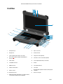
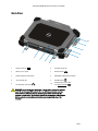
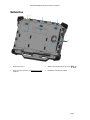
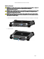
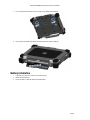
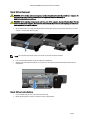
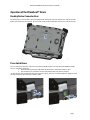
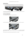
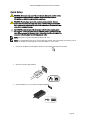
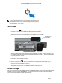
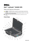
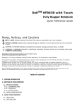
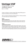
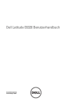
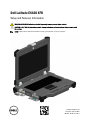
Dell Latitude E6420 XFR
Setup and Features Information
WARNING: A WARNING indicates a potential for property damage, personal injury, or death.
CAUTION: A CAUTION indicates either potential damage to hardware or loss of data and tells you how to avoid
the problem.
NOTE: A NOTE indicates important information that helps you make better use of your computer.
Regulatory Model: P21G
Regulatory Type: P21G001
MKW58 A01-00 June 2011
Dell Latitude E6420 XFR Setup and Features Information
Front View
1
2 3
1
4
21
20
19
18
5
6
7
17
16
15
13
12
11
10
9
8
14
1
Microphones (2)
12
Express card slot
2
Display latch
13
Audio connector
3
Camera (optional) and camera status light
14
Fingerprint reader (optional)
4
Direct Vue™ outdoor-readable display (optional
touchscreen)
15
Contactless smart-card reader (optional)
5
Power button
16
Secure Digital (SD) memory-card reader
6
eSata/USB connector
17
Handle
7
HDMI connector
18
Touch pad buttons (2)
8
Volume control buttons
19
Touch pad
9
Wireless switch
20
Backlit Keyboard (optional rubber backlit keyboard
available)
10
USB connectors (2)
21
Device status lights
11
Media bay modules (optical drives, second hard drive,
second battery, USB 3.0, legacy I/0 module)
Page 2
Dell Latitude E6420 XFR Setup and Features Information
Back View
10
9
8
1
7
6
2
3
1
Power connector (
2
5
6
Serial port connector
Battery access panel
7
VGA connector (
3
Power and battery status lights
8
QuadCool™ sealed thermal chamber
4
Security cable slot
9
Hard Disk Drive (
10
Enclosed Smart-card reader
)
(see Smart Cards) (
5
)
4
RJ-45 network connector (
)
)
)
WARNING: Do not block, push objects into, or allow dust to accumulate in the air
vents. Do not store your Dell computer in a low-airflow environment, such as a
closed briefcase, while it is running. Restricting the airflow can damage the
computer or cause a fire. The computer turns on the fan when the computer gets
hot. Fan noise is normal and does not indicate a problem with the fan or the
computer.
Page 3
Dell Latitude E6420 XFR Setup and Features Information
Bottom View
1
2
3
1
4
1
Battery latch release
3
Sliding cover to docking device connector (
2
RF pass-through connectors (see RF Pass-through)
(optional)
4
QuadCool™ sealed thermal chamber
Page 4
)
Dell Latitude E6420 XFR Setup and Features Information
Battery Removal
WARNING: Before working inside your computer, read the safety information that shipped with your computer. For
additional safety best practices information, see the Regulatory Compliance Homepage at
www.dell.com/regulatory_compliance.
WARNING: Using an incompatible battery may increase the risk of fire or explosion. Replace the battery only with a
compatible battery purchased from Dell. The battery is designed to work with your Dell computer. Do not use a
battery from other computers with your computer.
WARNING: Before removing or replacing the battery, turn off the computer, disconnect the AC adapter from the
electrical outlet and the computer, disconnect the modem from the wall connector and computer, and remove any
other external cables from the computer.
1.
Release the rear panel by pushing the slide latch to the right. If the secondary latch is engaged, press in to disengage.
2.
Lower the rear panel.
Page 5
Dell Latitude E6420 XFR Setup and Features Information
3.
Press outward on the two battery release latches on the bottom of the computer.
4.
Use the tab on the bottom of the battery to remove the battery from the computer.
Battery Installation
1.
2.
3.
Insert battery until you hear a click and a mechanical stop.
Rotate the door into place.
Ensure the door is in the fully closed and locked position.
Page 6
Dell Latitude E6420 XFR Setup and Features Information
Hard Drive Removal
WARNING: Before working inside your computer, read the safety information that shipped with your computer. For
additional safety best practices information, see the Regulatory Compliance Homepage at
www.dell.com/regulatory_compliance.
WARNING: Before removing or replacing the hard drive, turn off the computer, disconnect the AC adapter from the
electrical outlet and the computer, disconnect the modem from the wall connector and computer, and remove any
other external cables from the computer.
1.
Open the hard drive access slide-latch door located on the left side panel by pushing the latch towards the rear of the
computer, and rotate door down and open.
NOTE: See hard drive removal instructions on the sticker on the front face of the hard drive.
2.
3.
Press in the blue locking button on the right side of the compartment.
While pressing in the blue locking button, use the tab in the center of the hard drive to pull the hard drive from the
compartment.
Hard Drive Installation
1.
2.
Insert hard drive until you hear a click and a mechanical stop.
Rotate the door into place and press until it clicks into its closed position.
Page 7
Dell Latitude E6420 XFR Setup and Features Information
Operation of the PrimoSeal™ Doors
Docking Device Connector Door
The docking device connector door is opened by sliding the door towards the front of the computer to its fully open position.
Reverse this procedure to close the door. Be sure the door is fully closed by sliding door until it reaches a mechanical stop.
Press-Latch Doors
There are three press-latch doors. Two on the back (power and RJ45) and one on the right side panel (HDMI and eSATA).
The press-latch door is opened by:
a. Unlock the door by pushing the slide-lock to the left (the latch is locked when slid to the right)
b. Open the door by pressing down on the latch and pulling the door away from the computer.
To close the door, rotate the door back towards the computer and press until it is in its fully closed position. Engage the slidelock by pushing to the right until the lock symbol is visible.
Lock
Page 8
Dell Latitude E6420 XFR Setup and Features Information
Slide Latch Doors
There are three slide-latch doors on the unit, two on the left side and one on the right side. To open the slide-latch doors:
a. Ensure the door is unlocked by pushing the slide-latch in (the latch is locked when slid outward from the system)
b. Open the slide-latch door by sliding the latch towards the rear of the computer, and then rotating the door down.
Lo
ck
To close the door, rotate the door back into its closed position and press until you hear it click into position. If desirable, lock the
slide-latch door by pulling the slide-latch out.
Front Secure Digital Door
The secure digital door is located at the front of the computer behind the handle.
To open the secure digital door, slide the latch to the left to open. To close, slide the latch to the right until it clicks into place.
The Secure Digital card can be fully inserted, allowing the protective door to be closed. Insert the card into the secure digital slot
until it is fully seated in its connector. To release the secure digital card, press in on the card edge and the reader will eject the
card.
Reverse the procedure to close the protective door, pulling the handle until it is in its lock position.
Page 9
Dell Latitude E6420 XFR Setup and Features Information
Quick Setup
WARNING: Before you begin any of the procedures in this section, read the safety
information that shipped with your computer. For additional best practices
information, see www.dell.com/regulatory_compliance.
WARNING: The AC adapter works with electrical outlets worldwide. However,
power connectors and power strips vary among countries. Using an incompatible
cable or improperly connecting the cable to the power strip or electrical outlet may
cause fire or equipment damage.
CAUTION: When you disconnect the AC adapter cable from the computer, grasp
the connector, not the cable itself, and pull firmly but gently to avoid damaging the
cable. When you wrap the AC adapter cable, ensure that you follow the angle of the
connector on the AC adapter to avoid damaging the cable.
NOTE: Some devices may not be included if you did not order them.
NOTE: It is recommended that you turn on and shut down your computer at least once before you install any cards or
connect the computer to a docking device or other external device, such as a printer.
1.
Connect the AC adapter to the AC adapter connector on the computer and to the electrical outlet.
2.
Connect the network cable. (optional)
3.
Connect USB devices, such as a mouse or keyboard. (optional)
Page 10
Dell Latitude E6420 XFR Setup and Features Information
4.
Open the computer display and press the power button to turn on the computer.
NOTE: It is recommended that you turn on and shut down your computer at least
once before you install any cards or connect the computer to a docking device or
other external device, such as a printer.
Smart Cards
There are two main types of Smart or Common Access Cards (CAC):
1.
Enclosed Smart Cards (
) — these cards have a contact area with many gold plated connection pads. When
inserted into a card reader, the information from the chip can be read and written.
The Enclosed Smart Card is accessed through the left front side door above the hard drive.
Enclosed smartcard reader
The Smart Card can be fully inserted, allowing the protective hinged door to be closed. Insert the card into the smart
card slot with the gold contact pad facing upward and pointing toward the smart card slot. Slide the card into the slot
until it is fully seated in its connector.
Pull the smart card from the bottom to remove.
2.
Contactless Smart Cards (
) — these cards do not require any physical contact with the reader. The chip
communicates with the card reader through RFID induction technology. These cards require only close proximity to an
antenna of a card reader to complete transactions.
The Contactless Smart Card access is provided to the right of the keyboard touch pad.
RF Pass-Through
In the event the computer has an integrated WiFi and/or Broadband radio, the RF signals can be passed through a docking station
to external TNC antenna connectors (LAN/WAN/GPS). This supports the connection and use of external, vehicle-mounted
antennas (purchased separately) for improved radio performance.
Page 11
Dell Latitude E6420 XFR Setup and Features Information
Direct Vue™ Touch Display Information
The computer provides an optional touch screen display for entering and selecting data using an approved pointing device such
as your finger, a passive stylus or any non-abrasive smooth blunt object that will not damage the touch display.
NOTE: To ensure you properly care for and maintain your touch display, adhere to the care instructions regarding the
display.
WARNING: The optional Direct Vue TM Touch Display has been designed to accept finger touch as well as
passive stylus input directly onto the screen. With the optional Direct VueTM Touch Display, a stylus
is included with the computer for use in selecting items on the touch screen. Other pointing devices can be used
with the touch screen such as any non-abrasive, smooth or blunt object that will not damage the touch screen
display. The touch screen surface can be damaged by ink pens, marker pens or other pointed or abrasive objects.
The use of non-approved input devices that cause damage to the digitizer or LCD may not be covered by the limited
warranty.
The touch screen is pre-configured and pre-calibrated at the factory, but may require further calibration to improve accuracy for
entering or selecting data on the touch display. Please see the Tools section for information on Calibrating your Touch Display
and using your stylus.
Accessing Drivers and Documentation
Your Direct Vue Touch Display’s drivers, touch-input parameters and documentation have been pre-loaded at the factory. For
experienced users or IT administrators - if you need to re-install drivers, set up your Touch Display or modify parameters please
refer to the pre-loaded eGalaxTouch utility documentation for detailed instructions and refer to the summary provided in
eGalaxTouch Configuration Utility.
You can launch the pre-loaded documentation by selecting Start -> All Programs -> eGalaxTouch -> Document.
eGalaxTouch Configuration Utility
Your Direct Vue Touch Display system incorporates EETI technology. eGalaxTouch is a software utility tool that allows you to
configure various touch features.
You can launch eGalaxTouch by clicking Start -> All Programs -> eGalaxTouch -> Configure Utility.
NOTE: The touch screen is pre-configured and pre-calibrated at the factory, but may require further calibration to
improve accuracy for entering or selecting data on the touch display, or to further configure it to your specific application.
Please refer to the pre-loaded documentation for the eGalaxTouch configuration utility for a complete description of all its
capabilities and functionality.
You can launch the pre-loaded documentation for the eGalaxTouch Configuration Utility by selecting Start -> All Programs
-> eGalaxTouch -> Document -> User Guide for Windows 2000/XP/Vista -> eGalaxTouch Utility.
The eGalaxTouch utility consists of tabs that allow you to determine the best settings for your touch screen configuration.
•
•
•
•
•
•
•
The General tab shows all of the touch screen controllers installed in your system
The Tools tab provides access to calibration and touch position tools.
The Setting tab provides access to the configuration of beeps, clicks and mouse emulation as well as selection of 9
point or 25 point calibration for linearization.
The Display tab provides the tools for mapping the touch screen area to specific areas of the display. The default is
full screen.
The Edge Parameters tab provides configuration for selecting items near the edge of the touch screen.
The Hardware tab provides the model and firmware version of the touch screen controller.
The About tab provides the version of the driver as well as providing a link for downloading the latest driver.
Page 12
Dell Latitude E6420 XFR Setup and Features Information
General
The general property page shows all the eGalaxTouch touch screen controllers installed including RS232, USB and PS2
interfaces. The touch screen controller is a USB device.
Tools
The Tools property page provides the following information and functions.
NOTE: Your touch screen is configured and calibrated at the factory. However, if you notice that the calibration is not as precise
as you would like, you can use the 4 Points Calibration and/or the Linearization tool to provide a more accurate alignment of the
touch screen.
•
•
•
•
•
Graph of the Linearization Curve of the touch screen: For reference and troubleshooting purposes. See its usage in
the discussion of the Linearization function.
4 Points Calibration: Calibration aligns the touch panel with the video screen. The touch screen must be calibrated to
allow for positional accuracy of the stylus or finger touch inputs.
Clear and Calibrate: Clears the calibration/linearization parameters and allows you to perform the 4 points calibration
again.
Linearization (9 or 25 points linearization is set within the Setting tab): The linearization function provides for more
precise mapping of the stylus or finger touch inputs. After linearization is completed, the linearity of the touch screen
will be shown in the Linearization Curve window.
Draw Test: Used for accuracy and performance checking.
1. 4 Points Calibration
The touch screen must be calibrated before it can work accurately. This function pops up a new window to guide you
through the 4 points calibration. You should follow the guide to touch and hold the blinking X symbol in the calibration
window until it does not blink to make sure that the utility can gather enough data for computation. In addition, a time line bar
is shown in the bottom of the window to indicate time elapsed. If the touch screen is not touched before the time line bar
reaches the right end, the calibration task will be terminated automatically.
2.
Linearization
This function provides for more accurate touch screen positional alignment. The linearization function pops up a new
window to guide you through the 9 or 25 points calibration. Configuring the function for 9 or 25 points calibration is accessed
in the Setting tab. You should follow the guide to touch and hold the blinking X symbol in the calibration window until it
does not blink to make sure that the utility can gather enough data for computation. In addition, a time line bar is shown in the
bottom of the window to indicate the time elapsed. If the touch screen is not touched before the time line bar reaches the
right end, the calibration task will be terminated automatically.
3.
Draw Test
This function is used for accuracy and performance checking. You can use the stylus or finger touch to draw or write across
the displayed area.
You can press the Clear button to clear the window. Press the Quit button to terminate the draw test.
Setting
The Setting property page provides the following buttons and check boxes:
1.
Beep
•
Beep On Touch
Check this check box to enable driver to generate a beep sound when touch touchscreen state is switched from
untouched to touched state.
•
Beep On Release
Check this check box to enable driver to generate a beep sound when touchscreen state is switched from
touched state to untouch state.
•
Frequency
Adjust this frequency to control the beep sound frequency generated by the driver.
•
Duration
Adjust this duration to control the beep sound duration.
Page 13
Dell Latitude E6420 XFR Setup and Features Information
2.
Linearization Style
The eGalaxTouch utility provides you with both 9 points and 25 points calibration for linearization. You can select the
suitable kind of linearization type with this setting. The Linearization function is accessed under the Tools tab.
3.
Double Click Time
The double Click Time group is used to set system double click time. Changing this value will affect the double click
behavior for all of the mice devices in the system. Two continuous clicks at the same area within this specified time
period will be recognized as a double click event.
4.
Double Click Area
The double click area group is used to set the system double click area. Changing this value will affect the double click
behavior for all of the mice devices in the system. Two continuous clicks within the specified area in the specified
double click time will be recognized as a double click event.
5.
Mouse Emulation mode
There are 5 mouse emulation modes for the eGalaxTouch touch screen controllers. Press on the button to change the
emulation mode.
•
Normal Mode
You can select this mode to select objects, and drag objects.
•
Click On Touch
With this Click On Touch mode, the driver emulates a mouse click event when the touch screen state is switched
from un-touched state to touched state. Then, the driver always generates a mouse move event and tracks the
touch position until the touch screen state switches to the un-touch state.
•
Click On Release
With this Click On Release mode, the driver emulates a mouse click event when the touch screen state is
switched from touched state to un-touched state.
•
Click On Touch without moving cursor
With this mode, the driver behaves similarly to the Click On Touch mode. The cursor does not move to the touch
position except for the first touch point.
•
Click On Release without moving cursor
With this mode, the driver behaves similarly to the Click On Release mode. The cursor does not move to the touch
position except for the lift-off point.
6. Option
You can access advanced configuration functions with the Option button. Press the button, and the following window will
appear.
Display
The eGalaxTouch driver supports multiple monitor and display systems. To work with multiple monitor systems, you need to
perform the proper configuration to map the touch screen working area to the correct system display area using the Display
property page.
Edge Parameters
For some special touch screen applications where the edge area of the full screen cannot be reached, eGalaxTouch provides you
with this edge compensation tool to solve the problem and allow for touching the edge area without accuracy loss.
Hardware
The Hardware property page shows the model and firmware version of the eGalaxTouch controller. The software will query the
hardware information from the controller and show the information as illustrated here.
About
The About property page shows information regarding the eGalaxTouch driver, including providing a link to allow you to download
the latest driver.
Page 14
Dell Latitude E6420 XFR Setup and Features Information
Specifications
NOTE: Offerings may vary by region. The following specifications are only those
required by law to ship with your computer. For more information regarding the
configuration of your computer, click Start → Help and Support and select the
option to view information about your computer.
System Information
Chipset
Intel Mobile Express Series 6 chipset
DRAM bus width
64-bit
Flash EPROM
SPI 32 Mbits
PCIe Gen1 bus
100 MHz
Processor
Types
• Intel Core i3 series
• Intel Core i5 series
• Intel Core i7 series
L2 cache
Up to 6 MB
External bus frequency
1333 MHz
Memory
Memory connector
Two SODIMM slots
Memory capacity
1 GB, 2 GB, or 4 GB
Memory type
DDR3 SDRAM (1333 MHz)
Minimum memory
2 GB
Maximum memory
8 GB
Audio
Type
four-channel high definition audio
Controller
IDT 92HD90
Stereo Conversion
24-bit (analog-to-digital and digital-to-analog)
Interface:
Speakers
Internal
high definition audio
External
microphone-in/stereo headphones/external speakers connector
two
Page 15
Dell Latitude E6420 XFR Setup and Features Information
Audio
Internal speaker amplifier
0.5 W (typical) per channel
Volume controls
keyboard function keys, program menus
Video
Video type
• integrated on system board
• discrete
Data bus
UMA
integrated video
Discrete
• PCI-E x16 Gen1
• PCI-E x16 Gen2
Video controller
UMA
Intel® HD Graphics 3000
Discrete
NVIDIA®NVS™4200M Discrete Graphics (512 MB DDR3)
Output
• 15-pin VGA connector
• 19-pin HDMI connector
Communications
Network adapter
10/100/1000 Mbps Ethernet LAN
Wireless
internal wireless local area network (WLAN) and wireless wide area network (WWAN)
Ports and Connectors
one microphone connector/stereo headphones/ external speakers connector
Audio
WARNING: Excessive sound pressure from earphones and headphones can
cause hearing loss.
Video
• one 15-pin VGA connector
• one 19-pin HDMI connector
Network adapter
one RJ-45 connector
USB
two 4-pin USB 2.0-compliant connectors,
one eSATA/USB 2.0-compliant connector
Serial
one DB9 pin serial (RS232)
Memory card reader
one 5-in-1 memory card reader
Display
Type
white Light Emitting Diode (WLED) display
Size
14.0 inch high definition (HD)
Active area (X/Y)
309.4 mm x 173.95 mm
Page 16
Dell Latitude E6420 XFR Setup and Features Information
Display
Dimensions:
Height
192.50 mm (7.58 inches)
Width
324.00 mm (12.76 inches)
Diagonal
355.60 mm (14.00 inches)
Maximum resolution
1366 x 768
Maximum Brightness
730 nits
Operating angle
0° (closed) to 135°
Refresh rate
Minimum Viewing angles:
60 Hz
Horizontal
+/- 50°
Vertical
+/- 40°
Pixel pitch
0.2265 mm
Keyboard
Number of keys
United States: 86 keys, United Kingdom: 87 keys, Brazil: 87 keys, and Japan: 90 keys
Layout
QWERTY/AZERTY/Kanji
Touchpad
Active Area
X-axis
80.00 mm
Y-axis
40.70 mm
Battery
Type
• 6-cell “smart” Lithium ion
Dimensions
Weight
Depth
48.08 mm (1.89 inches)
Height
20.00 mm (0.79 inch)
Width
208.00 mm (8.19 inches)
344.73 g (0.76 lb)
Page 17
Dell Latitude E6420 XFR Setup and Features Information
Battery
Charge time with computer
off (with 90 W adapter)
approximately 1 hour to 80% capacity and 2 hours to 100% capacity.
Voltage
11.10 VDC
Temperature range:
Operating
0 °C to 60 °C (32 °F to 140 °F)
Non-Operating
–51 °C to 71 °C (–59 °F to 159 °F)
Coin-cell battery
3 V CR2032 lithium coin cell
AC Adapter
Type
90 W
Input voltage
100 VAC to 240 VAC
Input current (maximum)
1.50 A, 1.60 A, and 1.70 A
Input frequency
50 Hz to 60 Hz
Output power
90 W
Output current
4.62 A (continuous)
Rated output voltage
19.5 +/– 1.0 VDC
Temperature range:
Operating
0 °C to 40 °C (32 °F to 104 °F)
Non-Operating
–40 °C to 70 °C (–40 °F to 158 °F)
Physical
Height
56.80 mm (2.6 inches)
Width
356.1 mm (14.0 inches)
Depth
296 mm (11.7 inches)
Weight (solid state drive)
3.99 kg (8.8 lbs)
Page 18
Dell Latitude E6420 XFR Setup and Features Information
Environmental
Temperature:
Operating
0 °C to 35 °C (32 °F to 95 °F)
Storage
-51 °C to 71 °C (-59 °F to 159 °F)
Relative humidity
(maximum):
Operating
10 % to 90 % (noncondensing)
Storage
5 % to 95 % (noncondensing)
Altitude (maximum):
Operating
-15.2 m to 3048 m (-50 ft to 10,000 ft)
Operating with
SSD
-15.2 m to 4572m (-50ft to 15,000 ft)
Non-Operating
-15.2 m to 10,668 m (-50 ft to 35,000 ft)
Airborne contaminant level
G1 as defined by ISA S71.04–1985
Page 19
Dell Latitude E6420 XFR Setup and Features Information
Finding More Information and Resources
This section is the last part of the SFITS
See the safety and regulatory documents that shipped with your computer and the regulatory compliance website at
www.dell.com/regulatory_compliance for more information on:
• Safety best practices for your computer
• Warranty
• Terms and Conditions
• Regulatory
• Ergonomics
• End User License Agreement
Information in this publication is subject to change without notice.
© 2011 Dell Inc. All rights reserved.
Reproduction of these materials in any manner whatsoever without the written permission of Dell Inc. is strictly forbidden.
Trademarks used in this text: Dell™, the DELL logo, Dell Precision™, Precision ON™, ExpressCharge™, Latitude™, Latitude ON™,
OptiPlex™, Vostro™, and Wi-Fi Catcher™ are trademarks of Dell Inc. Intel®, Pentium®, Xeon®, Core™, Atom™, Centrino®, and
Celeron® are registered trademarks or trademarks of Intel Corporation in the U.S. and other countries. AMD® is a registered
trademark and AMD Opteron™, AMD Phenom™, AMD Sempron™, AMD Athlon™, ATI Radeon™, and ATI FirePro™ are
trademarks of Advanced Micro Devices, Inc. Microsoft®, Windows®, MS-DOS®, Windows Vista®, the Windows Vista start
button, and Office Outlook® are either trademarks or registered trademarks of Microsoft Corporation in the United States and/or
other countries. Blu-ray Disc™ is a trademark owned by the Blu-ray Disc Association (BDA) and licensed for use on discs and
players. The Bluetooth® word mark is a registered trademark and owned by the Bluetooth® SIG, Inc. and any use of such mark
by Dell Inc. is under license. Wi-Fi® is a registered trademark of Wireless Ethernet Compatibility
Alliance, Inc.
Other trademarks and trade names may be used in this publication to refer to either the entities claiming the marks and names or
their products, Dell Inc. disclaims any proprietary interest in trademarks and trade names other than its own.
MKW58 A01-00 June 2011
Page 20