1
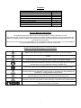
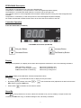
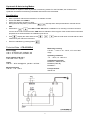
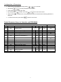
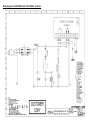
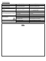
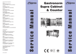
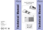
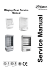
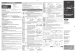
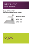
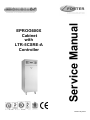
ISO 14001 Service Manual EPROG600X Cabinet with LTR-5CSRE-A Controller ISO 9001 Issued July 2010 Contents Manual Information & Health & Safety Notes Environmental Management Policy Disposal Requirements EPROG600X Description Controller Operation Configuration of Parameters Technical Data Cabinet Controller Default Wiring Diagram Troubleshooting & Notes 1 2 2 3 3 to 4 4 4 5 6 7 Service Manual Information The products and all information in this manual are subject to change without prior notice. We assume by the information given that the person(s) working on these refrigeration units are fully trained and skilled in all aspects of their workings. Also that they will use the appropriate safety equipment and take or meet precautions where required. The service manual does not cover information on every variation of this unit; neither does it cover the installation or every possible operating or maintenance instruction for the units. Health & Safety Warnings and Information Make sure the power supply is turned off before making any electrical repairs. To minimise shock and fire hazards, please do not plug or unplug the unit with wet hands. During maintenance and cleaning, please unplug the unit where required. Care must be taken when handling or working on the unit as sharp edges may cause personal injury, we recommend the wearing of suitable PPE. Ensure the correct moving and lifting procedures are used when relocating a unit. Do NOT use abrasive cleaning products, only those that are recommended. Never scour any parts of the refrigerator. Scouring pads or chemicals may cause damage by scratching or dulling polished surface finishes. Failure to keep the condenser clean may cause premature failure of the motor/compressor which will NOT be covered under warranty policy. Do NOT touch the cold surfaces in the freezer compartment. Particularly when hands are damp or wet, skin may adhere to these extremely cold surfaces and cause frostbite. Please ensure the appropriate use of safety aids or Personnel Protective Equipment (PPE) are used for you own safety. 1 Environmental Management Policy for Service Manuals and Duets. Product Support and Installation Contractors Foster Refrigerator recognises that its activities, products and services can have an adverse impact upon the environment. The organisation is committed to implementing systems and controls to manage, reduce and eliminate its adverse environmental impacts wherever possible, and has formulated an Environmental Policy outlining our core aims. A copy of the Environmental Policy is available to all contractors and suppliers upon request. The organisation is committed to working with suppliers and contractors where their activities have the potential to impact upon the environment. To achieve the aims stated in the Environmental Policy we require that all suppliers and contractors operate in compliance with the law and are committed to best practice in environmental management. Product Support and Installation contractors are required to: 1. Ensure that wherever possible waste is removed from the client’s site, where arrangements are in place all waste should be returned to Foster Refrigerator’s premises. In certain circumstances waste may be disposed of on the client’s site; if permission is given, if the client has arrangements in place for the type of waste. 2. If arranging for the disposal of your waste, handle, store and dispose of it in such a way as to prevent its escape into the environment, harm to human health, and to ensure the compliance with the environmental law. Guidance is available from the Environment Agency on how to comply with the waste management ‘duty of care’. 3. The following waste must be stored of separately from other wastes, as they are hazardous to the environment: refrigerants, polyurethane foam, and oils. 4. When arranging for disposal of waste, ensure a waste transfer note or consignment note is completed as appropriate. Ensure that all waste is correctly described on the waste note and include the appropriate six-digit code from the European Waste Catalogue. Your waste contractor or Foster can provide further information if necessary. 5. Ensure that all waste is removed by a registered waste carrier, a carrier in possession of a waste management licence, or a carrier holding an appropriate exemption. Ensure the person receiving the waste at its ultimate destination is in receipt of a waste management licence or valid exemption. 6. Handle and store refrigerants in such a way as to prevent their emission to atmosphere, and ensure they are disposed of safely and in accordance with environmental law. 7. Make arrangements to ensure all staff who handle refrigerants do so at a level of competence consistent with the City Guilds 2078 Handling Refrigerants qualification or equivalent qualification. 8. Ensure all liquid substances are securely stored to prevent leaks and spill, and are not disposed of to storm drains, foul drain, or surface water to soil. Disposal Requirements If not disposed of properly all refrigerators have components that can be harmful to the environment. All old refrigerators must be disposed of by appropriately registered and licensed waste contractors, and in accordance with national laws and regulations. 2 EPROG600X Description The cabinets are manufactured as a one piece foamed shell. Temperature is controlled by a microprocessor control with digital temperature display. The heated air is circulated the heater element, via the fan into the storage area. The cabinets conform to current legislation and exceed the Montreal protocol using zero ODP refrigerants and insulation Temperature is controlled by a LAE microprocessor control with digital temperature display. All models are fitted with lockable swivel castors to the front and swivel castors to the rear. Controller Operation Probe Air SN4K150P1 (00-556187) LTR-5CSRE-A Controller (00-556186) Set point Button. Increase Button. Decrease Button. Exit/Stand-by Button. Display During normal operation, the display shows either the temperature measured or one of the following indications: oFF Controller in stand-by or Probe T1 Out of range or failure TUN / 5.4 Controller in autotuning E1 In tuning: timeout1 error E2 In tuning: timeout2 error E3 In tuning: overage error Set point (display and modification of desired temperature value) Press button By keeping button pressed, use button for at least half second, to display the set point value. or to set the desired value (adjustment is within the minimum SPL and the maximum SPH limit). When button is released, the new value is stored. Stand-By Button , when pressed for 3 seconds, allows the controller to be put on a standby or output control to be resumed (with SB=YES only). In standard settings mode, this facility is disabled. 3 Hysteresis & Auto tuning Modes The controller is capable of either Hysteresis or Autotuning modes. For the FHC500X, the controller uses Hysteresis and therefore Autotuning is disabled and should not be reactivated. Recalibration Have a precision reference thermometer or a calibrator to hand. Ensure that OS1=0 and SIM=0. Switch the controller off then on again. During the auto-test phase, press buttons + , and keep them both pressed till the controller shows 0AD. With buttons or select 0AD or SAD: 0AD allows a calibration of 0, inserting a constant correction over the whole scale of measurement. SAD allows a calibration of the top part of the measurement scale with a proportional correction between the calibration point and 0. Press to display the value and then use + or to make the read value coincide with the value measured by the reference instrument. Exit from calibration by pressing button . Technical Data - LTR-5CSRE-A Measuring accuracy LTR-5C…: <±0.3°C -40…100°C; ±1°C out of that range Power supply LTR-5…E 230Vac±10%, 50/60Hz, 2W LTR-5…U 115Vac±10%, 50/60Hz, 2W Operating conditions -10 … +50°C; 15…80% R.H. Relay outputs (LTR-5..R..) LTR-5.SR.. OUT1 16(4)A CE (Reference Norms) EN60730-1; EN60730-2-9; EN55022 (Class B); EN50082-1 Inputs LTR-5C…: NTC 10KΩ@25°C, part No. LAE SN4... Measuring Range LTR-5C…: -40…125°C Front protection IP55 & VIA 4 Configuration of Parameters Setup menu is accessed by pressing buttons With button Press button By keeping button When button or + for 5 seconds. select the parameter to be modified. to display the value. pressed, use button or to set the desired value. is released, the newly programmed value is stored and the following parameter is displayed. To exit from the setup, press button or wait for 30 seconds. Default Parameter Values for Controller and EPROG600X LTR 5CSRE-A Parameter List Reg Parameter Description 233 SCL Readout scale 200 202 204 212 SPL SPH 1SP 1Y Minimum set point [ I ] Maximum set point [ I ] Set point [ I ] Control Type 212 1HY Change-over hysteresis [ I ] 214 1PB Proportional band 215 216 217 206 219 220 234 1IT 1DT 1AR 1CT 1PF BAU SIM Integral action time Derivative action time Reset of integral action Cycle time Status with faulty sensor Operation of auxiliary button Display slowdown 236 OS1 Sensor correction 235 ADR Unit address Min. Max 1°C / 2°C / °F -50 SPH SPL 150 SPL SPH HY PID 19.9 19.9 19.9 19.9 0 999 0 999 0 100 0 255 ON / OFF NON / SBY 0 100 12.5 12.5 1 255 5 EPROG600X Dim. Default flag 1°C 2°C °C °C °C flag -19.9 99.9 40 hy 83 90 87 HY °K -5 °C -5 sec. sec. % sec. flag flag flag 350 50 90 10 OFF NON 0 °K 0 flag 1 -3 6 1 4 15 20 OFF NON 3 0 1 Wiring Diagram for EPROG600X with LTR 5CSRE-A Controller 6 Troubleshooting Problem Possible Cause No display on the controller and red neon illuminated Safety thermostat tripped Unit not heating and the fan is not running No output from controller No output from the controller Unit not heating and fan is running Main on, neon not illuminated with unit switched on. Safety thermostat trips regularly Solution Reset and investigate cause. a. Check controller relay output b. Fan may be faulty c. Check the heater. Faulty relay Check controller relay output Check the heater and replace as necessary Check relay and replace as necessary Fuse blown in plug No electrical supply at the socket Check and replace if necessary Check socket Faulty Mains Lead Check & replace as necessary Fan running too slow Incorrectly set thermostat Check and replace as necessary Adjust as necessary Faulty heater Notes 7 Foster European Operations France Foster Refrigerator France SA Tel: (33) 01 34 30 22 22. Fax: (33) 01 30 37 68 74. Email: [email protected] Germany Foster Refrigerator Gmbh, Tel: (49) 781 990 7840. Fax (49) 781 990 7844. Email: [email protected] Foster Refrigerator Oldmedow Road Kings Lynn Norfolk PE30 4JU Tel: 0843 216 8833 Fax: 0843 216 4707 Website: www.fosterrefrigerator.co.uk Email: [email protected] a Division of ‘ITW (UK) Ltd’ EPROG CAB/ LTR5/SM 07/10 8