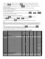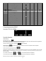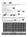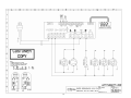
1
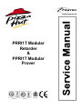
PRRI1T Modular
Retarder
&
PPRI1T Modular
Prover
ISO 14001
ISO 9001
Environmental Management Policy for Service Manuals and Duets.
Product Support and Installation Contractors
Foster Refrigerator recognises that its activities, products and services can have an adverse impact upon the
environment.
The organisation is committed to implementing systems and controls to manage, reduce and eliminate its adverse
environmental impacts wherever possible, and has formulated an Environmental Policy outlining our core aims. A
copy of the Environmental Policy is available to all contractors and suppliers upon request.
The organisation is committed to working with suppliers and contractors where their activities have the potential to
impact upon the environment. To achieve the aims stated in the Environmental Policy we require that all suppliers
and contractors operate in compliance with the law and are committed to best practice in environmental
management.
Product Support and Installation contractors are required to:
1. Ensure that wherever possible waste is removed from the client’s site, where arrangements are in place all
waste should be returned to Foster Refrigerator’s premises. In certain circumstances waste may be disposed
of on the clients site; if permission is given, if the client has arrangements in place for the type of waste.
2. If arranging for the disposal of your waste, handle, store and dispose of it in such a way as to prevent its
escape into the environment, harm to human health, and to ensure the compliance with the environmental law.
Guidance is available from the Environment Agency on how to comply with the waste management ‘duty of
care’.
3. The following waste must be stored of separately from other wastes, as they are hazardous to the environment:
refrigerants, polyurethane foam, oils.
4. When arranging for disposal of waste, ensure a waste transfer note or consignment note is completed as
appropriate. Ensure that all waste is correctly described on the waste note and include the appropriate six-digit
code from the European Waste Catalogue. Your waste contractor or Foster can provide further information if
necessary.
5.
Ensure that all waste is removed by a registered waste carrier, a carrier in possession of a waste management
license, or a carrier holding an appropriate exemption. Ensure the person receiving the waste at its ultimate
destination is in receipt of a waste management license or valid exemption.
6. Handle and store refrigerants in such a way as to prevent their emission to atmosphere, and ensure they are
disposed of safely and in accordance with environmental law.
7. Make arrangements to ensure all staff who handle refrigerants do so at a level of competence consistent with
the City Guilds 2078 Handling Refrigerants qualification or equivalent qualification.
8.
Ensure all liquid substances are securely stored to prevent leaks and spill, and are not disposed of to storm
drains, foul drain, surface water to soil.
DISPOSAL REQUIREMENTS
If not disposed of properly all refrigerators have components that can be harmful to the environment. All old
refrigerators must be disposed of by appropriately registered and licensed waste contractors, and in accordance
with national laws and regulations.
The materials used to package this refrigerator/coldroom may be recycled. Recycling will reduce the effect this
waste has upon the environment. For information on waste collection facilities in your area, and other advice on
recycling of packaging waste, visit www.recycle-more.co.uk
Contents
Page
2
2
3 to 7
7 to 10
10 to 11
11
12
13 to 14
1. Introduction
2. Specification
3. Panel Layout and Dimensions
4. Operating Instructions & Service Settings FPR2T
5. Operating Instructions & Service Settings FPP2T
6. Technical Data
8. Spare Parts List
9. Wiring Diagrams
1
1. INTRODUCTION
The two models are the PRRI1T, pizza dough retarder, and the PPRI1T pizza prove:
They are designed to accommodate two special pizza trolleys, not supplied.
The control system allows cabinet allows for simple manual operation with pre-set temperatures and function
indicator lights.
Each cabinet has a Micro Processor temperature controller complete with function indicator L.E.D.’s. The Prover
also has a process timer.
Standard Finish
Exterior walls.
Rear Wall
Front Wall.
Ceiling.
Door.
Interior Walls & Ceiling.
Sides.
Back
Front
Ceiling
Door
Base
Insulation thickness CFC Free polyurethane foam
75mm
Co-Laminate.
75mm
Co-Laminate.
75mm
Co-Laminate
100mm
Co-Laminate
50mm
Stainless Steel 304.
Floorless
Smooth Aluminium.
2. SPECIFICATION
2.1 Construction.
The product is of modular construction with the refrigeration system built onto an independent ceiling panel.
The door is a slab type with self-closing rising butt hinges. Complete with a full height handle and no locks.
Magnetic door gasket and a wiper gasket to the bottom edge of the door.
The door can be hinged left or right hand as required.
2.2 Internal Fittings
Two Trolleys per section. (Not supplied as standard)
Maximum size of trolley 430 x 760 x 1730mm.
The internal walls are protected with aluminium Bumper Bars.
2.3 Service Requirements.
Electrical Supply 230V, 1 phase, 50Hz.
Fuse rating 13 Amp.
2.4 Temperature Ranges.
The cabinet is designed to automatically process Pizza Dough from a frozen condition (-18°c / -21°c) to a finished
product as below.
Retard Temperature.
Prove Temperature.
+1°c/ +4°c.
28°c/ +32°c.
The cabinets conform to ISO Climate Class 5 (40°c ambient with 40% RH).
2.5 Air Flow.
Air is circulated through the evaporator coil, or in the case of the Prover across the heaters, and discharged
through a vented air duct fitted to the rear wall of the cabinet.
Internal airflow is generated by 3 x 10W motors with 200mm Ø, 34° pitch angle blades.
2.6 Retarding (Refrigeration).
The refrigeration system is a self-contained unit comprising of air-cooled condensing unit, forced air evaporator and
all ancillary parts and controls. The equipment is pre-charged with refrigerant and pre-wired to allow for easy
installation on site.
Refrigerant used is R134a.
The evaporator has a large surface area to provide high humidity during the retard operation.
Refrigerant control is a capillary based system used to control the correct amount of refrigerant required to meet
the demand of the evaporator.
2.7 Proving (Heating).
An electric heater assembly is mounted on the rear face of the cooling coil which is energised during the prove
process.
As an extra safety feature, a pre-set overheat thermostat switch is provided should the main control thermostat fail.
During the Thaw process both cooling and heating are used to ensure that the air temperature is controlled to
defrost the dough.
2
3. Panel Layout and Dimensions
3.1 Ceiling panel with the refrigeration system
3.2 Ceiling panel with heater assembly
3.3 Cabinet Dimensions
3
3.4 ‘U’ Channel Fitting
The ‘U’ channel is supplied cut to the correct lengths, use the cardboard template provided to position the channel
on the floor.
The external dimensions of the room are - 1200mm Wide X - 965mm Deep
It is important that the ‘U’ channel is fixed squarely so that the panels will lock together when inserted.
It is recommended that there should be no more than 3mm tolerance in the floor level as this can affect the correct
location of the locking panels.
Using a spirit level check floor level on all four sides.
If required use packing shims to take up any anomalies in the floor.
Once you are satisfied with the level the U channel can be rawl-plugged or hilti-nailed into position ensuring it is
sealed with silicone sealer between the floor and the channel to prevent moisture penetration.
Apply ‘mastic sealer’ to the inside of the channel so that when the panels are located there is a vapour seal.
4
3.5 ASSEMBLY OF WALL PANELS.
Note: there is no door header panel as this is integral with the ceiling panel.
Fit the side panel into the channel and apply a bead of mastic to the rear edge to create a vapour seal rear (see fig
1). Place the rear panel in the channel, these can now be locked together by means of the Foster Lock (see fig 2)
operated by the hexagon shaped key provided (see fig 3). All panels are locked internally.
Fig 1
Fig 2
Fig 3
3.6 FITTING THE CEILING PANEL.
At the top of the wall panels there is a recess that accepts the ceiling.
Apply mastic to the recess so that when the panel is fitted there is a good vapour seal.
Slacken the screws securing the front panel to the sides and lift away, taking care not to damage the
interconnecting cables, rest it securely on the top of the ceiling panel. See below.
Lift the ceiling panel complete and lower into the top recess.
With the ceiling panel in place slide the galvanised angle bracket into place (see fig 4). Secure in place using the
screws provided (see fig 5 and 6).
5
Fig 4
Fig 5
Fig 6
With the ceiling panel secured in place seal the internal joints with silicone sealer.
Insert the buttons into the lock holes.
Note: For Prover models the fitting instruction is the same.
3.7 FITTING THE REAR AIR DUCT
1) Prior to fitting the rear air duct check that the Air Return Duct (A) is correctly located into the Coil Driptray
Flange (B), see fig 7.
2) Place the air duct against the rear of the cabinet and insert into the space between the air return duct and the
rear of the cabinet to a depth of 10mm, see fig 7, secure in place using the self tapping screws provided.
NOTE: For Prover models the rear air duct fitting is the same
Fig 7
Coil driptray
flange (B)
Air Return Duct (A)
Insert airduct
10mm into
aperture
Air Duct
Rear of
Cabinet
3.8 FITTING THE BUMPER BARS
Place the rear bumper bars against air duct and line up with the pre-drilled threaded holes in the duct, secure in
place using the M5 screws provided.
Place the side bumper bars against side panels lining them up with the pre-drilled holes, secure in place using the
self tapping screws provided.
6
3.9 FITTING THE DOOR
Check that the inserts are fitted correctly into the hinge parts attached to the cabinet (see fig 8).
Check that the insert for the door part of the hinges are correct for the door hinging, fig 9 shows the insert fitted for
right hand hinging.
Fig 8
Fig 9
Fig 10
Hold the door at a 90° angle to the cabinet and lower the door on to the hinges, see fig 10 for the correct hinge
alignment in the closed position. Check that it hangs squarely to the cabinet.
Re-fit the unit cover and check that the top of the door lines up with the bottom of it.
To remove the door reverse the process.
After hanging the door inspect the door gasket ensuring that seals fully to the doorframe.
Also ensure that the door wiper gasket, fitted to the bottom of the door (see fig 11).
Fig 11
4. Operating Instructions PRRI1T
LCD 28CS4E-B (00-555739) Controller
Operation Guidelines
LCD 16 Display (00-555740)
Initial Start Up.
Start Up & self Test:
The indication is only displayed during the first three seconds following the mains electrical power being applied to
the unit. During this period the controller performs a self-check.
Once the self-check has been completed
Press and hold
OFF
will be displayed.
for three seconds. The unit will start and the air temperature will be displayed.
Check temperature set point.
Important to note that the ability to increase and decrease the set point is not a function available to the user as the
set point is fixed. To make adjustments to the set point it is necessary to access the parameter and alter SPL and
SPH accordingly.
Check set point by pressing the button
7
To increase set point press
+
To decrease set point press
until required temperature is displayed.
+
until required temperature is displayed.
Factory Temperature Set Point
+1°c
Exit from set up occurs after 10 seconds if no button is pressed.
Manual Defrost.
To initiate a manual defrost press and hold
dEF
will be displayed release.
REC
On completion of the defrost
will be displayed until the cabinet temperature is achieved and then it will
revert to displaying the normal cabinet temperature.
Set Unit to Standby.
Press
OFF
display shows
Standby Indication
This indication is displayed while the unit is not operating but with mains power applied to the unit. This mode may
be used for internal cleaning regimes and short periods when the unit is not required.
For extended periods of inactivity the mains supply should be isolated.
Alarm and Warnings
High temperature alarm
HI
Will be displayed.
The alarm will sound but can be silenced by pressing any of the buttons, however it will return after the
pre-set designated period. The unit returning to normal operating temperature will automatically cancel the alarm.
Possible Causes: Evaporator fan not working. Restricted airflow through airduct. Evaporator iced up. Compressor
not working.
Low temperature alarm.
LO
Will be displayed.
The alarm will sound but can be silenced by pressing any of the buttons and the unit will continue to operate,
however it will return after the pre-set designated period. The unit returning to normal operating temperature will
automatically cancel the alarm.
Possible Causes: Controller faulty (not switching compressor off). Compressor secondary relay will not de-energise
(low temperature models).
Air Temperature Probe Failure.
E1
Will
be displayed.
The alarm will sound but can be silenced by pressing any button.
There is no further action that can be taken by the user in this instance. During this period the unit will continue to
operate but have a reduced performance.
Action: Replace Probe.
Information Menu
Pressing and releasing
activates the information menu. From this menu you can display the
temperature relating to T1 (air probe), T2 (evaporator probe, if fitted) and T3 (condenser probe, if fitted).
The maximum temperature (THI) and the minimum temperature (TLO) the cabinet has achieved since it was last
re-set.
The total operating time of the condenser (CND), since it was last cleaned, and the keyboard status (LOC).
The information to be displayed can be selected sequentially by pressing
through the menu using the
Once selected press
or
repeatedly or scrolling
buttons.
to display the value
Exit from the info menu by pressing
or is automatic after 6 seconds if no buttons are pressed.
8
To reset the temperature settings recorded in THI and TLO and the hours counted in CND, access the info
menu press
to display the value plus
simultaneously for resetting to be completed.
To check the LOC status scroll through to LOC, press
to display status – YES to lock keys. – NO to
leave keys accessible.
NOTE: with the keys locked it is not possible to turn the unit off or ON or to check the set point
Parameter Setting and Adjustment
It is strongly advised that before adjusting any Service Parameters a thorough understanding of the following
instructions should be obtained.
The parameters are accessed by pressing the following keys in succession
and keeping them pressed for 5 seconds.
+
+
After this period the first parameter ‘SCL’ will be displayed.
Press button
Press
to pass from one parameter to the next and button
to display the value +
Exit from set up is by pressing
or
to go back.
to change it.
or is automatic if no buttons are pressed for 30 seconds
NOTE:
When receiving a replacement controller the unit will be set with the default settings. Change the settings to those
relating to the particular model. After changing parameter ‘SCL’ from ‘1’ to ‘2’ moving through parameters ‘SPL’,
‘SP’, ‘FDD’, IISL’ and ‘IISP’ you may find that ‘-or’ will be displayed. ‘-or’ indicates that the control setting is out of
range.
to display the value +
To get the parameter back into range, for example ‘SPL’, press
continue pressing both buttons until the display shows the temperature required then release both buttons.
Use the same procedure to adjust all of the parameters displaying ‘-or’.
LCD 28CS4E-B (00-555735) Controller Parameter lists for the PRRI1T
Mnem.
ScL
SPL
SPh
SP
hYS
crt
cdc
cSd
dFr
dLi
dto
dty
drn
ddY
Fid
Fdd
Ftc
FPc
Atl
Ath
Atd
Ado
Aht
Definition
Min.
Max
1°C; 2°C; °F
-30
SPH
SPL
30
SPL
SPH
0.1
10
0
30
0
10
0
30
0
24
-30
30
1
120
FAN; ELE; GAS
0
30
0
60
NO
YES
-30
30
NO
YES
0
3
-12
0
0
12
0
120
0
30
0
70
Readout scale
Minimum setpoint [ I ]
Maximum setpoint [ I ]
Setpoint [ I ]
Thermostat hysteresis [ I ]
Minimum compressor rest time
10 min. run cycle with PF1
Compressor Stop delay after door open
Defrost frequency [ I ]
Defrost end temperature
Maximum defrost duration
Defrost type
Drain down time
Display control during defrost
Fan operation in defrost
Evaporator. Fan re-start
Fan timed control [ I ]
Evaporator fan On / Off Ratio
Low temperature alarm
High temperature alarm
Temperature alarm delay
Door alarm delay
Condenser HP Alarm
9
Default
1°C
-25
10
-20
2.5
1
6
1
3
15
20
ELE
3
10
NO
-50
YES
1
0
5
30
5
60
Dim.
flag
°C
°C
°C
°K
min.
min.
min.
1/24h
°C
min.
flag
min.
min.
flag
°C
flag
flag
°K
°K
min.
min.
°C
VALUES (A)
2
1
3
1
3
2
7
1
4
20
20
OFF
2
10
YES
5
NO
1
-5
5
90
5
60
Ahm
Acc
hdS
11SM
11SL
11SH
11SP
11HY
11dF
11Ft
Sb
dS
oAu
oS1
t2
OS2
T3
oS3
tLd
Sim
Adr
AHT alarm management
Condenser cleaning
Eco->Heavy Duty sensitivity
2nd parameter set management
Minimum setpoint [ II ]
Maximum setpoint [ II ]
Setpoint [ II ]
Thermostat hysteresis [ II ]
Defrost frequency [ II ]
Fan timed control [ II ]
Stand By button function
Door switch enabling
AUX Output Control
Air probe offset
Evaporator. Probe enabling
Evaporator. Probe offset
Condenser. Probe enabling
Condenser. Probe offset
Logging Temp. Delay
Display slowdown
Unit address
NON; ALR; STP
0
52
1
5
NON; MAN; HDD
-30
IISH
IISL
30
IISL
IISH
0.1
10
0
24
NO
YES
NO
YES
NO
YES
NON; 0-1; ALR
-12.5
12.5
NO
YES
-12.5
12.5
NO
YES
-12.5
12.5
1
30
0
100
1
255
NON
0
3
NON
-25
10
-20
3
1
NO
YES
NO
ALR
0
YES
0
NO
0
5
3
1
flag
wks
flag
flag
°C
°C
°C
°K
1/24h
flag
flag
flag
flag
°K
flag
°K
flag
°K
min.
exp.
exp.
NON
0
3
NON
-25
10
-20
3
1
NO
YES
NO
NON
0
NO
0
NO
0
5
3
1
5. Operating Instructions PPRI1T
Controller LTR 15. 00- 555738
Controller Operation
Initial Start Up.
Start Up & self Test:
The indication is only displayed during the first three seconds following the mains electrical power being applied to
the unit. During this period the controller performs a self-check.
Once the self-check has been completed
OFF
will be displayed.
for three seconds. The unit will start and the air temperature will be displayed.
Press and hold
Check temperature set point.
Check set point by pressing the button
Important to note that the ability to increase and decrease the set point is not a function available to the user as the
set point is fixed. To make adjustments to the set point it is necessary to access the parameter and alter SPL and
SPH accordingly.
To increase set point press
To decrease set point press
+
+
until required temperature is displayed.
until required temperature is displayed.
Exit from set up occurs after 10 seconds if no button is pressed.
10
Set Unit to Standby.
Press
display shows
OFF
Standby Indication
This indication is displayed while the unit is not operating but with mains power applied to the unit. This mode may
be used for internal cleaning regimes and short periods when the unit is not required.
For extended periods of inactivity the mains supply should be isolated.
Factory Temperature Set Point 32°C
Alarm and Warnings
OR
In the event of a probe failure the display will show
Action: Replace Probe.
Parameter Setting and Adjustment
It is strongly advised that before adjusting any Service Parameters a thorough understanding of the
following instructions should be obtained.
The parameters are accessed by pressing the following keys in succession
keeping them pressed for 5 seconds.
+ “set” +
and
After this period the first parameter ‘SCL’ will be displayed.
to pass from one parameter to the next and button
Press button
Press
to display the value +
to go back.
to change it.
or
Exit from set up is automatic if no buttons are pressed for 30 seconds
NOTE:
When receiving a replacement controller the unit will be set with the default settings. Change the settings to those
relating to the particular model. After changing parameter ‘SCL’ from ‘1’ to ‘2’ moving through parameters ‘SPL’,
‘SPH’, ‘1SP’, IHY’, ‘IPB’ and ‘OS1’ you may find that ‘-or’ will be displayed. ‘-or’ indicates that the control setting is
out of range.
To get the parameter back into range, for example ‘SPL’,
press to display the value
+
continue pressing both buttons until the display shows the temperature required then release both buttons.
Use the same procedure to adjust all of the parameters displaying ‘-or’.
LTR 15T1RE-AP Controller (00-555738) Parameter List for the PPRI1T
Mnemonic
SCL
SPL
SPH
1SP
1Y
1HY
1PB
1IT
1DT
1AR
1CT
1PF
BAU
SIM
OS1
ADR
Definition
Readout scale
Minimum setpoint [ I ]
Maximum setpoint [ I ]
Setpoint [ I ]
Control Type
Change-over hysteresis [ I ]
Proportional band
Integral action time
Derivative action time
Reset of internal action
Cycle time
Status with faulty sensor
Operation of auxiliary button
Display slowdown
Sensor correction
Unit address
Min.
Max
1°C / 2°C / °F
-199
SPH
SPL
999
SPL
SPH
HY
PID
-199
199
-199
199
0
999
0
999
0
100
0
255
ON / OFF
NON / SBY
0
100
-150
150
1
255
Dim.
flag
°C
°C
°C
flag
°K
°C
sec.
sec.
%
sec.
flag
flag
flag
°K
flag
Default
1°C
-19.9
99.9
40
hy
-5
-5
350
50
90
10
OFF
NON
0
0
1
Setting
2°C
29
32
32
HY
-3
6
1
4
15
20
OFF
NON
3
0
1
6. Technical Data
Model
FPRRI2T
Ref
R134A
FPPRI2T
N/A
Ref Charge
750 grms
N/A
Volts
230
Phase
1
Hz
50
Power Absorbed Retard
823w
Run Amps Retard
4.4
230
1
50
1970w
8.5
11
7. Spare Parts Lists
Spare parts list for PRRI1T
ITEM
Compressor
Condenser
Condenser Fan
Condenser Filter
Drier R134A
Vaporiser Tray
Vaporiser Heater
Evaporator
Evaporator Fan Motor
Fan Blade
Capillary 3M x 064
Controller
Display
Probe Air
Hinge
Wiper Gasket
Spare parts list for PPRI1T
ITEM
Prove Heaters
Evaporator Fan Motor
Fan Blade
Controller
Probe
Omron Timer
Relay Base
8 Pin Relay
8 Pin Relay Base
Safety Thermostat
Circuit Breaker
Circuit Breaker
Door Gasket
Hinge
Wiper Gasket
DESCRIPTION
LUVA 194
364x320x6
With Heater
140W
012674
10W. 240 volts. (change fan blade to
31° Pitch part number 15871014)
200mm Diameter 34° Pitch
Available in 5m lengths
LCD 28CS4E-B
LCD 16
SN2K250T1
Fermod 481
DESCRIPTION
915W
10W. 240 volts. (change fan blade to
31° Pitch part number 15871014)
200mm Diameter 34° Pitch
LTR 15T1RE-AP
Probe SN2K250T1 Air
H2C-S A
11 PIN
10amp 8 pin Mk2ps 230v
For Above
65 / 150°c
10 Amp
6 Amp
930 x 1764mm Magnetic
Fermod 481
12
PART NUMBER
00-555669
15431180
15470027
01-232050-01
15480908
16020373
15240023
00-554901
00-599687
00-555808
16010664
00-555735
00-555740
00-555397
15230550
16040015
PART NUMBER
15843321
00-599687
00-555808
00-555738
00-555397
15452534
15490415
15490414
15490416
00-599554
15242488
15242487
01-252932-01
15230550
16040015
8. Wiring Diagrams
13
14
Foster European Operations
France
Foster Refrigerator France SA
Tel: (33) 01 34 30 22 22. Fax: (33) 01 30 37 68 74.
Email: [email protected]
Germany
Foster Refrigerator Gmbh,
Tel: (49) 2333 839375. Fax (49) 2333 839377.
Email: [email protected]
Foster Refrigerator
Oldmedow Road
Kings Lynn
Norfolk
PE30 4JU
Tel: 01553 691122
Fax: 01553 691447
Website: www.fosterrefrigerator.co.uk
Email: [email protected]
a Division of ‘ITW (UK) Ltd’
FPPRi2T/FPRRI2T/SM/0106