1
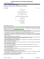
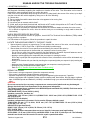
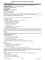
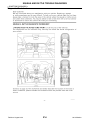
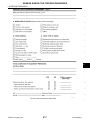
BODY INTERIOR
SECTION
IP
INSTRUMENT PANEL
A
B
C
D
E
CONTENTS
SYMPTOM DIAGNOSIS ............................... 2
SQUEAK AND RATTLE TROUBLE DIAGNOSES ................................................................ 2
Work Flow ................................................................. 2
Generic Squeak and Rattle Troubleshooting ............ 4
Diagnostic Worksheet ............................................... 6
STEERING COLUMN COVERS ....................... 13
Removal and Installation .........................................13
CENTER CONSOLE ASSEMBLY .................... 14
Exploded View .........................................................14
Removal and Installation .........................................14
CLUSTER LID A ............................................... 16
PRECAUTION ............................................... 8
Removal and Installation .........................................16
PRECAUTIONS ................................................... 8
CLUSTER LID C ............................................... 17
Precaution for Supplemental Restraint System
(SRS) "AIR BAG" and "SEAT BELT PRE-TENSIONER" ................................................................... 8
Precaution for Work .................................................. 8
CLUSTER LID D ............................................... 18
PREPARATION ............................................ 9
PREPARATION ................................................... 9
Special Service Tool ................................................. 9
Commercial Service Tools ....................................... 9
REMOVAL AND INSTALLATION ............... 10
INSTRUMENT PANEL ASSEMBLY ..................10
F
Removal and Installation .........................................17
Removal and Installation .........................................18
G
H
I
IP
INSTRUMENT LOWER PANEL LH .................. 19
Removal and Installation .........................................19
K
GLOVE BOX ASSEMBLY ................................ 20
Removal and Installation .........................................20
UNIT DISASSEMBLY AND ASSEMBLY ... 21
CENTER CONSOLE ASSEMBLY .................... 21
Exploded View ........................................................ 10
Removal and Installation ......................................... 11
Exploded View .........................................................21
Disassembly and Assembly .....................................21
L
M
N
O
P
Revision: August 2012
IP-1
2013 Maxima
SQUEAK AND RATTLE TROUBLE DIAGNOSES
< SYMPTOM DIAGNOSIS >
SYMPTOM DIAGNOSIS
SQUEAK AND RATTLE TROUBLE DIAGNOSES
Work Flow
INFOID:0000000008637889
SBT842
CUSTOMER INTERVIEW
Interview the customer if possible, to determine the conditions that exist when the noise occurs. Use the Diagnostic Worksheet during the interview to document the facts and conditions when the noise occurs and any
customer's comments; refer to IP-6, "Diagnostic Worksheet". This information is necessary to duplicate the
conditions that exist when the noise occurs.
• The customer may not be able to provide a detailed description or the location of the noise. Attempt to obtain
all the facts and conditions that exist when the noise occurs (or does not occur).
• If there is more than one noise in the vehicle, be sure to diagnose and repair the noise that the customer is
concerned about. This can be accomplished by test driving the vehicle with the customer.
• After identifying the type of noise, isolate the noise in terms of its characteristics. The noise characteristics
are provided so the customer, service adviser and technician are all speaking the same language when
defining the noise.
• Squeak —(Like tennis shoes on a clean floor)
Squeak characteristics include the light contact/fast movement/brought on by road conditions/hard surfaces
= higher pitch noise/softer surfaces = lower pitch noises/edge to surface = chirping.
• Creak—(Like walking on an old wooden floor)
Creak characteristics include firm contact/slow movement/twisting with a rotational movement/pitch dependent on materials/often brought on by activity.
• Rattle—(Like shaking a baby rattle)
Rattle characteristics include the fast repeated contact/vibration or similar movement/loose parts/missing
clip or fastener/incorrect clearance.
• Knock —(Like a knock on a door)
Knock characteristics include hollow sounding/sometimes repeating/often brought on by driver action.
• Tick—(Like a clock second hand)
Tick characteristics include gentle contacting of light materials/loose components/can be caused by driver
action or road conditions.
• Thump—(Heavy, muffled knock noise)
Thump characteristics include softer knock/dead sound often brought on by activity.
• Buzz—(Like a bumble bee)
Buzz characteristics include high frequency rattle/firm contact.
• Often the degree of acceptable noise level will vary depending upon the person. A noise that you may judge
as acceptable may be very irritating to the customer.
• Weather conditions, especially humidity and temperature, may have a great effect on noise level.
DUPLICATE THE NOISE AND TEST DRIVE
Revision: August 2012
IP-2
2013 Maxima
SQUEAK AND RATTLE TROUBLE DIAGNOSES
< SYMPTOM DIAGNOSIS >
If possible, drive the vehicle with the customer until the noise is duplicated. Note any additional information on
the Diagnostic Worksheet regarding the conditions or location of the noise. This information can be used to
duplicate the same conditions when you confirm the repair.
If the noise can be duplicated easily during the test drive, to help identify the source of the noise, try to duplicate the noise with the vehicle stopped by doing one or all of the following:
1) Close a door.
2) Tap or push/pull around the area where the noise appears to be coming from.
3) Rev the engine.
4) Use a floor jack to recreate vehicle “twist”.
5) At idle, apply engine load (electrical load, half-clutch on M/T model, drive position on CVT and A/T models).
6) Raise the vehicle on a hoist and hit a tire with a rubber hammer.
• Drive the vehicle and attempt to duplicate the conditions the customer states exist when the noise occurs.
• If it is difficult to duplicate the noise, drive the vehicle slowly on an undulating or rough road to stress the
vehicle body.
CHECK RELATED SERVICE BULLETINS
After verifying the customer concern or symptom, check ASIST for Technical Service Bulletins (TSBs) related
to that concern or symptom.
If a TSB relates to the symptom, follow the procedure to repair the noise.
LOCATE THE NOISE AND IDENTIFY THE ROOT CAUSE
1.
2.
A
B
C
D
E
F
Narrow down the noise to a general area. To help pinpoint the source of the noise, use a listening tool
(Chassis Ear: J-39570, Engine Ear: J-39565 and mechanic's stethoscope).
G
Narrow down the noise to a more specific area and identify the cause of the noise by:
• removing the components in the area that you suspect the noise is coming from.
Do not use too much force when removing clips and fasteners, otherwise clips and fasteners can be H
broken or lost during the repair, resulting in the creation of new noise.
• tapping or pushing/pulling the component that you suspect is causing the noise.
Do not tap or push/pull the component with excessive force, otherwise the noise will be eliminated only
I
temporarily.
• feeling for a vibration with your hand by touching the component(s) that you suspect is (are) causing the
noise.
• placing a piece of paper between components that you suspect are causing the noise.
IP
• looking for loose components and contact marks.
Refer to INT-8, "Generic Squeak and Rattle Troubleshooting".
REPAIR THE CAUSE
•
•
-
If the cause is a loose component, tighten the component securely.
If the cause is insufficient clearance between components:
separate components by repositioning or loosening and retightening the component, if possible.
insulate components with a suitable insulator such as urethane pads, foam blocks, felt cloth tape or urethane
tape. A NISSAN Squeak and Rattle Kit (J-43980) is available through your authorized NISSAN Parts Department.
CAUTION:
Do not use excessive force as many components are constructed of plastic and may be damaged.
Always check with the Parts Department for the latest parts information.
The following materials are contained in the NISSAN Squeak and Rattle Kit (J-43980). Each item can be
ordered separately as needed.
URETHANE PADS [1.5 mm (0.059 in) thick]
Insulates connectors, harness, etc.
76268-9E005: 100×135 mm (3.94×5.31 in)/76884-71L01: 60×85 mm (2.36×3.35 in)/76884-71L02: 15×25
mm (0.59×0.98 in)
INSULATOR (Foam blocks)
Insulates components from contact. Can be used to fill space behind a panel.
73982-9E000: 45 mm (1.77 in) thick, 50×50 mm (1.97×1.97 in)/73982-50Y00: 10 mm (0.39 in) thick,
50×50 mm (1.97×1.97 in)
INSULATOR (Light foam block)
80845-71L00: 30 mm (1.18 in) thick, 30×50 mm (1.18×1.97 in)
FELT CLOTH TAPE
Used to insulate where movement does not occur. Ideal for instrument panel applications.
68370-4B000: 15×25 mm (0.59×0.98 in) pad/68239-13E00: 5 mm (0.20 in) wide tape roll. The following
materials not found in the kit can also be used to repair squeaks and rattles.
Revision: August 2012
IP-3
2013 Maxima
K
L
M
N
O
P
SQUEAK AND RATTLE TROUBLE DIAGNOSES
< SYMPTOM DIAGNOSIS >
UHMW (TEFLON) TAPE
Insulates where slight movement is present. Ideal for instrument panel applications.
SILICONE GREASE
Used instead of UHMW tape that will be visible or not fit.
Note: Will only last a few months.
SILICONE SPRAY
Use when grease cannot be applied.
DUCT TAPE
Use to eliminate movement.
CONFIRM THE REPAIR
Confirm that the cause of a noise is repaired by test driving the vehicle. Operate the vehicle under the same
conditions as when the noise originally occurred. Refer to the notes on the Diagnostic Worksheet.
Generic Squeak and Rattle Troubleshooting
INFOID:0000000008860554
Refer to Table of Contents for specific component removal and installation information.
INSTRUMENT PANEL
Most incidents are caused by contact and movement between:
1. Cluster lid A and the instrument panel
2. Acrylic lens and combination meter housing
3. Instrument panel to front pillar finisher
4. Instrument panel to windshield
5. Instrument panel pins
6. Wiring harnesses behind the combination meter
7. A/C defroster duct and duct joint
These incidents can usually be located by tapping or moving the components to duplicate the noise or by
pressing on the components while driving to stop the noise. Most of these incidents can be repaired by applying felt cloth tape or silicone spray (in hard to reach areas). Urethane pads can be used to insulate wiring harness.
CAUTION:
Do not use silicone spray to isolate a squeak or rattle. If you saturate the area with silicone, you will
not be able to recheck the repair.
CENTER CONSOLE
Components to pay attention to include:
1. Shift selector assembly cover to finisher
2. A/C control unit and cluster lid C
3. Wiring harnesses behind audio and A/C control unit
The instrument panel repair and isolation procedures also apply to the center console.
DOORS
Pay attention to the:
1. Finisher and inner panel making a slapping noise
2. Inside handle escutcheon to door finisher
3. Wiring harnesses tapping
4. Door striker out of alignment causing a popping noise on starts and stops
Tapping or moving the components or pressing on them while driving to duplicate the conditions can isolate
many of these incidents. You can usually insulate the areas with felt cloth tape or insulator foam blocks from
the NISSAN Squeak and Rattle Kit (J-43980) to repair the noise.
TRUNK
Trunk noises are often caused by a loose jack or loose items put into the trunk by the owner.
In addition look for:
1. Trunk lid bumpers out of adjustment
2. Trunk lid striker out of adjustment
3. The trunk lid torsion bars knocking together
Revision: August 2012
IP-4
2013 Maxima
SQUEAK AND RATTLE TROUBLE DIAGNOSES
< SYMPTOM DIAGNOSIS >
4. A loose license plate or bracket
Most of these incidents can be repaired by adjusting, securing or insulating the item(s) or component(s) causing the noise.
SUNROOF/HEADLINING
Noises in the sunroof/headlining area can often be traced to one of the following:
1. Sunroof lid, rail, linkage or seals making a rattle or light knocking noise
2. Sun visor shaft shaking in the holder
3. Front or rear windshield touching headlining and squeaking
Again, pressing on the components to stop the noise while duplicating the conditions can isolate most of these
incidents. Repairs usually consist of insulating with felt cloth tape.
A
B
C
D
OVERHEAD CONSOLE (FRONT AND REAR)
Overhead console noises are often caused by the console panel clips not being engaged correctly. Most of
these incidents are repaired by pushing up on the console at the clip locations until the clips engage.
In addition look for:
1. Loose harness or harness connectors.
2. Front console map/reading lamp lens loose.
3. Loose screws at console attachment points.
E
F
SEATS
When isolating seat noise it's important to note the position the seat is in and the load placed on the seat when G
the noise is present. These conditions should be duplicated when verifying and isolating the cause of the
noise.
Cause of seat noise include:
H
1. Headrest rods and holder
2. A squeak between the seat pad cushion and frame
I
3. The rear seatback lock and bracket
These noises can be isolated by moving or pressing on the suspected components while duplicating the conditions under which the noise occurs. Most of these incidents can be repaired by repositioning the component
IP
or applying urethane tape to the contact area.
UNDERHOOD
Some interior noise may be caused by components under the hood or on the engine wall. The noise is then
transmitted into the passenger compartment.
Causes of transmitted underhood noise include:
1. Any component installed to the engine wall
2. Components that pass through the engine wall
3. Engine wall mounts and connectors
4. Loose radiator installation pins
5. Hood bumpers out of adjustment
6. Hood striker out of adjustment
These noises can be difficult to isolate since they cannot be reached from the interior of the vehicle. The best
method is to secure, move or insulate one component at a time and test drive the vehicle. Also, engine rpm or
load can be changed to isolate the noise. Repairs can usually be made by moving, adjusting, securing, or
insulating the component causing the noise.
K
L
M
N
O
P
Revision: August 2012
IP-5
2013 Maxima
SQUEAK AND RATTLE TROUBLE DIAGNOSES
< SYMPTOM DIAGNOSIS >
Diagnostic Worksheet
INFOID:0000000008637891
LAIA0072E
Revision: August 2012
IP-6
2013 Maxima
SQUEAK AND RATTLE TROUBLE DIAGNOSES
< SYMPTOM DIAGNOSIS >
A
B
C
D
E
F
G
H
I
IP
K
L
M
N
O
LAIA0071E
P
Revision: August 2012
IP-7
2013 Maxima
PRECAUTIONS
< PRECAUTION >
PRECAUTION
PRECAUTIONS
Precaution for Supplemental Restraint System (SRS) "AIR BAG" and "SEAT BELT
PRE-TENSIONER"
INFOID:0000000008637892
The Supplemental Restraint System such as “AIR BAG” and “SEAT BELT PRE-TENSIONER”, used along
with a front seat belt, helps to reduce the risk or severity of injury to the driver and front passenger for certain
types of collision. This system includes seat belt switch inputs and dual stage front air bag modules. The SRS
system uses the seat belt switches to determine the front air bag deployment, and may only deploy one front
air bag, depending on the severity of a collision and whether the front occupants are belted or unbelted.
Information necessary to service the system safely is included in the SR and SB section of this Service Manual.
WARNING:
• To avoid rendering the SRS inoperative, which could increase the risk of personal injury or death in
the event of a collision which would result in air bag inflation, all maintenance must be performed by
an authorized NISSAN/INFINITI dealer.
• Improper maintenance, including incorrect removal and installation of the SRS, can lead to personal
injury caused by unintentional activation of the system. For removal of Spiral Cable and Air Bag
Module, see the SR section.
• Do not use electrical test equipment on any circuit related to the SRS unless instructed to in this
Service Manual. SRS wiring harnesses can be identified by yellow and/or orange harnesses or harness connectors.
PRECAUTIONS WHEN USING POWER TOOLS (AIR OR ELECTRIC) AND HAMMERS
WARNING:
• When working near the Airbag Diagnosis Sensor Unit or other Airbag System sensors with the Ignition ON or engine running, DO NOT use air or electric power tools or strike near the sensor(s) with a
hammer. Heavy vibration could activate the sensor(s) and deploy the air bag(s), possibly causing
serious injury.
• When using air or electric power tools or hammers, always switch the Ignition OFF, disconnect the
battery, and wait at least 3 minutes before performing any service.
Precaution for Work
INFOID:0000000008637893
• When removing or disassembling each component, be careful not to damage or deform it. If a component
may be subject to interference, be sure to protect it with a shop cloth.
• When removing (disengaging) components with a screwdriver or similar tool, be sure to wrap the component
with a shop cloth or vinyl tape to protect it.
• Protect the removed parts with a shop cloth and prevent them from being dropped.
• Replace a deformed or damaged clip.
• If a part is specified as a non-reusable part, always replace it with new one.
• Be sure to tighten bolts and nuts securely to the specified torque.
• After installation is complete, be sure to check that each part works properly.
• Follow the steps below to clean components.
- Water soluble dirt: Dip a soft cloth into lukewarm water, and wring the water out of the cloth to wipe the dirty
area.
Then rub with a soft and dry cloth.
- Oily dirt: Dip a soft cloth into lukewarm water with mild detergent (concentration: within 2 to 3%), and wipe
the dirty area.
Then dip a cloth into fresh water, and wring the water out of the cloth to wipe the detergent off. Then rub with
a soft and dry cloth.
• Do not use organic solvent such as thinner, benzene, alcohol, or gasoline.
• For genuine leather seats, use a genuine leather seat cleaner.
Revision: August 2012
IP-8
2013 Maxima
PREPARATION
< PREPARATION >
PREPARATION
A
PREPARATION
Special Service Tool
INFOID:0000000008637894
B
The actual shapes of Kent-Moore tools may differ from those of special service tools illustrated here.
Tool number
(Kent-Moore No.)
Tool name
Description
C
—
(J-39570)
Chassis ear
Locating the noise
D
E
F
SIIA0993E
—
(J-43980)
NISSAN Squeak and Rattle
Kit
Repairing the cause of noise
G
H
SIIA0994E
—
(J-46534)
Trim tool set
Removing trim components
I
IP
AWJIA0483ZZ
K
Commercial Service Tools
INFOID:0000000008637895
Tool name
Description
Engine ear
Locating the noise
L
M
N
SIIA0995E
Power tool
Loosening nuts, screws and bolts
O
P
PIIB1407E
Revision: August 2012
IP-9
2013 Maxima
INSTRUMENT PANEL ASSEMBLY
< REMOVAL AND INSTALLATION >
REMOVAL AND INSTALLATION
INSTRUMENT PANEL ASSEMBLY
Exploded View
INFOID:0000000008637896
ALJIA0328ZZ
Revision: August 2012
IP-10
2013 Maxima
INSTRUMENT PANEL ASSEMBLY
< REMOVAL AND INSTALLATION >
1.
Center speaker grille (if equipped)
2.
Tweeter speaker grille (LH)
3.
Front defroster grille (LH)
4.
Instrument panel
5.
Instrument side finisher (LH)
6.
Lower knee protector (LH)
7.
Instrument lower panel (LH)
8.
Fuse block cover
9.
Steering column lower cover (power
tilt)
11.
Steering column side cover (LH) (pow- 12. Steering column side cover (RH)
er tilt)
(power tilt)
10. Steering column screw finisher (LH)
(power tilt)
A
13. Steering column upper cover (power 14. Steering column screw cover finisher
tilt)
(RH) (power tilt)
15. Combination meter
16.
18. Steering column upper cover (manual tilt)
Multifunction switch (with color display) or A/C switch assembly (with
monochrome display)
17. Cluster lid D
B
C
D
19. Steering column lower cover (manual 20. Steering column screw finisher (LH)
tilt)
(manual tilt)
21. Steering column screw cover finisher
(RH) (manual tilt)
22. Cluster lid A
23. Cluster lid C (with color display)
24. Cluster lid C lower finisher (with
monochrome display)
25. Cluster lid C (with monochrome display)
26. Glove box assembly
27. Instrument side finisher (RH)
28. Tweeter speaker grille (RH)
29. Front defroster grille (RH)
E
F
Clip
Metal clip
Removal and Installation
INFOID:0000000008637897
CAUTION:
• Be careful not to scratch instrument panel pad and other parts.
• Before servicing, turn ignition switch OFF, disconnect both battery terminals and wait at least three
minutes.
2.
3.
H
I
REMOVAL
1.
G
Disconnect the negative and positive battery terminals, then wait at least three minutes. Refer to PG-67,
"Removal and Installation (Battery)".
IP
Remove the steering wheel. Refer to ST-17, "Removal and Installation".
Using a suitable tool, gently remove both instrument panel side
finishers (1).
K
L
M
ALJIA0335ZZ
4.
5.
6.
7.
8.
9.
10.
11.
12.
Remove the instrument lower panel (LH) (1). Refer to IP-19, "Removal and Installation".
Remove the steering column covers. Refer to IP-13, "Removal and Installation".
Remove cluster lid A. Refer to IP-16, "Removal and Installation".
Remove the combination meter. Refer to MWI-121, "Removal and Installation".
Remove the glove box assembly. Refer to IP-20, "Removal and Installation".
Remove the front passenger air bag module. Refer to SR-9, "Removal and Installation".
Remove cluster lid D. Refer to IP-18, "Removal and Installation".
Remove cluster lid C. Refer to IP-17, "Removal and Installation".
Remove the display screen. Refer to AV-72, "Removal and Installation" (BASE AUDIO), AV-170,
"Removal and Installation" (BOSE W/MONOCHROME DISPLAY), AV-337, "Removal and Installation"
(BOSE W/COLOR DISPLAY) or AV-508, "Removal and Installation" (BOSE W/COLOR DISPLAY W/
NAVI).
13. Remove the front pillar finishers (LH/RH). Refer to INT-24, "Removal and Installation".
Revision: August 2012
IP-11
2013 Maxima
N
O
P
INSTRUMENT PANEL ASSEMBLY
< REMOVAL AND INSTALLATION >
14. Remove the center console side finishers (LH/RH). Refer to IP-14, "Exploded View".
15. Remove both tweeter speaker grilles and disconnect the harness connectors.
16. Remove the tweeter speakers (LH/RH). Refer to AV-73, "Removal and Installation" (BASE AUDIO), AV173, "Removal and Installation" (BOSE W/MONOCHROME DISPLAY), AV-343, "Removal and Installation" (BOSE W/COLOR DISPLAY) or AV-514, "Removal and Installation" (BOSE W/COLOR DISPLAY W/
NAVI).
17. Remove the center speaker (if equipped). Refer to AV-172, "Removal and Installation" BOSE W/MONOCHROME DISPLAY), AV-342, "Removal and Installation" (BOSE W/COLOR DISPLAY) or AV-513,
"Removal and Installation" (BOSE W/COLOR DISPLAY W/NAVI).
18. Remove the remaining instrument panel screws (A).
ALJIA0342ZZ
19. Disconnect the audio harness connectors located near the RH A-pillar.
20. Lift the instrument panel high enough in order to disconnect the harness clip attached to the air duct, and
all the necessary harness connectors, then remove the instrument panel.
INSTALLATION
Installation is in the reverse order of removal.
• If replacing the instrument panel, transfer all the necessary parts to the new instrument panel.
Revision: August 2012
IP-12
2013 Maxima
STEERING COLUMN COVERS
< REMOVAL AND INSTALLATION >
STEERING COLUMN COVERS
A
Removal and Installation
INFOID:0000000008637898
MANUAL TILT
B
Removal
1.
2.
3.
Remove the steering column cover screw finishers (1) and then
remove the screws.
Remove the steering column upper cover (2).
Remove the steering column lower cover screw and then
remove the steering column lower cover (3).
C
D
E
ALJIA0456ZZ
F
Installation
Installation is in the reverse order of removal.
G
POWER TILT
Removal
1.
2.
3.
4.
5.
Remove the steering column screw cover finishers (1) and then
remove the screws.
Remove the steering column upper cover (2).
Remove the steering column side cover (LH) (4).
Remove the steering column side cover (RH) (3).
Remove the screws and then remove the steering column lower
cover (5).
H
I
IP
ALJIA0455ZZ
K
Installation
Installation is in the reverse order of removal.
L
M
N
O
P
Revision: August 2012
IP-13
2013 Maxima
CENTER CONSOLE ASSEMBLY
< REMOVAL AND INSTALLATION >
CENTER CONSOLE ASSEMBLY
Exploded View
INFOID:0000000008637899
AWJIA0542ZZ
1.
Center console side finisher (LH)
2.
Center console finisher
3.
CVT finisher
4.
Center console storage bin
5.
Center console screw cover (LH)
6.
Center console rear finisher
7.
Center console screw cover (RH)
8.
Center console
9.
Center console lid assembly
10. Cup holder
Clip
11. Center console side finisher (RH)
Metal clip
Vehicle front
Pawl
Removal and Installation
INFOID:0000000008637900
REMOVAL
CAUTION:
Be careful not to scratch center console finishers and other parts.
1. Remove the center console side finishers (LH/RH).
2. Disconnect the center console harness connectors (A).
ALJIA0344ZZ
Revision: August 2012
IP-14
2013 Maxima
CENTER CONSOLE ASSEMBLY
< REMOVAL AND INSTALLATION >
3.
4.
5.
Remove the CVT shift selector handle. Refer to TM-168, "Removal and Installation".
Remove the CVT finisher, using a suitable tool and while disconnecting necessary connectors.
Remove the center console screws (A).
A
B
C
D
ALJIA0345ZZ
6.
7.
8.
E
Position the front seats forward (LH/RH).
Remove the center console screw covers (LH/RH) and the rear
center console screw (A) from each side of the rear of the center
console assembly (1).
Remove the center console assembly (1).
F
G
H
ALJIA0346ZZ
INSTALLATION
I
Installation is in the reverse order of removal.
IP
K
L
M
N
O
P
Revision: August 2012
IP-15
2013 Maxima
CLUSTER LID A
< REMOVAL AND INSTALLATION >
CLUSTER LID A
Removal and Installation
INFOID:0000000008637901
REMOVAL
1.
Using a suitable tool, gently remove the instrument side finisher
(LH) (1).
ALJIA0335ZZ
2.
a.
b.
c.
Remove the instrument lower panel (LH) (1).
Open the fuse block cover and remove the instrument lower
panel screw (A).
Disconnect the harness connectors and aspirator hose.
Remove the instrument lower panel (LH) (1).
ALJIA0336ZZ
3.
Remove cluster lid A screws, release the metal clips, and remove cluster lid A.
INSTALLATION
Installation is in the reverse order of removal.
Revision: August 2012
IP-16
2013 Maxima
CLUSTER LID C
< REMOVAL AND INSTALLATION >
CLUSTER LID C
A
Removal and Installation
INFOID:0000000008637902
CLUSTER LID C
B
NOTE:
The cluster lid C lower finisher is only used in vehicles equipped with monochrome display unit.
C
Removal - With Monochrome Display
1.
2.
Release the clips and pawls and remove cluster lid C lower finisher (1).
: Clip
: Pawl
Remove cluster lid C (base audio) with the base audio unit.
Refer to AV-70, "Removal and Installation" (BASE AUDIO) or
AV-168, "Removal and Installation" (BOSE W/MONOCHROME
DISPLAY).
D
E
F
ALNIA1152ZZ
Installation
Installation is in the reverse order of removal.
G
Removal - With Color Display
1.
2.
3.
H
Remove cluster lid D. Refer to IP-18, "Removal and Installation".
Remove the screws (A) and reposition cluster lid C (1) to access
the harness connectors.
Disconnect the harness connectors and the remove cluster lid C
(Bose audio) with the Bose audio unit. Refer to AV-334,
"Removal and Installation" (BOSE W/COLOR DISPLAY) or AV508, "Removal and Installation" (BOSE W/COLOR DISPLAY W/
NAVI).
I
IP
K
ALJIA0340ZZ
Installation
Installation is in the reverse order of removal.
L
M
N
O
P
Revision: August 2012
IP-17
2013 Maxima
CLUSTER LID D
< REMOVAL AND INSTALLATION >
CLUSTER LID D
Removal and Installation
INFOID:0000000008637903
REMOVAL
1.
2.
Release the metal clips using a suitable tool, then position cluster lid D (1) aside.
Disconnect the harness connectors, then remove cluster lid D
(1).
: Metal clip
AWJIA0548ZZ
INSTALLATION
Installation is in the reverse order of removal.
Revision: August 2012
IP-18
2013 Maxima
INSTRUMENT LOWER PANEL LH
< REMOVAL AND INSTALLATION >
INSTRUMENT LOWER PANEL LH
A
Removal and Installation
INFOID:0000000008637904
REMOVAL
1.
B
Using a suitable tool, gently remove the instrument side finisher
(LH) (1).
C
D
E
ALJIA0335ZZ
2.
a.
b.
c.
Remove the instrument lower panel (LH) (1).
Open the fuse block cover and remove the instrument lower
panel screw (A).
Disconnect the harness connectors and aspirator hose.
Remove the instrument lower panel (LH) (1).
F
G
H
ALJIA0336ZZ
I
INSTALLATION
Installation is in the reverse order of removal.
IP
K
L
M
N
O
P
Revision: August 2012
IP-19
2013 Maxima
GLOVE BOX ASSEMBLY
< REMOVAL AND INSTALLATION >
GLOVE BOX ASSEMBLY
Removal and Installation
INFOID:0000000008637905
REMOVAL
1.
2.
Using a suitable tool, gently remove the instrument panel side finisher (RH).
Open the glove box door and then remove the glove box assembly screws (A).
ALJIA0337ZZ
3.
4.
Remove the glove box assembly lower screws (A).
Disconnect the harness connectors, then remove the glove box
assembly (1).
ALJIA0338ZZ
INSTALLATION
Installation is in the reverse order of removal.
Revision: August 2012
IP-20
2013 Maxima
CENTER CONSOLE ASSEMBLY
< UNIT DISASSEMBLY AND ASSEMBLY >
UNIT DISASSEMBLY AND ASSEMBLY
A
CENTER CONSOLE ASSEMBLY
Exploded View
INFOID:0000000008637906
B
C
D
E
F
G
H
I
IP
AWJIA0542ZZ
1.
Center console side finisher (LH)
2.
Center console finisher
3.
CVT finisher
4.
Center console storage bin
5.
Center console screw cover (LH)
6.
Center console rear finisher
7.
Center console screw cover (RH)
8.
Center console
9.
Center console lid assembly
10. Cup holder
Clip
11. Center console side finisher (RH)
Metal clip
L
Vehicle front
M
Pawl
Disassembly and Assembly
K
INFOID:0000000008637907
N
DISASSEMBLY
1.
2.
3.
4.
5.
6.
7.
Remove the center console assembly. Refer to IP-11, "Removal and Installation".
Remove the power sockets. Refer to PWO-7, "Removal and Installation".
Remove the center console finisher switches (if equipped), then detach the harness clips and remove the
center console harness.
Remove the cup holder screws and then remove the cup holder assembly.
Remove the center console storage bin screws and then remove the center console storage bin.
Remove the center console rear finisher.
Remove the center console lid assembly screws and remove the center console lid assembly.
ASSEMBLY
Assembly is in the reverse order of disassembly.
Revision: August 2012
IP-21
2013 Maxima
O
P