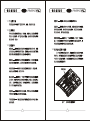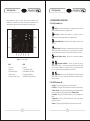
1
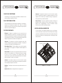
Operation Manual
AvantAC Classic Bus Air Conditioning Units
Carrier Transicold China
1235
201821
86-21-59166868
86-21-59165013
Headquarter: No.1235 Ye Cheng Rd. Jiading District, Shanghai, 201821, China Tel: 86-21-59166868 Fax: 86-21-59165013
60
200434
86-21-65923817
86-21-65923827
Service Centre: No.60 Guang Yue Rd. Shanghai, 200434, China Tel: 86-21-65923817 Fax: 86-21-65923827
77-66892-00 Rev. -
CSDD
................................................................................................... 2
................................................................................................... 3
/
............................................................................... 4
1.1
........................................................................ 4
1.2
........................................................................... 4
1.3
........................................................................... 4
....................................................... 5
1.4
........................................................................................... 6
........................................................... 7
2.1
2.1.1
/
................................................................. 7
2.1.2
.............................................. 7
2.1.3
.......................................... 8
2.2
........................................................................ 8
2.3
............................................................................ 8
2.3.1
...................................................................... 8
2.3.2
.............................................. 9
2.3.3
.................................................................. 9
2.3.4
.......................................................................... 10
2.3.5
.................................................................. 10
2.3.6
..................................................................10
2.3.7
..................................................................11
..................................................................11
2.3.8
...........................................................................................12
............................................................................12
3.1
3.2
/
................................................................12
........................................................................13
3.3
...................................................................................................14
1
2
3
1.1
1.2
1.3
1.3
1.4
/
1-1
4
5
2.1
2.1.1
1
6
2
5
/
2.1.2
+
7
3
8
4
9
1
1
10
2-1
/
1
6
+
7
2
3
8
/
4
9
5
10
1-5
20% 40% 60% 80% 100%
+
10
10
3
6
7
2.1.3
2.3.2
a.
b.
(
)-7
c.
(
d.
)-8
18
/
(
2
)-9
e.
(
f.
(
(
)
) - 10
2.3.3
)-7 8
2.2
0.5
10-15
a.
b.
0.5
c.
d.
2
2.3
2.3.1
8
9
28
2.3.4
2.3.7
6
20%
40%
60%
80%
100%
2.3.8
2.3.5
3
2
2.3.6
i 22
10
o 19
i --
10
o --
11
3.1
3.3
a.
b.
3.2
c.
d.
e.
12
13
A
P
3
5
B
Q
12
9
C
OPERATION
MANUAL
S
8
4
D
X
4
12
4
G
8
4
5
H
Y
5
4
J
5
4
6
8
Z
4
5
2
/
K
12
3, 4
4
L
4
14
BUS AIR CONDITIONING
UNITS
AvantAC Classic
with CSDD Controller
Contents
Introduction .............................................................................................................. 18
Safety ......................................................................................................................... 19
Unit/System Information ........................................................................................ 20
1.1 What is Air Conditioning .............................................................................. 20
1.2 Air Conditioning System .............................................................................. 20
1.3 System Componebts ................................................................................... 20
1.4 Model And Serial Number Tags .................................................................. 21
Unit Operation .......................................................................................................... 22
2.1 Driver Display Functions .............................................................................. 23
2.1.1 Key Functions, Engine On .................................................................. 23
2.1.2 Led Functions, Engine On .................................................................. 23
2.2 Pre-trip Inspection ........................................................................................ 24
2.3 Operating Instructions ................................................................................. 24
2.3.1 Display .................................................................................................. 24
2.3.2 Starting And Interior Temperature Control ........................................ 24
2.3.3 Automatic Climate Control .................................................................. 24
2.3.4 Vent ...................................................................................................... 25
2.3.5 Manual Reheat ................................................................................... 25
2.3.6 Temperature Indication ........................................................................ 26
2.3.7 Dry Heat Mode .................................................................................... 26
2.3.8 Eco Mode ............................................................................................. 26
System Maintenance .............................................................................................. 27
3.1 Warranty/service ........................................................................................... 27
3.2 Maintenance Schedule ................................................................................ 28
Index ........................................................................................................................... 29
17
Safety
Introduction
AvantAC Classic Operation Manual
This guide has been prepared for the operator of Carrier Transport Air
Conditioning systems. It contains basic instructions for the daily operation of the
air conditioning system as well as safety information, and other information that
will help you to maintain a comfort level for your self and your passengers. Please
take the time to read the information contained in this booklet and refer to it
whenever you have a question about the operation of your Carrier Transport Air
Conditioning system.
More comprehensive information can be found in the AvantAC Operation and
Service Manual. This manual can be obtained from your Carrier Transport A/C
dealer.
Your air conditioning system has been engineered to provide long, trouble-free
performance when it is properly operated and maintained. A comprehensive
maintenance program will help to insure that the unit continues to operate reliably.
Such a maintenance program will also help to control operating costs, increase
the unit's working life, and improve performance.
Some Vehicles may require information from manuals supplied by the vehicle
manufacturer or other special equipment suppliers. We urge you to review all
these publications carefully. This will help you enjoy safe and trouble-free
operation of your vehicle. When having your unit serviced, be sure to specify
genuine Carrier Transicold replacement parts for the highest quality and best
reliability.
Your Carrier Transport Air Conditioning system has been designed with the safety
of the operator in mind. During normal operation, all moving parts are fully
enclosed to help prevent injury. During all pre-trip inspections, daily inspections,
and problem troubleshooting, you may be exposed to moving parts; please stay
clear of all moving parts when the unit is in operation.
Beware of unannounced starting of the unit. The unit may
cycle the fans and operating compressor unexpectedly as
control requirements dictate. Turn system off and
disconnect battery power.
REFRIGERANT
The refrigerant contained in the air conditioning system can cause frostbite,
severe burns, or blindness when in direct contact with the skin or eyes. For this
reason, and because of legislation regarding the handling of refrigerants during
system service, we recommend that, whenever your unit requires service of the
refrigeration system, you contact your nearest Carrier Transport Air Conditioning
authorized dealer for service.
At Carrier Transport Air Conditioning, we are continually working to improve the
products that we build for our customers. As a result, specifications may change
without notice.
18
19
Unit/System Information
Unit/System Information
1.1 WHAT IS AIR CONDITIONING
Air Conditioning is the cooling, heating, dehumidification, and filtration of the air
within the passenger compartment of a vehicle.
1.2 AIR CONDITIONING SYSTEM
An Air Conditioning System normally includes an evaporator(s), a condenser(s), a
compressor and interconnecting refrigerant hoses, fittings, and electrical
harnesses and controls. A listing of the system components, along with specific
data for each, is provided in Paragraph 1.3.
1.3 SYSTEM COMPONENTS
Refrigerant - A refrigerant is a material that is used to move heat from the
passenger compartment to the outside air. It is a substance that gives up heat by
condensing at high temperature and pressures and absorbs heat by evaporating
at low temperatures and pressures. The heat transfer properties exhibited when
refrigerant changes state is the foundation of the refrigerant cycle.
Compressor - The compressor is a belt driven, high-pressure pump, which
circulates the refrigerant through the evaporator and condenser . The operation of
the compressor is controlled by the Electro-Magnetic clutch.
Evaporator - The evaporator is located on the roof of the vehicle. Its primary
function is to transfer heat contained in the passenger compartment air, into the
refrigerant, which is circulated by the compressor, through the evaporator coil.
During this process the air is also dehumidified.
Return Air Sensor - The system is supplied with a thermistor. This device is a
temperature sensitive component which when activated, signals the ElectroMagnetic Clutch to engage/disengage. The return air thermistor is normally
located in the return air flow of the evaporator assembly.
1.4 MODEL AND SERIAL NUMBER TAGS
In order to identify the air conditioning components you have, you will need to
know the model number and serial number. All Carrier Transport Air Conditioning
systems have a model/serial number tag located on the assembly. Knowing these
locations and the information on the data tags will aid you in identifying the correct
service procedures.
Equipment Identification
Electro-Magnetic Clutch - The Electro--Magnetic clutch controls the operation
of the compressor. When engaged, the compressor circulates refrigerant and
provides cooling.
Pressure Switch - The systems use a high pressure switch wired to control the
power circuit of the compressor clutch. If the pressure switch opens, interrupting
the circuit to the clutch, the operation of the compressor will stop. When
conditions return to normal the switch will automatically reset and the compressor
will resume operating. The switch is non--adjustable.
Condenser - The condenser is located on the roof of the vehicle. Its primary
function is to reject heat, which was transferred to the refrigerant by the evaporator
from the passenger compartment of the vehicle.
Filter/Dryer - The filter/dryer removes moisture and particulate matter from the
refrigerant.
Figure 1-1 I.D. Tag Location
Expansion Valve - Meters the refrigerant flow into the evaporator coil.
20
21
Unit Operation
Unit Operation
Before attempting to operate the system, power must be available from the
vehicle battery. If the engine is not running, start the engine. Most systems will not
operate unless a signal is received at the controller from the vehicle ignition.
2.1 DRIVER DISPLAY FUNCTIONS
2.1.1 Key Functions, On
Plus Key - Increases vehicle setpoint by 1 degree per stroke or increases
manual blower speed, depending on displayed mode.
1
6
Minus Key - Decreases vehicle setpoint by 1 degree per stroke or
decreases manual blower speed, depending on displayed mode.
Recirulating/Fresh Air - Switches from Recirculating Air to Fresh Air and
vice versa.
2
5
7
3
8
4
9
10
Figure 2-1 Drivers Display
KEYS
1. Plus Key
2. Minus Key
3. Recirculate/Fresh Air
4. Blower Control
5. Automatic Climate Control
LEDS
6. Display
7. Fresh Air Open (Green)
8. Manual Blower 'ON' (Green)
9. Cooling/Heating (Green)
10.Malfunction Cooling Unit (Red)
Blower Control - Switches the evaporator blower motors from automatic
speed control (based on contoller inputs) to manual control where the operator
may select blower speed based on the number of times the Plus Key is stroked.
Automatic Climate Control - Switches on the automatic temperature
control.
+
Temperature Indication - Use two keys, Minus Key and the
Recirulating/Fresh Air Key - If both keys are pressed simultaneously the display
shows the inside temperature for 10 seconds, if both keys are pressed a second
time, the outside temperature will be displayed for 10 seconds.
+
Reheat - Use two keys, Recirulating/Fresh Air Key plus Automatic
Climate Control - If both keys are pressed simultaneously the system will run in
reheat for 3 minutes.
2.1.2 LED Functions, On
a. Display - The standard indication is the set point temperarture.
b. Fresh Air - (7)This green LED will illuminate when the fresh air damper is open.
c. Blower Control - (8)This green LED will illuminate when the evaporator blower
motors are controlled manually as described in 2.1.1 'Blower Control'.
d. Cool/Heat - (9)This green LED will illuminate when the unit is operating in Auto
Mode.
e. Malfunction - (10)This red LED will illuminate when a low or high pressure
safety switch activates.
f. Reheat - (7-8) Both green LED's will flash when the reheat function is active.
22
23
Unit Operation
Unit Operation
2.2 PRE-TRIP INSPECTION
After starting system, allow system to stabilize for ten to fifteen minutes and check
for the following:
a. Listen for abnormal noises in compressor or fan motors.
b. Check compressor oil level.
c. Check refrigerant charge.
d. Ensure that there are no alarms indicated.
2.3 OPERATING INSTRUCTIONS
Cooling: If system is not operating in ECO Mode (see Section2.3.8) and if the
vehicle interior temperature rises more than 0.5 above the setpoint temperature,
the control energizes the compressor clutch. If the vehicle interior temperature
reaches the set point, the compressor clutch is switched off. If the ambient
temperature sensor is in operational, cooling is not allowed whenever the ambient
temperature is below 2 .
Blower: If automatic blower control is selected, the evaporator blower speed will
vary in response to the relationship to the vehicle interior temperature and the
controller set point temperature.
2.3.4 Vent
When the engine is started, previously set functions of the control are reactivated.
The blowers may be switched to manual mode of operation by pressing the
2.3.1 Display
The display is dark when the unit is OFF. When the unit is ON the display shows
the interior setpoint temperature. When selecting individual functions, the display
shows the corresponding information for a short period of time.
2.3.2 Starting And Interior Temperature Control
If the engine is not running, start the engine.
Pressing the Automatic Climate Control key
The blowers cannot be switched OFF when Automatic Climate Control is ON.
When Automatic Climate Control is OFF, the blowers stop when the manual
blower control is turned to OFF.
2.3.5 Manual Reheat
- will start vehicle interior
temperature control. Press the Plus
- or Minus
- Keys to set the
required temperature. The temperature can be adjusted between 18 and 28 .
The cooling functions will be disabled if ambient air temperatures are below 2 .
2.3.3 Automatic Climate Control
After selecting the automatic climate control the unit will be governed in
relationship to the vehicle interior temperature and set point temperature.
Heating: If the vehicle interior temperature drops more than 0.5
below the
setpoint temperature, the control switches on the heating. If the vehicle interior
temperature reaches the set point, the heating is switched off.
24
Blower key
. Press the plus
or minus
keys to select one of 6
(20%, 40%, 60%, 80%, 100%, and OFF) different blower speeds.
The Reheat mode is used to lower the air humidity and to help defogging the
windshields. Press the Recirculating/Fresh Air Key
and the Automatic
Climate Control Key
at the same time to activate Reheat. Heating and
cooling will be energized for 3 minutes. In addition, the evaporator blowers will be
switched to maximum speed and the fresh air flap will be closed. At the end of the
of Reheat, the functions will return to previouly selected settings.
Reheat is disabled with ambient temperatures below 2
sensor fails.
25
or if the ambient air
Unit Operation
System Maintenance
2.3.6 Temperature Indication
Press the Recirculating/Fresh Air Key
and the Minus Key
at the same
Time to display the interior temperature (example ''i 22''). The display will return to
the original setting after 10 seconds.
a second
Be sure to observe warnings listed in the safety summary in
the front of this manual before performing maintenance on
the HVAC system.
If the Dry Heat mode is active, the compressor will operate when heating is called
for.
Read the entire procedure before beginning work. Park the
coach on a level surface, with parking brake applied. Turn
main electrical disconnect switch to the off position.
Pressing the Recirculating/Fresh Air Key
and the Minus Key
time will display the ambient temperature (example ''o 19'').
A sensor malfunction will display as ''i --'' or ''o --''.
2.3.7 Dry Heat Mode
Manual Reheat is disabled when Dry Heat is active.
An absent or defective ambient sensor disables Dry Heat.
Dry Heat is disabled if the Fresh Air Flap opens for any reason.
NOTE
To avoid damage to the earth's ozone layer, use a refrigerant recovery system
whenever removing refrigerant. When working with refrigerants you must comply
with all local government environmental laws.
2.3.8 ECO Mode
In ECO Mode the controller will allow the vehicle interior temperature to rise but at
a rate that maintains comfort levels.
When ambient temperature rises to the ECO Mode start point, the controller will
control the vehicle interior temperature in accordance with a set difference in
temperature between ambient temperature and vehicle interior temperature.
3.1 Warranty/Service
Thank you for choosing a Carrier Transport Air Conditioning system for your
vehicle. We want to assure you of our continuing interest in your pleasure and
satisfaction with your air conditioning system. Remember, if you have a question
or concern and need help, contact your nearest Transport Air Conditioning Dealer.
Manual re-setting of the set point temperature with the Plus or Minus keys is not
possible.
Manual Reheat is disabled if ECO mode is operational.
A defective or missing ambient sensor disables the ECO mode Function.
26
27
System Maintenance
Index
A
3.2 Maintenance Schedule
R
Air Conditioning System
SYSTEM
ON OFF
a. Daily Maintenance
OPERATION
Pre-trip inspection - after starting. (Refer to paragraph 2.2)
Check tension and condition of drive belts.
b. Weekly Maintenance
20
C
20
Safety
19
Compressor
20
Sensor - Return Air
21
Condenser
20
Serial Tag
21
Starting
24
Switch - Pressure
20
System Components
20
System Maintenance
27
Unit Information
20
Unit Operation
22
Valve - Expansion
20
Warranty/Service
27
Display
24
E
Evaporator
Check condenser, evaporator coils, return air filters
Check refrigerant hoses and compressor shaft seal for leaks
Filter/Dryer
Check wire harnesses for chafing and loose terminals
Check fan motor bearings
20
Introduction
18
V
Maintenance Schedule
28
W
Model Tag
21
M
Perform weekly inspection
Clean evaporator drain pans and hoses
U
I
Feel filter-drier for excessive temperature drop across drier
c. Monthly Maintenance and Inspection
21
F
(if equipped) and fresh air filters for cleanliness
O
What Is Air Conditioning 20
Operating Instructions
24
Pre - Trip Inspection
24
P
Check compressor mounting bolts for tightness
d. Semi-Annual Inspection and Maintenance
Check system pressures
Check refrigerant in sight glass
Check element in the the liquid line sight glass. (If equipped)
Inspect condenser fan blades
Open bus heater valves (In winter)
Close bus heater valves (In spring)
e. Annual Inspection and Maintenance
Inspect electrical panel and terminals. Clean if needed with a highgrade cleaner specifically formulated for this purpose.
Inspect Evaporator drain pan. (Clean if needed)
Check pressure switch operation
Check system roof mounting and sealing
28
19,20
Clutch - Electro - Magnetic
D
Perform daily inspection
Refrigerant
S
29