1
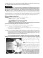
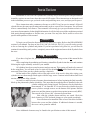
00
HOME OF
REAL WORLD POWER
TWIN CAM
INSTRUCTIONS
1
AXTELL SALES
1424 MAURY ST
DES MOINES, IOWA 50317
515.243.2518
[email protected]
1
Congratulations on making a wise investment in your bike’s future. Our Axtell Sales cylinder
kits have a proven track record for high performance, quality workmanship, and relentless dedication to
customer service. This instruction manual should facilitate the installation of the kit and have you back
on the road producing Real World Power.
SECTION 1
Axtell Sales Company Policy
SECTION 2
Things to Remember
SECTION 3
Machining
SECTION 4
Specifications
SECTION 5
Installation
SECTION 6
Before Riding
SECTION 7
Further Information
Please read instructions thoroughly before beginning your installation. If you still have questions
regarding your install after reading this manual, please contact our tech line at 1.515.243.6069
.axtellsales.com for product, service and
Also, make sure to check out our web site at www
www.axtellsales.com
news updates.
LAST REV. 06/04
2
22
Axtell Sales Company Policy
Disclaimer
All Axtell Sales products are intended for of
offf road use only
only..
The words Harley Davidson™, EVO™, XL™, Evolution™, Sportster™, Big Twin™, Twin
Cam™, Shovelhead™, and Panhead™ are used as a reference only and are not intended to imply that
these parts are manufactured or endorsed by Harley Davidson Motor Company.
It is the responsibility of the user to determine if any products sold by Axtell Sales are appropriate
for their desired application. The user will assume any and all legal and personal injury risk and liability,
and all other obligations, duties, and risks associated with the installation of these parts.
Limited Warranty
All of Axtell Sales, Inc. products are to be manufactured free from defects in material and
workmanship at the time of manufacture. It is the responsibility of the purchaser to inspect all goods
carefully before use. Any returns are to be made before the product is installed or modified in any way.
Credit, repair, or replacement of goods is predicated upon factory inspection. Axtell Sales Inc. is not
responsible for improper installation of or damage due to abuse (including competitive racing, dynoing,
etc.) or improper lubrication. (For warranty claims on items not manufactured by Axtell Sales please
refer to original manufacturer.)
Returns
Any merchandise that appears to be damaged in shipping must be reported immediately. Do not
send parts back. All returns or exchanges must be made before use and within 30 days of purchase. Call
or write for authorization before returning any merchandise. Returns must be shipped in original boxes
and accompanied by a copy of the original invoice. All return freight will be paid by the returnee.
Returns for any reason other than defective merchandise are subject to a 15% restocking fee.
There are no refunds on any custom order parts.
Payment Terms
A 50% deposit is required on all custom-made cylinder orders. We require advance wire transfer
payment on all foreign accounts. Payments may also be made using Visa, Master Card, Discover, or
American Express.
Shipping
All orders will be shipped United Parcel Service C.O.D. unless other arrangements have been
made in advance. A service charge of $5.00 will be added to all orders less than $25.00; this charge may
be waived for customers whose volume warrants occasional small orders without penalty. Any customer
1that refuses any order will be required to post a $25.00 shipping bond on their next order.
Prices
All listed catalog prices are suggested retail and are subject to change without notice.
22
3
Things to Remember
Instructions in this manual are intended to be used in conjunction with the service manual
corresponding to your bike. Don’t have one? Go to your local Harley dealership and get one. You’ll
wonder how you ever got along without it.
INSTALLING
PAR
ARTS
THINGS TO REMEMBER WHEN INST
ALLING ENGINE P
AR
TS
Work Clean
Nothing can damage your vital engine parts like dirt. Foreign debris (dirt, filings, etc.) in your
bike’s engine can cause premature failure by scratching your cylinder walls, piston skirts, and obstructing
vital oil passages, just to name a few. Make sure to work in a clean environment with clean tools. A
clean, well-built motor will last you for years.
Beware of any obstructions in your motor. Any sharp edges on your kit should be addressed.
Sharp edges can produce detonation in the combustion chamber or scuffing of the piston skirt. Both
lead to premature engine failure. When removing edges, use a good hand file, not an abrasive wheel.
Wheels imbed grit into the metal, drastically shortening your engine’s life.
Work Smart
Always use good judgment when installing our cylinder kits. A hastily built motor will not last
as long as one that is put together with care. A good, clear head is absolutely necessary during installation.
Make sure to double-, and maybe even triple-, check your work. You may be itchin’ to ride, but you
would sure wish you would have taken your time when your motor’s life is cut short due to misinstallation. Not only are you out the riding time, but also the money to cover the repairs.
Building motors is a science. Our specifications are the result of many years of testing. Some
builders may find they prefer a different method of installation, which is fine if it works for them. But
for us, as well as many of our satisfied customers, these specs have proven themselves to provide big
power and many years of engine longevity.
44
4
Machining
Axtell Sales offers custom machining as a service to all of our customers. If interested, please
call, e-mail, or visit www.axtellsales.com for rates.
Machining is necessary for all of our big bore kits. These include all Twin Cam kits with a
cylinder bore 4” or larger (numbers listed above). This boring to the crankcases is necessary so the big
bore cylinders will properly fit into the spigot holes.
While machining, the top case bolt will be cut into by the boring fixture. As a result, the bolt will
experience a loss in tensile strength, resulting in possible leaks, and perhaps damage to your cylinders/
pistons.
Axtell Center bolt Instructions
1. On a drill press or mill, using a #10 drill (.1935”), drill through the right side case half top center
bolt hole.
2. From the outside surface of the case, spot face the bolt hole to 1/2”, to ensure a flat surface for the
flat washer.
3. Assemble cases using the stock case bolts. Use Axtell p/n 000-220A Big Bore Center Case Stud
Kit with 10-24 x 4-3/4”stud, sleeve, flat washers and nylock nuts in place of the top center bolt.
Install 10-24 stud from the cam side of the case. Torque stock case bolts according to the Service
Manual. Center the stud in the case, install sleeve, flat washers and locknuts, torque to 45 in/lbs.
4. Bore case as per cylinder manufacturer’s instructions.
After completing this operation, install the case assembly into a mill or boring bar. Bore out the
1
spigot holes to accept the new cylinders. All cases will need to be bored to 1.625” deep. Be careful not
to exceed this distance, as you stand a great chance of cutting into vital oil passages.
For our Twin Cam cylinder kits with a 4” piston, bore cases 4.210-4.215” X 1.625”.
For Twin Cam kits with 4-1/8 (4.125)” pistons, bore cases 4.310-4.315” X 1.625”. Then step bore the cases
from 1.625” deep at 4.160 dia x .250” deep.
5
Specifications
There are a few things that every engine builder should know about our products and how to use
them. Following are several key specifications that Axtell adheres to. The installation section of this
manual will make reference to these specs, so be familiar with them and keep them handy for reference.
PIST
ON CLEARANCE
PISTON
The Axtell line of pistons uses a modified barrel shape that should be measured .500” up from
the bottom of an un-clearanced piston. Measure the pistons and add the desired running clearance to
determine the finished bore size.
Piston skirt-----4.1230
+0.0025
Clearance----Clearance-----+0.0025
Finished bore--4.1255
There is a lot of confusion on how to determine the piston size on an engine that has the intake
side of the rear piston notched. We at Axtell recommend taking the uncut piston in the kit and measuring
it directly under the oil ring. Then, measure the cut piston directly under the oil ring and verify that the
two pistons are the same size. Then, use the uncut piston at the normal checking point of .500” up and
set both cylinders to this dimension. Using this method will ensure that the critical piston clearances
(under the oil ring and ring lands) will have enough clearance.
Axtell recommends .002-.003” piston to cylinder clearance when installed in aluminum cylinders.
Cast iron cylinders will need .0025-.0035” clearance for optimal ring seal at operating temperatures.
If you are going to modify your pistons, the skirt and wristpin bore dimensions can change. It is
advisable to measure the pistons before any work is done to it and then re-verify the measurements after
machining.
PIST
ON RINGS
PISTON
When installing rings, use extreme care. Overextension will impose stress points on the
ring and may eventually cause piston damage.
Top rings: Most of the top rings used in our sets are a moly faced type. Moly is a lighter colored metal
on the face of the ring. It may have a “pip” mark or dot on the side and, if it does, it should be installed
up. If there is no pip mark, look for a bevel cut along the inner edge. It should installed with the bevel
up. If no bevel or pip is present, it can be installed either side up.
Bottom Compression Rings: This ring usually has a slight bevel on the inner edge and it should be
installed with the bevel DOWN.
6
66
66
Oil Rings: These are a 3-piece design with one expander and two rails. Rails can be ground to set the
end gap but the expander should not overlap or be modified in any way.
Ring end gap logic:
In a running engine, the actual ring end gap is a combination of the expansion rate of the ring itself
and the expansion rate of the cylinder bore. We have tested and seen a stock OEM aluminum cylinder
grow over .009” at operating temperature. This cylinder bore expansion adds greatly to your ring end
gap (.009 X Pi = .028+)! When using an aluminum cylinder, you can set the end gap at the minimum
figures shown below.
When using our Axtell cast iron or ductile cylinders, the growth is MUCH less and the ring end gap
should be opened up to the larger figures. This larger end gap should not be of concern when one
realizes that the end gap closes up considerably when the engine reaches operating temperatures.
Minimum end gap recommendations:
Top rings: Use 4 thousandths per inch of bore in aluminum cylinders.
Example: 4” bore is 4” X .004” = .016” end gap
Use 6 thousandths in cast iron or ductile iron cylinders.
Example: 4” bore is 4” X .006” = .024” end gap
Note: Restrictive or long exhaust systems really add to engine heat and the end gap should be
pushed up to the high end of the scale to accommodate for expansion.
2nd Rings: Use 4 to 5 thousandths per inch of bore for all types of Axtell cylinders.
Example: 4” bore is 4” X .004-.005”= .016-.020” end gap
These rings are not exposed to nearly as much combustion chamber heat, so it isn’t necessary to
accommodate for as much expansion.
Oil Rings: A 3-piece oil ring works because the expander butts together after the rails are installed and
the ring assembly is inserted into the bore. The corrugated expander supplies the tension while
the rails scrape the oil off of the cylinder wall. The rails should have between .015” and .050”
end gap. The expander should not be modified in any way.
You will need to adjust ring end gap by grinding or filing. Always work from the outside of the
ring face inward when machining the ring. If the ring is filed or ground from the inside out, you stand a
good chance of chipping the ring face which will
cause engine damage while running. Remove burrs
from rings after grinding or filing, then thoroughly
clean.
1
Note: When building an engine, we recommend
checking the oil tension before final assembly. We
install the oil ring only on the piston and insert it
into a lightly oiled cylinder. We then measure the
amount of drag generated by the ring tension. You
can use a quality fish scale or digital scale to measure
the pressure needed to move the piston and ring
assembly through the bore range at a steady speed.
We have been able to maintain oil control all the
way from 9 pounds on a maximum output engine to
27 pounds for a high mileage touring application.
7
WRISTPIN KEEPERS & TEFLON BUTT
ONS
BUTTONS
Axtell uses two types of wristpin keepers; .073” wire and Spiro locks. The wire lock has a
groove that is round on the bottom and has a notch cut in the piston to aid in removal.
The Spiro lock has a conventional square bottom groove and no notch. A few Axtell pistons are
set up for double Spiro locks and the grooves are twice as wide (.088” vs. .044”).
Our fully skirted pistons are designed to use teflon buttons as opposed to keepers. We make
them in various depths to achieve proper wrist pin endplay. Subtract the pin length, combined with 2
buttons, from the bore to determine endplay. Axtell recommends .020-.060” end play.
BORE & HONE INSTRUCTIONS
When reconditioning a set of used cylinders, we highly recommend facing the head and base gasket
surfaces as the first step. This removes any warping and gives a good “datum” point for all following
machining steps. We also recommend boring all cylinders to ensure the bore is perpendicular to the
base gasket area. When you hone a cylinder, you can get it round but not necessarily straight. When
boring, we recommend leaving .008-.009 for honing. This much material will ensure that each honing
step has the chance to do its job. Use torque plates designed for your cylinder bore when honing (do not
use 3 13/16 plates on a 3 1/2 bore cylinder). We use stones in 5 steps of grit: 70; 180; 220; 280 and a
cork wiper finish.
We offer cylinder reconditioning as a service to our customers. With our experience and large library
of torque plates and pistons, we usually save you both time and money.
BALANCE FL
YWHEELS
FLYWHEELS
All engine builders have a preference on the type of balancing. It is your choice, we would
simply like to remind you that balancing is necessary when changing piston weight. Here at Axtell, we
static balance using a 60% balance factor.
OTHER CONSIDERA
TIONS
CONSIDERATIONS
When installing pistons, it is absolutely vital to maintain proper clearance between your pistons.
We recommend a clearance of at least .060” between the pistons at their closest point; usually, but not
always, BDC. We only machine the rear piston so as to avoid cutting piston skirt off the thrust side of
the front piston.
It is also important to maintain a proper distance between the valves and the piston. A minimum
of .060” for intake valve and .090” exhaust valve clearance is desired.
One remaining measurement that we find especially helpful is the deck height. A compression
squish of .030-.050” is recommended for optimal performance. You need to measure your deck height
and adjust accordingly.
In addition to these measurements, make sure that your kit is well lubricated while installing.
The assembly must be well oiled to cushion the parts until the oil pump catches up.
88
8
Installation
Installation of our Twin Cam cylinder kits is an easy way to increase power and performance.
Assembly requires no more know-how than a stock H-D engine. These instructions are designed to aid
in the installation process to get you back on the road producing street, race, and dyno proven power.
These instructions make continuous reference to an H-D Twin Cam service manual. All Axtell
cylinder kits use the same specifications and assembly order as a stock Twin Cam motor. You will want
to have a manual handy for reference. These manuals will not only give you specifications exclusive to
your motor, but mountains of other helpful information. It will also help to avoid the confusion associated
with sorting through numbers to find the ones you want. You may also find it useful to refer to the
specifications portions of this manual.
Disassembly
To begin, you will need to disassemble the top end of your engine. Refer to the DISASSEMBLE
section of your manual. For drop on kits (P/N’s 200-120, 200-160, 200-161), you will need to go only
as far as removing the cylinders and pistons. If you have purchased a big bore kit, you will need to
continue disassembling until you have completely removed the engine and removed the flywheels from
the cases.
Before Reassembly
If you have a big bore kit, you will need to refer to the machining section of this manual before
continuing.
After completing the machining and cleaning, reinstall the flywheels into the cases and continue
following the engine assembly section of your manual.
All cylinders have been coated to protect and prevent rust. This coating will need to be removed
before using them. You will need to have a relatively firm bristled plastic brush. Brush with hot soapy
water until clean. Rinse out the cylinders and dry completely.
Oil the inside of the cylinders with a white paper towel. If the towel is dirty after wiping, your
cylinders are not clean enough. Brush again with hot soapy water. Continue in this fashion until towel
remains clean when oiling cylinder.
At Axtell, we make necessary clearance determinations now before beginning the final assembly.
Mock-up the piston and cylinder assemblies. Take note that the notched piston is installed in the rear
cylinder with the notch facing forward. The bottoms of each cylinder have
been stamped “F” for front and “R” for rear. Raise the cylinders above the
case so you have enough room to see the bottom of the pistons. Roll the
motor over until the pistons are at their closest point (not necessarily BDC).
1
There needs to be at least .060” clearance between them.
Now, slide the cylinders down until they are seated. Check the
deck clearances at TDC and make changes to your squish accordingly.
You will also need to install the lifter covers to check the clearance
between the covers and the cylinders. If additional clearance is needed,
the cover can be ground or sanded.
88
Note: Additional clearances may be found in the specification section of this manual.
9
Reassembly
Once you are satisfied with your clearances and have made the necessary changes, you may
begin reassembling your motor. Refer to H-D manual. You will want to liberally coat all moving parts
with high quality oil to avoid breakdown upon startup.
Installation follows the H-D manual exactly, with the following exceptions. Note these exceptions
before beginning install.
If you have machined your top case bolt, make sure that the bolt is correctly positioned (“clocked”)
through the case so as not to obstruct cylinder spigots. If the top case bolt is turned after assembly, the
bolt will distort the spigots, creating an extreme hazard to the piston and case assembly.
The drop-on kits (P/N’s 200-120, 200-160, 200-161) have been supplied with a special base
gasket that is meant to be used with the stock o-rings. Install the gasket to the cylinder, followed by the
o-ring. Dowel pin o-rings may also be used.
However, the big bore kits (P/N’s 200-200, 200-215, 200-300, 200-315, 200-320, 200-321,
200-330, 200-331) will not accept the factory o-ring under the base gasket. They will still use the dowel
pin o-rings.
If Axtell has supplied you with a 3-piece head gasket that has been riveted together, and you find
that the rivets will be pinched when installing the head, they will need to removed, but do not change
gasket configuration. If the rivets pose no clearance problem, they may be left on the gasket.
10
10
1010
Before Riding
As a result of increasing your horsepower, whether it is bore, stroke, or a gain in airflow, you
must supply the motor with more fuel. Too lean of a fuel mixture is dangerous because it burns more
slowly, and requires more time to conduct the heat from the combustion. These are air-cooled engines
and they are not nearly as forgiving as water-cooled automobile engines.
TUNING
Before Riding
If ever in doubt about proper jetting, always enrich in large increments. If the engine is running
on a lean mixture, the temperature in your combustion chamber will rise, causing detonation (knock) or
pre-ignition, which is an uncontrolled burning of fuel. Pay special attention to low speed jets, as they
will control fuel mixture at idle. Changing the main jets will help at highway speed, but will not help
result ofduring
increasing
horsepower,
whether it is bore, stroke, or a gain in airflow, you
control As
fuela mixture
targetyour
break-in
rpm range.
must supply
theismotor
with
more fuel.
Tooinlean
a fuel mixture
is dangerous
because
it burns
Timing
another
important
factor
heatof
buildup.
Too advanced
of a spark
will also
causemore
heat
slowly,
and
requires
morepoint
timeisto32°
conduct
the heat from the combustion. These are air-cooled engines
build-up.
A safe
starting
full advanced.
and theyThe
arefirst
not few
nearly
as forgiving
as water-cooled
automobile
moments
of a motor’s
life are the most
crucial.engines.
Take care to make the aforementioned
changes before breaking motor in. Also, make sure to verify that there is proper oil pressure on startup.
For these Twin Cam kits, you need to have at least 20 psi pressure at normal operating temperature at
3000 rpm.
TUNING
CARBS:
If ever
everinindoubt
doubtabout
aboutproper
proper
jetting,
always
enrich
in large
increments.
the engine
is running
If
jetting,
always
enrich
in large
increments.
If the If
engine
is running
on a
on amixture,
lean mixture,
the temperature
your combustion
will rise,detonation
causing detonation
(knock) or
lean
the temperature
in your in
combustion
chamber chamber
will rise, causing
(knock) or pre-ignition,
pre-ignition,
which is an
uncontrolled
burning
ofattention
fuel. Paytospecial
attention
low
speed
jets,
asmixture
they
which
is an uncontrolled
burning
of fuel. Pay
special
low speed
jets, as to
they
will
control
fuel
Breaking in your motor is vital to the life of your engine. Axtell’s recommended method of
will
control
fuelAmixture
at idle.
Changing
main
jets will
at highway
willbreak-in
not help
at
cruise
RPMS.
larger main
jet will
help at ¾the
to full
throttle
but help
will not
be in playspeed,
duringbut
target
rpm
break-in is to heat cycle the motor. Start the motor (with plenty of air blowing over the motor to dissipate
ranges.
control fuel mixture during target break-in rpm range.
BREAK-IN
heat) and allow it to run for thirty seconds. Allow the motor to completely cool to room temperature.
Timing is another important factor in heat buildup. Too advanced of a spark will also cause heat
Once cooled,
start the
again and allow it to run for sixty seconds followed by a complete cool
FUEL
INJECTION
: motor
build-up. A safe starting
point is 32° full advanced.
this process,
thirty
seconds
each time
until
you
reached
four when
minutes.
down. Repeat
Air
of 14.6adding
are
for very
light
cruise
areas
buthave
are much
too the
lean
you ask the
TheFuel
firstratios
few moments
ofOK
a motor’s
life
arethrottle
the most
crucial.
Take
care
to make
aforementioned
Now
thereal
vital
break-in
is done.
However,
over
theWILL
coursedamage
of the next
thousand
miles,
the
internal
engine
to
do
any
work.
14.6
and
retarded
ignition
timing
your
cylinders,
pistons
and
rings!
changes before breaking motor in. Also, make sure to verify that there is proper oil pressure on startup.
This
old fact remains
If you are going
to makewith
real one
horsepower
lots care
of airduring
and lotsthat
of fuel.
components
are stilltrue:
familiarizing
themselves
another,you
so will
takeneed
special
time.
For these Twin Cam kits, you need to have at least 20 psi pressure at normal operating temperature at
Keep your engine under 3500 RPM’s for the first 300 miles, and less than 4000 RPM’s for the first 1000
3000 rpm.
miles. Do not put a large load on the engine and be careful not to “lug” the engine during the 1000-mile
break in period.
BREAK-IN
1
Breaking in your motor is vital to the life of your engine. Axtell’s recommended method of
break-in is to heat cycle the motor. Start the motor (with plenty of air blowing over the motor to dissipate
heat) and allow it to run for thirty seconds. Allow the motor to completely cool to room temperature.
Once cooled, start the motor again and allow it to run for sixty seconds followed by a complete cool
down. Repeat this process, adding thirty seconds each time until you have reached four minutes.
Now the vital break-in is done. However, over the course of the next thousand miles, the internal
components are still familiarizing themselves with one another, so take special care during that time.
Keep your engine under 3500 RPM’s for the first 300 miles, and less than 4000 RPM’s for the first 1000
miles. Do not put a large load on the engine and be careful not to “lug” the engine during the 1000-mile
break in period.
1
11
Further Information
Thanks again for making a worthwhile investment into your bike’s future. If you have any
further questions regarding the installation of your cylinder kit, please visit www.axtellsales.com or
contact us at [email protected] or our tech line at 1.515.243.6069.
Here are answers to a few commonly asked questions that you may find useful in solving your
problems on your own.
How do I determine piston-to-cylinder wall clearance on my cylinder kit?
Clearance is easily determined by measuring .500” from the bottom of the piston skirt. Please
refer to our machining/clearances section for further information.
What is the appropriate head bolt torque for cylinder kit?
Head bolt torque can be easily found in your H-D service manual. Typically the required torque
is 40-46 foot-pounds.
I don’t know how to find the right ring-end gap.
Finding the correct ring-end gap is quite simple. Just use the simple equation found in the
specifications portion of this manual.
If you love your kit, tell a friend. If you don’t love your cylinder kit, tell us. Let us know how we
can make your purchase and installation as easy as possible. Email us at [email protected]
with any questions or comments that you may have. Let us know if there is something you want that we
don’t have. We do many custom builds and can manufacture nearly any cylinder combination you want.
Also, make sure to check out our web site at www.axtellsales.com for news, notes, new products,
and old favorites.
12
12