1
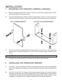
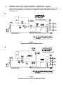
Installation & Service Manual
SCS 11, SCS 203 MG, SCS 303/313 EG
WARNING
Disconnect console before jump starting, charging battery, or welding
on equipment.
016-0159-008
06/03
TABLE OF CONTENTS
INSTALLATION ...................................................................................................................... 2
1. MOUNTING THE SPRAYER CONTROL CONSOLE .................................................. 2
2. INSTALLING THE PRESSURE SENSOR ................................................................... 2
3. INSTALLING THE MOTORIZED CONTROL VALVE .................................................. 3
4. WIRING THE SPRAYER CONTROL SYSTEM ........................................................... 4
INITIAL SYSTEM SET-UP ..................................................................................................... 6
1. ADJUSTING THE SYSTEM ......................................................................................... 6
2. CALIBRATING THE PRESSURE GAUGE .................................................................. 7
APPENDIXES
1. PRESSURE TRANSDUCER CALIBRATION PROCEDURE ............................................ 8
2. GAUGE GUARD ASSEMBLY INSTRUCTIONS ............................................................... 9
3. SCS-313 CONSOLE PRESSURE CALIBRATION
................................................................. ...................................................................... 10
REPLACEMENT PARTS SHEETS
1
INSTALLATION
1.
MOUNTING THE SPRAYER CONTROL CONSOLE
1)
Select a mounting location for the Console in the tractor cab where the pressure gauge is clearly
visible and switches are within easy reach.
2)
Use the Console bracket as a pattern to drill the mounting holes. Drill one 1/4" hole and bolt the
bracket in the position desired. Now drill the second hole and install the second mounting bolt.
SCS 11 CONSOLE BRACKET
3)
SCS 203 & 303 CONSOLE BRACKET
Route the two Power Wires (Red & White) from the Console to a 12 volt source. Connect the White
wire to ground. Connect the Red wire to a +12 VDC "hot" wire (battery, ignition solenoid, or fuse
block).
CAUTION: Some ignition solenoids are 24 VDC.
4)
Route the 8 foot (16 foot on SCS 11) Console Control Cable out the tractor cab.
2.
INSTALLING THE PRESSURE SENSOR
1)
The SCS 11, 202, and 203 Sprayer Control systems sense pressure by means of a black plastic
tube which is tapped into the sprayer line and connected to the pressure tube provided with the
system.
2)
The SCS 303 and SCS 313 Sprayer Control sense pressure through an electronic Pressure
Transducer and therefore does not bring a liquid tube into the Console gauge. Attach Pressure
Transducer with quick disconnect so periodic flushing is possible when using suspensions. Refer
to Appendix 1 and Appendix 3 for calibration instructions for the Pressure Transducer.
2
3.
INSTALLING THE MOTORIZED CONTROL VALVE
Install the motorized Control Valve as shown in the Sprayer Plumbing Diagrams below. The
plumbing will vary depending on whether your sprayer has a positive displacement pump or a
centrifugal pump.
FIGURE 1
STANDARD SPRAYER PLUMBING DIAGRAM
FIGURE 2
ALTERNATE BY-PASS SPRAYER PLUMBING DIAGRAM
3
4.
WIRING THE SPRAYER CONTROL SYSTEM
WIRING DIAGRAM FOR SCS 11
WIRING DIAGRAM FOR SCS 200 SERIES
(WIRING DIAGRAMS CONT. ON NEXT PAGE)
4
WIRING DIAGRAM FOR SCS 303
WIRING DIAGRAM FOR SCS 313
5
INITIAL SYSTEM SET-UP
1.
ADJUSTING THE SYSTEM
l)
Fill tank with water only.
2)
Place MASTER ON/OFF Switch to ON, BOOM ON/OFF switches to OFF, and open tank shut off
valve.
3)
With pump not running, fully open main line hand valve and totally close agitator line hand valve.
(If positive displacement type pump is used, fully open pressure relief valve).
4)
If centrifugal pump is used, proceed with Step 5. If positive displacement pump is used, proceed
as follows:
a) Place MASTER ON/OFF switches to OFF.
b) Set Pressure Relief Valve to 65 PSI [448 kPA].
c) Place MASTER ON/OFF switch to ON.
5)
Verify that each boom solenoid valve operates by operating BOOM ON/OFF switches and that no
nozzles are plugged.
6)
Place all BOOM ON/OFF switches ON.
7)
Hold the MAN ADJ switch in INC position until the pressure stops increasing and begins to
decrease.
8)
Adjust agitator line hand valve for desired agitation.
9)
Close the main line hand valve, if necessary, to set the maximum desired operating pressure. (The
maximum pressure should be approximately 10 PSI [69 kPA], above the nominal spraying
pressure).
10)
Hold the MAN ADJ switch in DEC until the pressure stops decreasing and begins to increase. If
desired minimum pressure cannot be obtained, install larger bypass hose.
11)
Verify the desired maximum pressure of the Sprayer System by repeating Step 7.
6
2.
CALIBRATING THE PRESSURE GAUGE
The pressure tap on the Raven Sprayer Control systems is located away from the nozzles, thus,
there can be a pressure difference between nozzle pressure and gauge pressure at the Console.
Therefore, for best results, we recommend the following procedure:
l)
When the sprayer is ready and the tank filled with water (NO CHEMICALS AT THIS TIME), attach
an accurate pressure gauge to a nozzle in place of the spray tip.
2)
Start up the pump, turn on the electric shut-off valves (Boom Valves) and adjust the pressure control
valve so that the desired pressure is maintained on the gauge at the nozzle.
3)
Because of pressure drops through the system, the pressure shown on the gauge in the Console
may read slightly higher than the gauge at the nozzle. Use this Console pressure reading as your
reference point for maintaining the desired pressure at the nozzle.
7
APPENDIX 1
PRESSURE TRANSDUCER CALIBRATION PROCEDURE
The SCS 303 Control Console and Transducer are factory calibrated. However, if re-calibration is
necessary, complete the following procedure:
1)
Install Pressure Transducer and Control Valve, see page 3.
2)
Install Test Gauge (standard pressure gauge) on boom line.
3)
Fill sprayer tank with water only.
4)
To remove Transducer cover, rotate cover until slot and tab are aligned. Lift off cover.
TOP VIEW OF TRANSDUCER
5)
Position Console MASTER and BOOM switches ON.
6)
Run pump at normal operating RPM.
7)
Hold PRESSURE ADJUST switch down until Test Gauge reads 10 PSI. If necessary, close main
line hand valve to obtain 10 PSI.
8)
Turn ZERO ADJUST with a small screwdriver until SCS 303 meter reads 10 PSI.
9)
Hold PRESSURE ADJUST switch up until Test Gauge reads 40 PSI. If necessary, open main line
hand valve to obtain 40 PSI.
10)
If SCS 303 meter does not read within + 2 PSI of Test Gauge, turn the SPAN ADJUST.
11)
If span adjustment is required, repeat Steps 7-10.
12)
The Transducer is now calibrated and ready for field use.
13)
Replace the Transducer cover and remove the Test Gauge.
14)
Repeat this calibration procedure at the start of each spray season.
8
APPENDIX 2
GAUGE GUARD ASSEMBLY INSTRUCTIONS
1) APPLY THREAD SEALANT TO PIPE NIPPLE.
ASSEMBLE TRANSDUCER.
2) FILL THE TRANSDUCER AND GAUGE GUARD
CAVITY WITH 5W-30 OIL.
3) ASSEMBLE GAUGE GUARD TO TRANSDUCER.
CAUTION: AN EXCESSIVE LOSS OF OIL DURING
ASSEMBLY MAY AFFECT TRANSDUCER CALIBRATION.
4) WITH TRANSDUCER POSITIONED AS SHOWN,
REMOVE BLEED SCREW. SOME AIR AND EXCESS
OIL MUST ESCAPE.
5)
6) INSTALL TRANSDUCER AND CALIBRATE AS
DESCRIBED IN RECALIBRATION OF PRESSURE
TRANSDUCER.
REPLACE AND TIGHTEN BLEED SCREW.
9
APPENDIX 3
SCS-313 CONSOLE PRESSURE CALIBRATION
PROCEDURE
The SCS 313 Control Console is factory calibrated. However, if re-calibration is necessary, complete the
following procedure:
1)
Install Pressure Transducer and Control Valve, see page 3.
2)
Install Test Gauge (standard pressure gauge) on boom line.
3)
Fill sprayer tank with water only.
4)
Remove screws from console faceplate. Pull faceplate outward.
TOP VIEW OF PC BOARD
5)
Position Console MASTER and BOOM switches ON.
6)
Run pump at normal operating RPM.
7)
Hold PRESSURE ADJUST switch down until Test Gauge reads 10 PSI. If necessary, close main
line hand valve to obtain 10 PSI.
8)
Turn ZERO ADJUST with a small screwdriver until SCS 313 meter reads 10 PSI.
CAUTION: Do NOT touch screwdriver to components mounted to console faceplate.
9)
Hold PRESSURE ADJUST switch up until Test Gauge reads 40 PSI. If necessary, open main line
hand valve to obtain 40 PSI.
10)
If SCS 313 meter does not read within + 2 PSI of Test Gauge, turn the SPAN ADJUST.
11)
If span adjustment is required, repeat Steps 7-10.
12)
The Console is now calibrated and ready for field use.
13)
Replace the faceplate and mounting screws. Remove the Test Gauge.
14)
Repeat this calibration procedure at the start of each spray season as needed.
10
SCS 202, 203 REPLACEMENT PARTS
ITEM
1
2
3
4
5
6
7
8
9
10
11
12
13
14
15
16
17
18
19
DESCRIPTION
Mounting Bracket
Boom Switch
Mounting Knob
Master Switch
English PSI Gauge, Female Fitting,
Male Fitting, 195" Tubing
** Liquid Gauge (optional)
Fuse Holder
Fuse, 15 Amp.
Pressure Switch
Console Control Cable (8 ft.)
Flow Ext. Cable (12 ft.)
Flow Control Cable (6 ft.)
Flow Control Cable (12 ft.)
Union Fitting
Tubing (length as required)
3/4" Valve Assembly
1" Valve Assembly
1 1/2" Valve Assembly
SCS 200 series Console
Gauge only
Gauge Fitting
RAVEN PART #
107-0159-007
412-2011-038
309-1000-006
412-2011-037
117-0159-006
417-0001-018
510-2001-003
510-1003-001
412-2011-039
115-0159-010
107-0159-025
115-0159-013
115-0159-015
333-0001-008
214-0001-001
063-0159-001
063-0159-447
063-0171-895
063-0159-203
417-0001-002
333-0001-004
SCS 303 REPLACEMENT PARTS
ITEM
1
2
3
4
5
6
7
8
9
10
11
12
13
14
15
16
DESCRIPTION
Mounting Bracket
Boom Switch
Mounting Knob
Master Switch
Pressure Gauge
Fuse Holder
Fuse, 15 Amp.
Pressure Adjust Switch
Console Control Cable (8 ft.)
Flow Ext. Cable (12 ft.)
Flow Control Cable (6 ft.)
Pressure Transducer
3/4" Valve Assembly
1" Valve Assembly
1 1/2" Valve Assembly
Console
RAVEN PART #
107-0159-007
412-2011-038
309-1000-006
412-2011-037
417-0001-016
510-2001-003
510-1003-003
412-2011-039
115-0159-011
107-0159-043
115-0159-008
063-0159-316
063-0159-001
063-0159-447
063-0171-895
063-0159-315
SCS 11 REPLACEMENT PARTS
ITEM
1
2
3
4
5
6
7
8
9
10
11
12
DESCRIPTION
Printed Enclosure
Back Cover Bracket
On/Off Switch
Pressure Adjust Switch
English PSI Gauge, Female Fitting,
Male Fitting, 195" Tubing
Fuse Holder
Fuse, 5 Amp.
Console Control Cable (16 ft.)
3/4" Valve Assembly
1" Valve Assembly
1 1/2" Valve Assembly
Tubing (length as required)
RAVEN PART #
107-0159-092
106-0159-001
412-2011-038
412-2011-041
117-0159-007
510-2001-010
510-1003-001
115-0159-005
063-0159-001
063-0159-447
063-0159-448
214-0001-001
RAVEN INDUSTRIES
Limited Warranty
What Does this Warranty Cover?
This warranty covers all defects in workmanship or materials in your
Raven Applied Technology Product under normal use, maintenance,
and service.
How Long is the Coverage Period?
Raven Applied Technology Products are covered by this warranty for
12 months after the date of purchase. This warranty coverage applies
only to the original owner and is nontransferable.
How Can I Get Service?
Bring the defective part and proof of purchase to your Raven Dealer.
If your Dealer agrees with the warranty claim, the Dealer will send the
part and proof of purchase to their distributor or to Raven Industries
for final approval.
What Will Raven Industries Do?
Upon confirmation of the warranty claim, Raven Industries will, at our
discretion, repair or replace the defective part and pay for return
freight.
What is not Covered by this Warranty?
Raven Industries will not assume any expense or liability for repairs
made outside our facilities without written consent. Raven Industries
is not responsible for damage to any associated equipment or
products and will not be liable for loss of profit or other special
damages. The obligation of this warranty is in lieu of all other
warranties, expressed or implied, and no person or organization is
authorized to assume any liability for Raven Industries.
Damages caused by normal wear and tear, misuse, abuse, neglect,
accident, or improper installation and maintenance are not covered
by this warranty.
SCS 11, SCS 203 MG, SCS 303/313 EG
Installation & Service Manual
(P/N 016-0159-008 Rev E 2/09)
Raven Industries
Applied Technology Division
P.O. Box 5107
Sioux Falls, SD 57117-5107
Toll Free (U.S. and Canada): (800)-243-5435
or Outside the U.S. :1 605-575-0722
Fax: 605-331-0426
www.ravenprecision.com
[email protected]
Notice: This document and the information provided are the property of Raven Industries, Inc. and may only be used as authorized
by Raven Industries, Inc. All rights reserved under copyright laws.