1
इंटरनेट
मानक
Disclosure to Promote the Right To Information
Whereas the Parliament of India has set out to provide a practical regime of right to
information for citizens to secure access to information under the control of public authorities,
in order to promote transparency and accountability in the working of every public authority,
and whereas the attached publication of the Bureau of Indian Standards is of particular interest
to the public, particularly disadvantaged communities and those engaged in the pursuit of
education and knowledge, the attached public safety standard is made available to promote the
timely dissemination of this information in an accurate manner to the public.
“जान1 का अ+धकार, जी1 का अ+धकार”
“प0रा1 को छोड न' 5 तरफ”
“The Right to Information, The Right to Live”
“Step Out From the Old to the New”
Mazdoor Kisan Shakti Sangathan
Jawaharlal Nehru
IS 1448-148 (2002): Methods of Test for Petroleum and its
Products, Part 148: Determination of Electrical
Conductivity of Aviation and Distillate Fules Containing
Static Dissipator Additive [PCD 1: Methods of Measurement
and Test for Petroleum, Petroleum Products and Lubricants]
“!ान $ एक न' भारत का +नम-ण”
Satyanarayan Gangaram Pitroda
“Invent a New India Using Knowledge”
“!ान एक ऐसा खजाना > जो कभी च0राया नहB जा सकता ह”
है”
ह
Bhartṛhari—Nītiśatakam
“Knowledge is such a treasure which cannot be stolen”
IS 1448 [P : 148] :2002
mJ7m5
\
m
Qlw W?l-wwtm+mmwfadl
[ti
: 148]
fwmmti~titi~~dti
Wa@mmmmm%m
Indian Standard
METHODS OF TEST FOR PETROLEUM
AND ITS PRODUCTS
b
t
I
[P: 148]
DETERMINATION OF ELECTRICAL CONDUCTIVITY OF AVIATION AND
DISTILLATE FUELS CONTAINING STATIC DISSIPATOR ADDITIVE
ICS 75.160.20
@BIS 2002
BUREAU
OF
INDIAN
STANDARDS
MANAK BHAVAN, 9 BAHADLJR SHAH ZAFAR MARG
NEW DELHI 110002
./l(/lc 2002
Price Group 4
Methods of Measurement and Test for Petroleum, Petroleum Products and Lubricants Sectional Committee,
F’CD1
FOREWORD
This Indian Standard [P : 148] was adopted by the Bureau of Indian Standards, after the draft finalized by the
Methods of Test for Petroleum, Petroleum Products and Lubricants Sectional Committee had been approved
by the Petroleum, Coal and Related Products Division Council.
.
This standard, method of test was prepared based on joint publication of ASTM D 2624 and 1P 274.
The composition of the Committee responsible for formulation of this standard is given in Annex E.
1n report ing the results of a test or analysis made in accordance with this standard, if the final value, observed
or calculated, is to be rounded off, it shall be done in accordance with IS 2: 1960 ‘Rules for rounding off
numerics] values (revised)’.
I
+-t
IS 1448 [P:148]
:2002
4
,,
Indian Standard
METHODS OF TEST FOR PETROLEUM
AND ITS PRODUCTS
[P: 148]
DETERMINATION OF ELECTRICAL CONDUCTIVITY OF AVIATION AND
DISTILLATE FUELS CONTAINING STATIC DISSIPATOR ADDITIVE
1 SCOPE
1.1 These test methods cover the determination of
the electrical conductivity of aviation and distillate
fuels containing a static dissipator additive. The test
methods normally give a measurement of the
conductivity when the fhel is uncharged, that is,
electrically at rest (known as the rest conductivity).
1.2 Two test methods are available for field tests of
fuel conductivity. These are:
a) portable meters for the direct measurement in
tanks or the field or laboratory measurement of
fuel samples, and
b) in-line meters for the continuous measurement
of fuel conductivities in a fuel distribution
system. In using either type of instrument, care
must be taken in allowing the relaxation of
residual electrical charges before measurement
and in preventing fuel contamination. For
purposes,
specification
conductivity
measurements should be made with the portable
meters.
NOTE — After pumping operations it may be necessary
to wait before taking measurements to allow the fuel to
become electrically
at rest and reach an equilibrium
conductivity.
30 minutes waiting period is normally
sufficient.
1.3 The values stated in S1units are to be regarded
as the standard.
1.4 This standard may involve hazardous materials,
operations, and equipment. This standard does not
purport to address all of the safety problems
associated with its use. It is the responsibility of the
user of this standard to establish appropriate safety
and health practices and determine the applicability
of regulatory limitations prior to use.
2 SUMMARYOF
eliminated in dynamic monitoring systems by continuous
replacement of the sample in the measuring cell. The
procedure, with the correct selection of electrode size
and current measurement apparatus, can be used to
measure conductivities from 1 picosiemens/metre or
greater. The commercially available equipment referred
to in this method covers a conductivity range upto 2000
picosiemens/metre
with good precision (see 10)
although some meters can only read to 500 or 1 000
picosiemens/metre.
3 SIGNIFICANCE
The ability of a fiel to dissipate charge which has become
generated during pumping and filtering operations is
controlled by its electrical conductivity, which depends
upon its content of ion species. If the conductivity is
sufficient high, charges dissipate fast enough to prevent
their accumulation and dangerously high potentials in
a receiving tank avoided.
4 DEFINITIONS
4.1 Rest Conductivity
The reciprocal of the resistance of uncharged fuel in the
absence of ionic depletion or polarization. It is the
electrical conductivity at the initial instant of current
measurement after a DC voltage is impressed between
electrodes.
4.2 Picosiemens Per Meter (symbol pS/m)
The unit of electrical conductivity is also called a conductivity unit (CU). A siemen is the S1 definition of
reciprocal ohm sometimes called mho.
Hence
1 ps/m= 1 x 10-12L?-(m-’ = 1 cu = 1 picomho/m.
NOTE — One picosiemen equals 10-12 ohm and in the S1
replaces the former picomho. The term ‘conductivity
unit’
abbreviated
‘CU’ is also used for the picosiemen/metre.
METHOD
A voltage is applied across two electrodes immersed
in the fuel and the resulting current expressed as a
conductivity value. With portable meters, the current
measurement is made almost instantaneously upon
application of the voltage to avoid errors arising from
ion depletion. Ion depletion or polarization is
5 PORTABLE METER
METHOD
5.1 Apparatus
5.1.1 Conductivity
Apparatus
Cell and Current-Measuring
Any suitable equipment capable of giving a conductivity
1
-.
—&
IS 1448 [P:148]
:2002
reading almost instantaneously with the application of
the voltage.
5.1.2 Thermometer
IP49C having a range suitable for measuring fuel temperature in the field. A thermometer holder shall be
available so that the temperature can be directly
determined for fuel in bulk storage, rail tanks, cars and
trucks.
8.1.2 All sample containers shall be thoroughly
cleaned with cleaning solvent and dried with a stream
of air. Prior to taking the samples, all containers,
including caps, shall be rinsed at least three times with
the fuel under test.
8.1.3 Conductivity measurements shall be made as
soon as possible after sampling and preferable within
24 h.
5.1.3 Measuring Vessel
9 PROCEDURE
Any suitable cylindrical vessel capable of holding
sufficient fuel to cover the electrodes of the conductivity cell. For the equipment referred to in Note 1,
a minimum volume of 1 litre is required.
9.1 The specific calibration procedures detailed in
Annexes A, B and C are an essential part of the
following generalized procedures. The appropriate
calibration steps for the instrument used shall be
followed prior to commencing the subsequent
procedures.
The following portable equipment (see Notes 1 to 3
below) has been recommended for this purpose.
9.2 In-Situ FieId Measurements on Tan@ Tank Cam
Tank Trucks, etc
NOTES
1 Maihak MLA-900 Conductivity Indicator Manufacturefi
H. Maihak, 2000 Hamburg 60. Postiach
601709.W.
Germany
For field measurements the conductivity meters referred
to in Note 2 of 5.1.3 are considered suitable although
their use inhazardous locations maybe restricted by
local safety regulations. Each meter has an extension
cable or can be equipped with one to lower the cell into
the tank. High impedance hand-held meters are
susceptible to electrical transients caused by the
extension cable flexing during measurements. Failure
to hold the apparatus steady during measurements may
result in significantly poorer precision than shown
in 11.1.2. The following instructions apply to the meters
referenced in Note 2 of 5.1.3.
U.S. Agent: Ampower Corpn. 50 Broad Street, New York,
N. Y.1OOO4
2
Ethyl Intertech Distillate
8150, 8151 and 8152
Conductivity
Manufacturer:
Ethyl Intertech
Princeton, N.J. 08540.
Corpn.
Meter
19 Rozzel
Model
Road,
These meters are no longer available.
Calibration
procedures for the existing meters can be obtained from
the manufacturer.
3
Emcee Conductivity
Meter Models
115 I and 1152
Manufacturer:
Emcee Electronics.
8875 Midnight
Road Sarasota, Florida 33581, USA.
Pass
6 REAGENTS AND MATERIALS
9.2.1 Check meter calibration as detailed in Annexes
A and B depending on the meter used. Earth the meter
to the tank and lower the conductivity cell into the
tank to the desired level, taking care to avoid partial
immersion or contact with tank water bottoms, if
present. Move the conductivity cell in an up-and
-down motion to remove previous fuel residues.
6.1 Cleaning Solvent
Analytical grade toluene. If the presence of water is
suspected use isopropyl alcohol followed by toluene.
CAUTION: Toluene is a toxic, volatilehydrocarbon
which is absorbed by inhaling the vapour or
through the skin by contact with the liquid. Use
in adequate ventilation and avoid skin contact.
NOTES
1
CAUTION : To prevent static discharge between a charged
fuel and a conductive
probe inserted into a tank, the
appropriate safety precautions of earthing and waiting for
charge dissipation should be observed.
For example, the
American Petroleum
Institute in RP 2003 recommends
that a 30 minutes intewal be allowed after pumping into
a storage tank before an operator mounts a tank to insert
a sampling device. This cell ensure that the fuel is electrically
at rest (see A’ofe under 1.2).
2
If the cell is in contact with water and the instrument is
switched on, an immediate off-scale reading will be obtained.
If the cell haa been in contact with water, it must be
thoroughly rinsed with cleaning solvent and dried with a
stream of air. In hot, humid conditions, condensation
on
the cell can occur, which can cause abnormally high zero,
calibration, and sample readings. This can be avoided by
storing the cell at a temperature 2 to 5°C in excess of the
maximum ambient temperature where this is practicable.
7 CALIBRATION
The calibration procedure will be dependent upon the
equipment used. The procedures for the instruments
are described in Annexes A, B and C.
NOTE -– The test method results are known to be sensitive
to trace contaminations
from sampling containers.
8 SAMPLING
8.1 Fuel conductivity measurements shall be made
irr-situ to avoid changes during sample shipment. If it
is necessary to take samples for subsequent analysis,
the following precautions shall be taken.
8.1.1 The sample size should be as large as practicable
and not less than 1 litre.
2
.
..’-
—A
.-
IS 1448 [P: 148] :2002
9.2.2 After flushing the cell, hold it steady and after
activating the instrument record the highest reading
after initial stabilization. This should occur within 3
seconds. On instruments with more than one scale
range, select the scale which gives the greatest
sensitivity for the conductivity value being determined.
Ensure that the appropriate scale multiplying factor
(or scale range) is used. Record the fuel temperature.
operator-instrument pairs at a common test site is as
follows.
11.1.1 Repeatability
The difference between successive measured
conductivity values obtained by the same operator
with the same apparatus under constant operating
conditions on identical test material at the same fuel
temperature would, in the long run, in the normal and
correct operation of the test method, exceed the values
in Table 1 only in one case in twenty.
9.3 Laboratory and Field Measurements on Sample
Fuels
9.3.1 Preparation
of Containers (Metal or Glass)
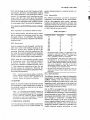
Table 1 Precision ‘~3)
Prior to taking samples, take extreme care to ensure
that all containers and measuring vessels have been
thoroughly cleaned. It is preferable that containers
are laboratory cleaned prior to shipment to the field for
sampling (see 8).
Conductivity (pS/m)
(1)
50
100
200
300
400
500
600
800
I 000
I 500
9.3.2 Measurement
Rinse the conductivity cell thoroughly with the fiel
under test to remove fuel residues remaining on the
cell from previous tests. Transfer the fuel to the
measuring vessel and record the conductivity of the
fuel using the procedure applicable to the particular
apparatus. If one of the conductivity meters referenced
in Note 2 of 5.1.3 is used, follow these instructions.
Repeatability
(2)
3
5
10
14
18
21
25
32
39
55
Reproducibitity2)
(3)
10
17
32
45
69
.
—
125
177
1) The precision
limits in Table 1 are applicable at room
temperature.
Significantly
highe~ limits (X2) may be
applicable at temperatures near –20 C. Underlined values
in the repeatability columns are interpolated.
2) The reproducibility
values above were estimates from
results obtained at the same location on the same day,
by different
operator/instruments
testing identical
samples. Results obtained at different times and locations
according
to the above
may not be comparable
reproducibility estimates, since they may contain errors
due to sampling and environmental
factors.
31 The data used to determine the precision of this test
9.3.2.1 Rinse the cell concurrently with the rinsing
of the measuring vessel. Then transfer the sample to
be tested to the clean, rinsed measuring vessel.
Check meter calibration as detailed in Annex A, B or
C. Fully immerse the conductivity cell into the test
fuel and measure the conductivity following the
procedure detailed in 9.2.2 and the appropriate Annex.
Record the fuel temperature.
method were obtained without extension
held meters.
cables on hand-
11.1.2 Reproducibility
NOTE — In order to avoid erroneous readings, it is important
{o ensure that the bottom of the conductivity cell does not
touch the sample
container.
This is applicable
to all
containers, whatever the material of construction.
The difference between two single and independent
measurements of conductivity obtained by different
opetStors working at the same location (see Note
under 10) on identical test material at the same fuel
temperature would, in the long run, in the normal and
correct operation of the test method, exceed the values
in Table 1 only in one case in twenty.
10 REPORT
Repost the electrical conductivity of the fuel and the
fuel temperature at which measurement was made. If
the electrical conductivity reads zero on the meters
report less than 1 ps/m.
11.2 In 1987 a test programme was carried out to
investigate reproducibility of results when samples
are shipped between laboratories. While repeatability
values were similar to those in Table 1, it was concluded
that adequate reproducibility values were not obtained
due to changes in conductivity of samples during
shipment and storage. In the event of dispute or
concern regarding shipped sample conductivity, it is
recommended that operators come to the bulk fuel
storage site to measure conductivity on bulk fuel or on
freshly obtained samples according
to cited
NOTE — It is recognized that the electrical conductivity of
a fuel varies with temperature
and that the relationship
differs for various types of aviation fuel. If it is necessary
to correct conductivity readings to a particular temperature,
each laboratory
would have to establish this relationship
for the fuels and temperature range of interest.
11 PRECISION
!,.,
AND BIAS
11.1 The precision of this test method as determined
by statistical analysis of test results obtained by
3
.. .
-A
IS 1448 [P:148]
:2002
procedures. This assures that asample indenticalto
the bulk supply istested byeither or both pafiies and
the precision data shown in Table 1 shall apply.
14 PROCEDURE
Flu~hthe~ell thoroughlyby
initiating a controlled
flow of the fiel to be measured. Purging of air from
the cell and adequate flushing is normally achieved in
a few minutes but a longer flush is recommended when
Calibrating the ins~ment. The controlled flow must
Confom to the maufactirer’s recommendation. Too
fast or too SJOWa flow will result in inaccuracies in the
11.3 Bias
Since there is no accepted reference material or suitable
test method for determining the bias of the procedure
given in ASTM D 2624 for measuring electrical
conductivity, no statement on bias is being made.
conductivity measurement.
12 APPARATUS
15 CALIBRATION
Continuous measurements can be made with the
equipment listed in 12.1 where suitable precautions
have been taken to remove static charges before the
representative fuel stream is passed firough an inline measuring cell. A controlled, continuous flow
through the cell prevents ion depletion, thereby
providing the equivalent of rest conductivity as a
continous measurement.
The specific calibration procedure detailed in
Annex D is an essential part of the general procedure
and should be completed prior to initiating automatic
monitoring and control of the continuous fuel streams.
The high and low level alarm circuits can be calibrated
as recommended by the manufacturer.
.
16 MEASUREMENT
After calibration, select the instrument scale of the
approximate range anticipated for the fiel stream and
initiate continuous measurements of fiel conductivity.
Measurements are made at the test cell temperature
(indicated by the installed thermometer) which should
approximate to the temperature of the fiel in the system.
12.1 The following continuous measuring equipment
has been found satisfactory for this purpose:
Staticon Conductivity Monitor (Model 1150),
manufactured by Emcee Electronics 8875 Midnight
Pass Road Sarasota, Florida 33581, USA.
17 REPORT
13 INSTALLATION
Report the electrical conductivity of the fhel and the
fuel temperature at which measurement was made [see
Note under 10].
In general this instrument is designed for permanent
installation in the fuel distribution system. The
manufacturer’s
recommendations
concerning
installation and flow control must be followed,
particularly with respect to the provision of adequate
relaxation time. The sample tapping point should be
installed at least 30 m downstream of any additive
injection system, unless a mixing device is used which
has been shown to give adequate mixing of the
additive concerned prior to sampling. A thermometer
having a suitable range for measuring fuel temperature
in the field shall be installed downstream of the test
cell.
b
18 PRECISION
18.1 The repeatability of the continuous meter has
been established to be within the range given for the
portable instruments (see 11.1.1).
18.2 The reproducibility has not been established.
18.3 Bias
The bias statement is being developed.
4
.. --
IS 1448[P:148]
:2002
ANNEX A
(Clauses 7 and 9)
CALIBRATION
OF THE MAIHAK METER
A-1 Before carrying out the calibration procedure the
conductivity cell must be clean and dry (see Note
zero shall be obtained. For Series 1 and 2 instruments
a positive reading of about 10 to 30 pS/m shall be
obtained. This value must be subtracted from all
measured conductivity reading.
under 9.2.1).
A-2 The Maihak meter has been built in four models
or series with different characteristics.
The
corresponding instrument numbers are as follows:
Series
1
2
3
4
If readings within these limits are not obtained, the
instrument requires servicing.
Instrument Number
NOTE — If the pointer of the meter oscillates
during
measurement, it is likely that the battery needs replacing.
64001 to 64068,64070
64069,64071 t064171
Prefix 2 –
Prefix 3 –
AA VERIFYING PERFORMANCEOFTHEMETER
Fully immerse the conductivity cell into the test fbel,
holding it steady and then press the green READ
button and record the highest reading after the needle
has recovered from the initial overswing caused by
inertia. The initial recovery shall not exceed 20 pS/m
and will be completed in less than one sec. For
conductivities in the range 500 to 1000 pS/m the red
2X button shall be pressed and kept pressed while the
READ button is pressed. Multiply the resultant
scale reading by 2 to obtain the correct conductivity
reading (This technique is also applicable for
conductivities less than 500 as a check on the direct
reading).
Series 2 and 3 instruments should have been
subsequent y modified with parts supplied by. the
manufacture~ in this case, the instrument numbers bear
the suffix ‘M’.
A-3 CHECKING THE CALIBRATION
To check the calibration reading, press the green
READ button with the conductivity cell in the rest
position against the calibration resistor in the housing.
A meter reading of 465+10 pS/m shall be obtained. For
confirmation press the red 2X button and then also the
green READ button, as above. The meter shall read
232+1OpS/m. To check the live zero reading, lift the
conductivity cell slightly in the housing to break
contact with the calibration resistor. Press the green
READ button. Repeat while pressing the red 2X
button. For series 3 and 4 instruments a reading of
NOTE — It has been found that the early series instruments
don’t work properly at very low ambient temperatures.
However, Series 3 and 4 in$ruments operate satisfactorily
at temperatures down to –29 C provided that the exposure
time is limited to 30 minutes maximum.
ANNEX B
(Clauses 7 and9)
CALIBRATION
AND USE OF THE EMCEE ANALOGUE CONDUCTIVITY METER (MODEL 1151A)
B-1 INTRODUCTION
isopropyl alcohol and allowed to air dry before retesting
for zero.
The principal operating parameters of the Emcee
Conductivity Meter have been properly adjusted before
shipment. Nevertheless, readjustment may become
necessary from time-to-time. The following adjustments
cover those that can be made conveniently in the field.
NOTE — Certain models with one hold in the side panel do
not have a facility for zero adjustment without reference
to the service manual.
B-2.2 Check Calibration
B-2 CALIBRATION CHECK PROCEDURE
The CU RANGE switch position for calibration differs
with certain models.
B-2.1 Check zero. Set CU RANGE Switch to X-1.
Hold meter with probe vertical and depress MEASURE
switch. The meter shall deflect and gradually go to
zero (approx’imately 3 seconds). If the meter does not
go to zero (within 1 division) remove the probe and
repeat zero test. If meter does not go to zero insert a
small screwdriver into side panel upper hole or that
marked ZERO and adjust for OCU+ 1division. If zero
adjustment is OK without probe but not when probe
is attached, the probe shall be thoroughly rinsed with
Those meters with serial number on frontpanel—
Set
the CU RANGE switch to CAL.
Those meters with internal serial numbers — Set the
CU RANGE switch to X-1.
Depress both MEASURE and CALIBRATE switches
at the same time. Allow meter pointer to stabilize
(approximately 3 seconds). The meter reading shall be
equal to the calibration number stamped on the probe
5
..-
“’
&
.-A
IS 1448 [P:148]
:2002
(+1 division). Ifnecessary insert asmallscrewdtiver
in theside panel hole andadjust meter pointer to the
number stamped on the probe. If, as with certain
models, two holes are available in the side panel then
the lower one shall be used.
B-3 CONDUCTIVITY
MEASUWMENT
Insert probe into fiel sample until fuel level is aligned
with the centre of the holes nearest the top of the probe.
Set CU RANGE switch to X- 10. Depress MEASURE
switch and allow meter pointer to stabilize
(approximately 3 see). If meter reading is between 5
and 50 multiply by 10 and record result.
B-2.3 Battery Replacement
If preliminary calibration check procedures cannot be
achieved, the batteries shall be checked or changed.
If meter reading is between Oand 5 set CU RANGE
switch to X-1. Depress MEASURE switch and allow
meter pointer to stabilize (3 seconds). Record meter
reading.
ANNEX C
(Clauses 7 and9)
CALIBRATION
OF THE EMCEE DIGITAL
CONDUCTIVITY
C-1 Connect probe to connector on the Emcee Digital
METER
(MODEL
1152)
times the number stamped on the probe +0.005 (after
approximately 3 s).
Conductivity Meter and depress the MEASURE switch
(M) with the probe out of the fuel sample. Zero reading
shall be 000+001 (in approximately 3 seconds).
For example: Probe number equals 40, meter reading
must be 400+005 (395 to 405). If instrument does not
meet specification, proceed to C-5.
C-2 If the instrument does not meet the specification,
remove the probe and depress MEASURE switch (M).
If the instrument meets the specification without the
probe attached, the probe shall be thoroughly rinsed
with isopropyl alcohol and allowed to air dry before
retesting for zero. If the instrument does not meet the
specification without the probe attached, then the
adjustment procedure of C-4 shall be performed.
C-4 Zero adjustment is performed without the probe
attached and the MEASURE switch (M) depressed.
Insert a screwdriver in the hole marked ‘Zero’ and adjust
the control until the DISPLAY reads 000+001.
C-5 Calibration is performed without the probe
attached and with the CALIBRATION switch
depressed. Insert a screwdriver in the hole marked
‘CALIBRATE’ and adjust to within +002 of ten times
the number stamped on the probe.
C-3 Note the calibration number stamped on the
probe. Depress the CALIBRATION switch (C) with the
probe out of the fuel sample. The reading shall be ten
ANNEX D
(Clause 15)
CALIBRATION
OF THE STATIC ON CONDUCTIVITY
D-1 Before carrying out the calibration procedure, the
MONITOR
instructed. Turn fimction switch to ‘low alarm’. Adjust
alarm level as required. The high level alarm may be
calibrated in a similar manner. Turn function switch to
‘Operate’ and lift the reset switch (The alarm light will
go out). The recorder will then indicate the
conductivity of the fuel stream. The alarm will be
activated and the pumping circuits disabled if the
conductivity drops below (or above) the pre-set level.
installed conductivity cell shall be flushed and the fuel
flow adjusted to the recommended level.
D-2 Before calibrating, turn the power switch to
‘ON’ and adjust the meter zero as directed. Turn the
function switch to ‘Calibrate’. Meter should indicate
100 pS/m on each of three scales. If not, adjust as
6
----
—A
IS 1448 [P:148]
ANNEX E
(Foreword)
COMMITTEE
COMPOSITION
Methods for Measurement and Test for Petroleum,
Petroleum Products and Lubricants Sectional Committee, PCD 1
Representative(s)
Organization
Indian Institute
of Petroleum,
Air Headquarters
(Ministry
(Chairman)
SHIUSUDHIR
SINGHAL
DR A. DUTTA(Alternate)
Debra Dun
of Defence),
JOINTDIRECTOR(QASAero)
DEPUTYDIRECTOR
(QAS) (Aliernafe)
SHRIS.C. JAIN
(Alternate)
SHRISUIUNOER
SHAP.MA
%UUVINAYTOSmWWAL
EXECUTIVE
SECRETARY
(Alternate)
New Delhi
AIMIL Ltd, Delhi
All India Instrument Manufacturers
Association,
Mumbai
Automotive
Research
Bharat Petroleum
Bogaigaon
Castrol
Association
Corporation
Refinery
and Dealers
of India (ARAI),
Pune
& Petro Chemicals
Ltd, Daligaon
SHRJC. P. BEZBORUAH
SHruS. S. ROY(Alternate)
SHtUM. GUWA
India Ltd, Mumbai
Central Fuel Research
SHIUA. R. ARANRALLE
SHIUR. K. MODI
DR Y. P. RAO(Alternate)
Ltd, Mumbai
Institute,
DR P. SAMUEL
DR K. N. BHATTACHARYA
(Alternate)
Dhanbad
Central Revenue Cofitrol Laboratory,
(Department of Revenue), New Delhi
CHEFCHEMIST
(Alternate)
DEPUTYCHIEFCHEMIST
Directorate
General
SHRIB. K. JOSHI
SHRIS. S. MAZUMDAR
(Alternate)
Hindustan
Petroleum
of Civil Aviation,
Corporation
New Delhi
Ltd, Mumbai
SHSUS. J. INAMDAR
SHRIN. S. J. RAO(Alternate)
Indian Oil Corporation
Digboi
Ltd, Assam Oil Division,
SHRIA. K. CHAKRABORTV
(Alternate)
SHRIP. M. SINHA
Indian Oil Corporation
Mumbai
Ltd, Marketing
SHRIA. K. VERMA
DR T. K. DE (Alfernate)
Indian Oil Corporation
Ltd, R & P Division,
Indian Oil Corporation
Ltd, R & D Centre, Faridabad
Division,
New Delhi
SHRID.J. KAXATI
SHRIA. K. KATHURtA
(Alternate)
SHRIN. R. RALE
Indian Oil Blending Ltd, Mumbai
SHRIR. TYAGI
(Alternate)
SHRIA. K. SEHGAL
Lubrizol India Ltd, Mumbai
SHRIR. R. PARMAR
DR U. S. RAO(Alternate)
Madras Refineries
SHruN. V. KALAIVANAN
S. M (TS-QC) (Alternate)
Mangalore
Ltd, Chennai
Refineries
and Petrochemicals
(DRDO),
Ltd, Mangalaore
Ministry
of Defence
Ministry
of Defence (DGQA),
Ministry
of Petroleum
and Natural Gas, New Delhi
National
Test House,
Kolkata
oil & Natural Gas Commission,
Projects
Reliance
& Development
Petroleum,
Kanpur
New Delhi
Debra Dun
India Ltd, Sindri
Gujarat
SLUU
S. RAMESH
DRP. S. VENXATARAW
(A/ternate)
SHRIH. C. SRIVASTAVA
SHRIK. H. GANOHI
SHRIA. J. S. ARORA(Alternate)
ADVISER
(REFINERIES)
DIRECTOR
(SUPPLY)(Alternate)
SHRIK. C. NASXAR
SHIUP. K.CHAKRALIGRTV
(Alfernate)
DRS. F. H. WV]
(Alternate)
SHSU
S. MATHUR
DR R. P. .%NGH
SHIU
V. S. MAN
7
:2002
—
IS 1448 [P : 148] :2002
Representative(s)
Organization
Research
Designs & Standards Organization, Lucknow
Shriram Institute
forlndl
BIS Directorate
General
Research,
DEW Dmacmr@Chemicals)
Assrr RESEARCH
OFFICER(CM)-IV (Alrerrwte)
DR P. K. KAICKER
New Delhi
SHRIMATILAXMI RAWAT(Alternate)
ANJANKAR, Director & Head (PCD)
[Representing Director General (Ex-oficio)]
Member-Secretary
SHRJR. P. MMHRA
Joint Director (PCD), BIS
Liquid Fuels and Solvents Tests Subcommittee, PCD 1:3
Indian Oil Corporation Ltd, R&D Centre, Faridabad
Bharat Petroleum Corporation Ltd, Mumbai
DR A. A. GUPTA(Convener)
DR P. BHATNAGAR
(Alternate)
SHRJN. D. RAur
SHRJV. Y. VARTAK
(Alternate)
Bongaigaon Refinery and Petrochemicals Ltd, Dhaligaon
SHRIC.P. BEZBARUAH
Central Revenue Control Laboratory,
Department of Revenue, New Delhi
CHIEF
CHEMIST
(Alternate)
DEPUTY
CHiEFCHEMIST
Directorate General of Civil Aviation, New Delhi
SHRIB. K. JDSHI
SHRIS. S. MAZUMDAR
(Ahernate)
DR J. M. N~GPAL
DR R. L. SHAFO.iA
(Af/ernate)
SHRJM. R. SAHA
(Alternate)
SHRIG. S. SINHA
SHRJR. SLJNDARAM
(Alternate)
SHRJM. K. DAXINI
Indian Institute of Petroleum, Debra Dun
Indian Oil Corporation Ltd, R&P Division,
New Delhi
Hindustan Petroleum Corporation Ltd, Mumbai
Ministry of Defence (DGQA), New Delhi
.%JU
N.V.SAWANARAYAN
Mangalore
SHFU
S. R.AMmR
SHRJ G.
National
Refineries
Ltd, Mangalore
Test House, Kolkata
CHAKRAaORTV
(Alternaie)
SHRJN. C. CHATMRJEE
SHRJS. N. MISRA(Alternate)
National Thermal Power Corporation, R & D, New Delhi
SHFU
S. BALASUBRAMA!AN
Indian Oil Corporation Ltd [Marketing), Mumbai
SHRJS. K. BOSE
DR T. K. DEY (Alternate)
RDSO. Lucknow
DEPOTV
Dmc’rmr (P& c)
Assm RESEARCH
OFFICER
(C-3) (Affernate)
8
—
Bureau
oflndian
Standards
institution
established
under
the Bureau of Indian Standards
Act, 1986 to promote
harmonious development of the activities of standardization, marking and quality certification of goods
and attending to connected matters in the country.
BIS is a statutory
Copyright
BIS has the copyright of all its publications. No part of these publications may be reproduced in any form
without the prior permission in writing of BIS. This does not preclude the free use, in the course of
implementing
the standard, of necessary details, such as symbols and sizes, type or grade designations.
Enquiries relating to copyright be addressed to the Director (Publications), BIS.
Review of Indian
Standards
Amendments are issued to standards as the need arises on the basis
periodically; a standard along with amendments is reaffirmed when
needed; if the review indicates that changes are needed, it is taken
should ascertain that they are in possession of the latest amendments
‘BIS Catalogue’ and ‘Standards: Monthly Additions’.
This lndian Standard has been developed
,,
from Doc : No. ~CD 1 ( 1483 ).
Amendments
Amend No.
of comments. Standards are also reviewed
such review indicates that no changes are
up for revision. Users of Indian Standards
or edition by referring to the latest issue of
Issued Since Publication
Text Affected
Date of Issue
~&
I
s1
BUREAU OF INDIAN STANDARDS
Headquarters
:
Manak Bhavan, 9 Bahadur Shah Zafar Marg, New Delhi 110002
Telephones :3230131,3233375,323
9402
Telegrams : Manaksanstha
(Common to all offices)
Regional Offices :
I
\
Telephone
Central
: Manak Bhavan, 9 Bahadur Shah Zafar Marg
NEW DELHI 110002
3237617
3233841
{
Eastern
: 1/14 C.I.T. Scheme VII M, V. 1. P. Road, Kankurgachi
KOLKATA 700054
Northern
: SCO 335-336, Sector 34-A, CHANDIGARH
3378499,3378561
3378626,3379120
{
603843
{ 602025
160022
Southern
: C.I.T. Campus, IV Cross Road, CHENNA1 600113
Western
: Manakalaya, E9 MIDC, Marol, Andheri (East)
MUMBAI 400093
Branches
: AH MEDABAD.
BANGALORE.
BHOPAL.
BHUBANESHWAR.
COIMBATORE.
FARIDABAD.
‘GHAZIABAD.
GUWAHATI.
HYDERABAD.
JAIPUR.
KANPUR.
LUCKNOW. NAGPUR. NALAGARH. PATNA. PUNE. RAJKOT. THIRUVANANTHAPURAM.
{
2541216,2541442
2542519,2541315
8329295,8327858
{ 8327891,8327892
Printed at Prabhat Offset Press, New Delhi-2
f