1
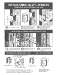
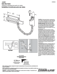
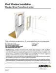
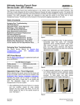
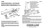
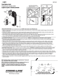
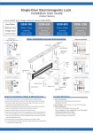
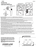
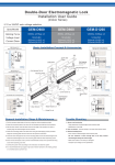
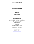
SWINGING DOORS HARDWARE--INSWING AND OUTSWING FRENCH DOORS
LOCKING ROD REPLACEMENT (CN 7-- 0 AND HIGHER MANUFACTURED AFTER 5/3/03)
ATTENTION:
As of May 5, 2003 Inswing and Outswing French Doors with a CN of 7- 0 or greater (>=86 1/2” R.O.) will be manufactured
with a new foam plug within the FRP stile. This foam plug is designed with use of the shoot bolt guide, to minimize rattling
in units with a longer top locking rod.
If your replacement panel did not come with locking hardware, new shoot bolt guides must be used in conjunction with
the old locking rod(s).
To fix rod rattle on doors shorter than 7/0, simply remove old shoot bolt guides and replace with new style (see below).
Old shoot bolt guide
New shoot bolt guide
NOTE: Photographs below show the panel stile cut away for
illustrative purposes.
Shoot Bolt Installation
1.
With the hardware in
the unlocked position,
remove the top shoot
bolt guide from old
panel by unfastening
the #8x1 1/2” Phillips
panhead screw from
the
guide.
See
illustration 1.
With the locking hardware in the unlocked position,
remove the two #8x 5/8” panhead screws fastening the
box to the panel. Pry the box out and set aside.
7.
If the old shoot bolt has the sound dampening washers
attached, simply peel the foam dampeners from the rod.
NOTE: Some special size height rods may have dampeners
attached with plastic ties, remove these with a wire cutter and
discard.
1
2.
6.
Pry the shoot bolt
guide from the panel
with a flat headed
screwdriver or pry bar.
See illustration 2.
8.
Insert the lock box in the new panel and fasten with
screws removed earlier. Fasten the cover plate to the
panel as well.
9.
With the locking hardware in the locked position, insert
the top shoot bolt into the panel at an angle so that the
end of the bolt (with the hex nut) is riding along the
exterior side of the panel. The shoot bolt will have to be
threaded through the intermediate foam block as shown
in illustration 4.
2
3.
Move the hardware to
the locked position so
the shoot bolt is
accessible. Turn the
shoot
bolt
counter--clockwise
until it disengages
from the lock box.
Remove the shoot bolt
from the old panel.
See illustration 3.
Foam
block
3
4.
Remove the bottom shoot bolt guide and shoot bolt in the
same manner.
5.
Remove the lock box hardware from the old panel by first
unscrewing the two #8x 1” flathead brass screws
attaching the cover plate to the panel. Remove the plate
and set aside.
4
7/23/03
19972157
2/2005
8.1.4
Marvin Service Manual
11708609
SWINGING DOORS HARDWARE--INSWING AND OUTSWING FRENCH DOORS
LOCKING ROD REPLACEMENT (CN 7-- 0 AND HIGHER MANUFACTURED AFTER 5/3/03)
IMPORTANT: If you meet resistance, STOP immediately.
Back the bolt out and try again until it is threaded through the
foam block. It is possible to miss the groove on the foam
block, causing the block to detach from the panel and be
pushed down toward the lock box. If this is the case, it will be
nearly impossible to thread the bolt into the lock box. See illustration 5 below. If the block is pushed down the panel cavity, see the section on repositioning the foam block at the end
of this instruction.
15.
Insert a push stick that is approximately 3/4 as long as
the panel into the sill shoot bolt channel, through the
mortise lock area and push the foam block back into
position. Do not remove the push stick. See
illustration 7.
NOTE: Sill bolt channel is 5/8″ x 5/8″ (16 x 16). Use a wooden s
PVC pipe of appropriate dimension that will fit in channel.
Push
stick
Block pushed
down the stile
7
16.
5
10.
Once threaded through the foam block, continue to push
the bolt until it tracks and threads into the mortise lock.
See illustration 6. Turn the shoot bolt until tight, then
back off two full turns.
Thread the head jamb shoot bolt through the foam
block as described in step 9 from previous section.
See illustration 8.
Mortise lock area
8
17.
6
11.
Replace the shoot bolt guide and fasten with screw
removed earlier.
12.
Thread the sill shoot bolt into the new panel and lock box
and tighten. Back off two full turns.
Once through, keep threading the bolt until you can
feel the end contacting the mortise lock area. Remove
the push stick and replace the mortise lock and cover
plate. Thread both shoot bolts into the mortise lock
until tight, back off two full turns and replace the shoot
bolt guides.
Repositioning the HJ Shoot Bolt Foam
Block
13.
Should the head jamb shoot bolt foam block be pushed
down the panel cavity to the lock box, corrective action
must be taken before the shoot bolt will track and
eventually thread into the lock box.
14.
If not already done, remove the head jamb shoot bolt, sill
shoot bolt, shoot bolt guides, mortise lock, and cover
plate (see previous section).
2/2005
8.1.5
Marvin Service Manual
11708609