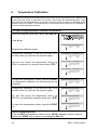
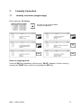
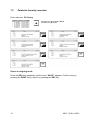
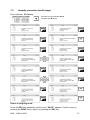
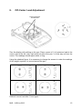
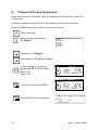
Download MLS...N Version 1.2
Transcript
KERN & Sohn GmbH Ziegelei 1 D-72336 Balingen-Frommern E-Mail: [email protected] GB Service Manual Electronic Moisture Analyzer Tel: 0049-[0]7433- 9933-0 Fax: 0049-[0]7433-9933-149 Internet: www.kern-sohn.com Page 2 KERN MLS 50-3…N Version 1.2 10/2008 
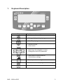
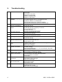
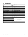
CONTENTS 1. 2. 3. 4. Keyboard Description .......................................................................................... 3 Troubleshooting................................................................................................... 4 Error Messages ................................................................................................... 5 Factory Menu (service menu).............................................................................. 6 4.1 How to enter the service menu..................................................................... 6 4.2 Description of factory parameters................................................................. 7 5. Factory Calibration .............................................................................................. 9 6. Temperature Calibration.................................................................................... 10 7. Linearity Correction ........................................................................................... 11 7.1 Linearity correction (single-stage) .............................................................. 11 7.2 Parabolic linearity correction ...................................................................... 12 7.3 Linearity correction (multi-stage) ................................................................ 13 7.4 Changing linearity factors........................................................................... 14 8. Off-Center Load Adjustment.............................................................................. 15 9. Printout of Factory Parameters.......................................................................... 16 2 MLS…N-SH-e-0812 1. Keyboard Description Key MLS…N-SH-e-0812 Function • Switch machine on/off • Change display during drying process • Start/Stop drying • • Cancel an entry Leave menu • • Arrow keys for navigation in menu Change the value of a parameter • • Data export to external device Confirm/save settings • Tara key scales zero digits • Invoke user menu (drying parameter setting) • Invoke user menu 3 2. Troubleshooting 1 Unit does not turn on 2 Balance is weighing but is unstable 3 No zero point after turning on the balance Balance shows wrong weight 4 5 Off center load error 6 Intense creeping (drift) 7 Linearity error 9 No communication between balance and PC 10 Time and date does not work 11 Display shows program number, no function 12 Outside maximum range 13 Balance works OK but drying is not correct 14 Temperature of chamber is incorrect 15 Heating lamps will not turn on at any time 16 Lamps will not turn off 4 Check mains cable Check fuses Check cable connections Problem on power board Problem on display board Problem on main board Mechanical damage Pan rubbing against case or not installed correctly Air drafts or vibration or unstable table Not good parameters for the working conditions Dirt inside the measurement system or inside the coil Pan needs to zero Mechanical damage Wrong calibration Mechanical damage to weighing mechanism Pan not installed correctly Off center load error Dirt inside the measurement system Check if the horizontal stat is being kept mechanical damage Mechanical damage Dirt inside the measurement system Linearity correction Mechanical damage Wrong parameter Check connection RS-232 to PC Wrong interface cable Check voltage TTL 2 Hz (0/+5V DC on measuring point SQW Problem on main board Batteries are damaged Quartz does not work Processor damage Check tension RST (reset) “1” +5V and exchange main board when RST does not work Mechanical damage Check voltage on measuring resistor Check parameters and mode selected Check samples are not hitting the temp. sensor Check temperature of chamber Check lamps Recalibrate temperature sensor Temperature sensor damaged Lamp circuits damaged Check lamps Check wiring of lamps Temperature sensor Damaged temp. sensor Recalibrate temp. sensor Lamp control circuits damaged MLS…N-SH-e-0812 3. Error Messages Fault messages Error of control sum Error A/D Overcrossed range Overcrossed range A/D Null A/D Full Tare/zero above the range Tare above the range Result > 10% Max Result > 4% Max Difference > 1% Max Sample mass < 20 mg Sample mass above the range Above the range Faulty value Incorrect password Error of notice Parity error Table error Suspended transmission CTS Suspended transmission XOFF Incorrect date Overcrossed time MLS…N-SH-e-0812 Error number 1.1 1.2 2.1 2.2 2.3 2.4 2.5 2.6 2.7 2.8 2.9 2.10 2.11 3.1 3.2 3.4 4.1 4.2 4.3 4.4 Description Error data transfer Error A/D converter Outside maximum range Outside maximum range Error A/D converter Error A/D converter Outside of weighing range Outside of taring range Result > 10 % Load on weighing plate too heavy Difference between cal. weight stored/current cal. weight > 1% Sample < 20 mg Sample out of set range Value of parameter outside Value of parameter outside Wrong password Error data transfer 4.5 5.1 6.1 Wrong data Timeout 5 4. Factory Menu (service menu) Contents of the factory menu are parameters needed to start, settings and regulations. 4.1 How to enter the service menu Open the housing and set jumper „JP1“ on main board 172xxx.PCB to access the service menu. Plug the balance into the power outlet and enter service menu. 6 MLS…N-SH-e-0812 4.2 Description of factory parameters Press the ON/OFF key (main switch) to turn on the balance Enter main menu Set index next to parameter P0 Factory Enter submenu P0 Factory Parameter Parameter name number Factory deff P0 01 P0 04 P0 05 P0 06 Balance Id Full scale (scale capacity) Div Ext. cal. mass Autozero range P0 07 Autozero delay P0 08 Stable range P0 09 Stable speed P0 10 Filter range P0 11 P0 12 P0 13 Show A/D div Show A/D T1 Show A/D T2 P0 14 Factory cal. P0 15 Factory T cal. P0 16 Linear. corr. P0 02 P0 03 MLS…N-SH-e-0812 Description Delete all settings in balance and load program primal settings » Factory setting (Reset) / PLEASE NOTICE you have to set all parameters new!!! Change factory number (serial number) Scale capacity (max) = weighing range +9 divisions: e.g. max range 50,09g Reading precision (resolution), e.g. 0.001 Value of external calibration weight [g], e.g. 50.0g Range of autozero function (possibility to change value from 0.1d to 10.0d) Normal 12= 3.0 d Time of autozero (possibility to change value from 0.2s to 3.0s) Normal 6= 2.0 s Stable range of measuring results (possibility to change value from 0.1d to 10.0d) Normal 11= 2.0 d Time to define stable measuring results (possibility to change value from 0.2s to 3.0s) Normal 6= 2.0 s Digital filter (possibility to change value from 1d to 10000d) Normal 5 – 20 d Value of A/D converter (of the load) A/D value of temperature sensor in the coil A/D value of temperature sensor in the drying chamber Starts factory calibration with external calibration weight Starts calibration of the temperature sensor inside the drying chamber Starts linearity procedure with external weights. You can inscribe max. 16 points of linearity. 7 P0 17 Temp. corr. P0 P0 P0 P0 P0 P0 P0 P0 P0 18 19 20 21 22 23 24 25 26 Start div Cal. factor Start div f. Cal. factor f. T. max Start T Factor T Start f. T Factor f. T P0 P0 P0 P0 P0 27 28 29 30 31 1’st point T Start T 2 Factor T 2 Start f.T2 Factor f. T 2 P0 P0 P0 P0 32 33 34 35 2’nd point T Temp. Z factor Temp. S factor Lin. points Lin. value 1 Lin. factor 1 Lin. value 2 Lin. factor 2 Lin. value 3 Lin. factor 3 . . . . Lin. value 15 Lin. factor 15 Lin. value 16 Lin. factor 16 Lin. factor A Lin. factor B Up/Down par. . . . . P0 P0 P0 P0 P0 P0 P0 64 65 66 67 68 69 70 P0 71 Stack info. P0 72 Bootloader 8 Starts temp. compensation in a room with regulated temperature (range ± 1°C). Correction is done in temp. 18°C up to 28°C. The parameters/values are stored after doing temperature compensation (parameters P0 27, P0 28). Preload (with pan) - balance find it automatically Calibration factor during factory calibration Preload after correction Not documented Not documented Not documented The factor during the temperature compensation Not documented The factor during temperature compensation after filtering First temperature correction set by 18°C Not documented Factor during temperature compensation 2’nd point Not documented The factor during temperature compensation after filtering 2’nd temperature point Second temperature correction set by 28°C Temperature compensation factor of zero Temperature compensation factor of sensitivity Those parameters are stored after doing linearity correction. These parameters (the stored values) can be changed manually (max. 16 points). Here you can change the linearity factor manually also without doing the linearity correction by using external weights. Parabolic linearity factor Parabolic linearity factor Printout of factory parameters, printout of moisture analyzer parameters or receipt of moisture analyzer parameters Information about the stored settings when the moisture analyzer will be started Select this parameter for software download / update MLS…N-SH-e-0812 P0 73 Fat perc. fun P0 74 Heater type P0 75 Cor, factor T 5. Function of large content in user menu 0= disabled (function not available in user menu) 1= enabled (function available in user menu) Type of heating element in moisture analyzer: 0= Halogen 1= IR Service parameter for characteristic of drying chamber thermometer Factory Calibration Enter submenu P0 Factory and press key to start factory calibration P0 14 Return to weighing mode: Press the ESC-key repeatedly until the query ”SAVE?“ appears. Confirm query by pressing the PRINT-key or reject it by pressing the ESC-key. MLS…N-SH-e-0812 9 6. Temperature Calibration We recommend checking the temperature value of the device from time to time. Before you do this, allow the device to cool down for at least 3 hours after the last heating phase. Push the probe into the designated hole in the disk. Push the probe as closely as possible to the thermal sensor of the MLS. The temperature is measured at two points and it is possible to correct it at both temperature points. Procedure using temperature calibration set MLB-A11 Select by using the arrow keys (Ð Ï) „04 Temp.cal“ 29.12.04 Setup 29.01.08 Setup Press Î key Temperature calibration 1 point 14:59 Temperature calibration starts. Temperature calibration of first point will take 14.59 min after which you will hear an acoustic signal. Now you can correct the temperature value (e.g. 25/24), as required, by using the arrow keys (Ð Ï). 29.01.08 Setup Temperature calibration 1 point 00:00 29.01.08 Setup Temperature calibration Set temp. value [°C] 25 29.01.08 Setup Temperature calibration Set temp. value [°C] 24 To import the temperature values, press the PRINTkey; temperature calibration for the second point will be started. Temperature calibration of first point will take 14.59 min after which you will hear an acoustic signal. You can now correct the temperature value (e.g. 120/122), as required by using the arrow keys (Ð Ï). To import the temperature values, press the PRINTkey. 29.01.08 Setup Temperature calibration 2 point 14:59 29.01.08 Setup Temperature calibration 2 point 00:00 29.01.08 Setup Temperature calibration Set temp. value [°C] 120 29.01.08 Setup Temperature calibration Set temp. value [°C] 122 Return to weighing mode: Press the ESC-key repeatedly until the query ”SAVE?“ appears. Confirm query by pressing the PRINT-key or reject it by pressing the ESC-key. 10 MLS…N-SH-e-0812 7. Linearity Correction 7.1 Linearity correction (single-stage) Enter submenu P0 Factory Set index next to parameter P0 16 and press the Î button Return to weighing mode: Press the ESC-key repeatedly until the query ”SAVE?“ appears. Confirm query by pressing the PRINT-key or reject it by pressing the ESC-key. MLS…N-SH-e-0812 11 7.2 Parabolic linearity correction Enter submenu P0 Factory Set index next to parameter P0 16 and press the Î button Return to weighing mode: Press the ESC-key repeatedly until the query ”SAVE?“ appears. Confirm query by pressing the PRINT-key or reject it by pressing the ESC-key. 12 MLS…N-SH-e-0812 7.3 Linearity correction (multi-stage) Enter submenu P0 Factory Set index next to parameter P0 16 and press the Î button Return to weighing mode: Press the ESC-key repeatedly until the query ”SAVE?“ appears. Confirm query by pressing the PRINT-key or reject it by pressing the ESC-key. MLS…N-SH-e-0812 13 7.4 Changing linearity factors 1. After come back to weighing mode do calibration. 2. Check balance readings in all measuring points. 3. In case of differences make a note. 4. If there is a positive difference you should add this difference to the factor. If there is a negative difference you should subtract this difference to the factor. Æ changing in the factory menu (service menu), parameters P0 37 until P0 67 E.g.: weight mass 40g Æ reading 40.007 stored linearity factor at 40g Æ 0.001 input new linearity factor at 40g Æ 0.008 weight mass 40g Æ reading 39.995 stored linearity factor at 40g Æ 0.001 input new linearity factor at 40g Æ - 0.004 5. After inscribing correction you should do calibration again. 6. Check balance readings in all measuring points. 7. Repeat this process until you will get the expected results. 14 MLS…N-SH-e-0812 8. Off-Center Load Adjustment Scews to adjust the off-center load Zero the display with nothing on the pan. Place a mass of ⅓ of maximum load at the centre, than at the left, rear, right and front side of the pan, ½ of the way out from the centre. The readings should agree within ± 5mg. Using the attached figure. It is necessary to change the screws to make the readings of the weight equal as it is moved around the pan. Recheck corner load after 1 hour again. MLS…N-SH-e-0812 15 9. Printout of Factory Parameters Open the housing and set jumper „JP1“ on main board 172xxx.PCB to access the service menu. Connect a standard printer to RS 232 data interface of the moisture analyzer. Press the ON/OFF key (main switch) to turn on the balance. Enter main menu Set index next to parameter P7 Globals 29.12.04 P1 C alibration P2 GLP P3 Date/Time P4 Redout P5 RS-232 P6 Printouts P7 Globals Setup Enter menu P7 Globals Enter submenu P7 09 Par. printout To get a printout of the factory parameters P0 01 to P0 75 set Start= 0.01 Stop= 0.75 Confirm your setup with PRINT Press PRINT to start the printout 16 MLS…N-SH-e-0812