1
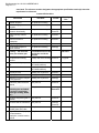
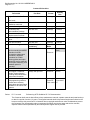
Page 1 of 17
Co
orporate Finance Department
Materials
M
Managem
ment Division
631-2014
4 ADDEN DUM 3
SUPPLY AN
ND DELIVERY
Y OF HEAVY
Y-DUTY 40 FT
T. LOW-FLOOR TRANSIT
T
BUSES
ISSUED:
Au
ugust 13, 2014
BY:
Glen Kuhl
TELEPHONE NO. (204) 986--5801
URGEN
NT
PLEASE
E FORWAR
RD THIS DO
OCUMENT
T TO
WHOEV
VER IS IN POSSESSIO
P
ON OF THE
E BID
OPPORT
TUNITY
THIS ADDE
ENDUM SHA
ALL BE INCORPORATED
INTO THE B
BID OPPORT
TUNITY AND
D SHALL
FORM A PA
ART OF THE
E CONTRACT
T
DOCUMEN
NTS
Template Version: A201311229
Pleas
se note the fo
ollowing and
d attached ch
hanges, corre
ections, add itions, deletiions, informa
ation and/or instructions
s
in con
nnection with the Bid Op
pportunity, an
nd be govern
ned accordin
ngly. Failure
e to acknowledge receiptt of this
Addendum in Parragraph 9 of Form A: Bid may render your Bid no
on-responsiv
ve.
PAR
RT B – BIDDING PRO
OCEDURES
S
Revisse: B2.1 to re
ead:
Add:
The Subm
mission Dea
adline is 4:0
00 p.m. Winnipeg time,, August 20, 2014.
B16
ELIGIBILITY
E
B16.1
Various
V
organ
nizations provided investiga
ative servicess with respectt to this Bid
Opportunity
y. In the City’’s opinion, thi s relationship
p or associatio
on does not ccreate a
conflict of in
nterest or will not likely cre
eate a perception of conflicct of interest b
because of
this disclosure. The organizations are
re:
(i)
(
New Flyer
F
Industrie
es Ltd.
(ii)
(
Nova Bus
PAR
RT D – SUP
PPLEMENT
TAL COND
DITIONS
Revisse: D2.1 to re
ead:
The Work to be done un
nder the Contrract shall con
nsist of the supply and delivvery of low
floor transitt diesel buses
s from the datte of award to
o October 30thh, 2015, with the option
of four (4) mutually agrreed upon on
ne (1) year e
extensions.
Revisse: D2.1 (a) to
o read:
Each (4) fo
our year extension will be
e for approxim
mately thirty-th
hree (33) low floor transit
diesel buse
es.
Remove: From D2
2.5:
In-process
s drawings
Revisse: D2.5 to re
ead:
30 days
s prior to pilo
ot bus Scale
e drawings
1
Refere
encing APTA Guideline SP
P 2.3 Contractt Deliverabless:
Contract delive
erables assoc
ciated with this Contractt are set forth
h in the table
e below, alon
ng with otherr
perrtinent inform
mation. Conttract delivera
ables shall b e submitted in accordan
nce with E1. D
Due dates
sho
own note the
e last acceptable date forr receipt of C
Contract deliv
verables. Alll documents
s must be
acc
ceptable to th
he City. All parts
p
and serrvice correcttions must b
be made, on tthe master electronic
cop
py, within 30
0 days of notice. The elec
ctronic corre
ections must be followed by all hardc
copy updates
s
witthin 90 days of notice. Th
he City will consider early
y receipt of C
Contract deliverables on
n a case-by-
Bid Opportunity No. 631-2014 ADDENDUM 3
Page 2 of 17
case basis. The reference section designates the appropriate specification section(s) where the
requirement is referenced.
Contract Deliverables
Deliverable
Due Date
Quantity
Due
Format
Material samples
Pre-production meeting
Undercoating system
program
Pre-production meeting
Electronic
1
Technical review of
electronic functionality
Pre-production meeting
Hardcopy
Electronic
1
1
Interior security camera
layout
Pre-production meeting
Electronic
1
Technical review of
powerplant
Pre-production meeting
Electronic
1
Engineering support
Pre-production meeting
Contracts
1
List of OEM component
repair manuals
Pre-production Meeting
Hardcopy
1
Training – 100 instructor
hours per contract year
Accumulated hours to be
used by the end of the
contract
100 hours
Pre-production meeting
minutes
15 days after each meeting Electronic
2 originals
Recommended spare parts
list
Provided 10 business after Electronic
the Pilot Bus delivery
1
Part number index
Provided 10 business after Electronic
the Pilot Bus delivery
1
Current price list
30 days prior to pilot bus
Electronic
1
Striping layout
30 days prior to pilot bus
Hardcopy
1
Resolution of issues “subject 30 days prior to pilot bus
to City approval”
Hardcopy
1
Preliminary Parts & Service
Manual
Electronic
1
All available OEM manuals With pilot bus
(including but not limited
to engine, transmission,
passenger seating, HVAC,
etc.)
Hardcopy
Electronic
3
1
Complete Engineering Bill of With pilot bus
Material.
Electronic
1
Electrical and air schematics With pilot bus
Hardcopy
Electronic
3
1
Glazing drawings/spec for all With pilot bus
window glass on the bus
Electronic
1
Current index file displaying With pilot bus
all Part Numbers,
description, manual location,
Build #.
Electronic
1
With pilot bus
1
Bid Opportunity No. 631-2014 ADDENDUM 3
Page 3 of 17
Contract Deliverables
Deliverable
Due Date
Quantity
Due
Format
Engine Emissions Certificate With pilot bus
—
NOx levels
Hardcopy
1
List of serialized units
installed on each bus
With each bus
Electronic
1 per bus
QA manufacturing certificate With each bus
Hardcopy
1 per bus
Pre-Delivery Bus
Documentation Package
With each bus
Hardcopy
1 per bus
Motor Vehicle Pollution
Requirements Certificate
With each bus
Hardcopy
1
Operator’s log and incident
report
With each bus
Hardcopy
1 per bus
Title documentation
With each bus
Hardcopy
1 per bus
As-built drawings
Within 60 days after final Electronic
bus delivery
Media
Final Manuals - current
90 days after pilot bus
service manual(s) and OEM
manuals to include
preventative maintenance
procedures, diagnostic
procedures or troubleshooting guides and major
component service manuals,
current parts manual(s), and
standard operator’s
manual(s)
1
Electronic
7 per build
(total)
1
Hardcopy
All electronic software
To be held in escrow
Electronic
1 Each
Bus Supplier / OEM Part
Number Cross-reference,
including OEM identification
and contact information
90 days after pilot bus
Electronic
1 Each
All full versions of diagnostic 90 days after pilot bus
and programming software,
licenses and necessary
patch cables and associated
hardware for all vehicle subsystems
Revise:
D17.1 to read:
Hardcopy
1
Electronic
10 per build
Patch cable 10
Referencing APTA Guideline SP 7.2 Documentation:
The Contractor shall exert its best efforts to keep maintenance manuals, operator manuals and parts books up
to date for a period of twelve (12) years. The supplied manuals shall incorporate all equipment ordered on the
buses covered by this procurement. In instances where copyright restrictions or other considerations prevent
the Contractor from incorporating major components information into the bus parts and service manuals,
separate manual sets as published by the subcomponent supplier will be provided.
Bid Opportunity No. 631-2014 ADDENDUM 3
Page 4 of 17
Revise:
D19.1 (a) to read: Referencing APTA Guideline WR 1.1.2 Complete Bus:
The complete bus (excluding City of Winnipeg installed items), propulsion system, components, all subsystems
and body and chassis structure are warranted to be free from defects and related defects for one year or 80,000
kilometres, whichever comes first, beginning on the date of revenue service but not longer than 15 days after
acceptance under “Inspection, Testing and Acceptance.” The warranty is based on regular operation of the bus
under the operating conditions prevailing in the City’s locale.
In the event of “coach down” for repairs, in excess of 14 days, the warranty date shall be adjusted to
compensate for the days the coach was not in revenue service. In the event of Coach Down for
warranty repairs, in excess of 30 days, Liquidated Damages as referenced in D12 shall be incurred.
Revise:
D19.1 (d) to read: Referencing APTA Guideline WR1.1.5 Emission Control System (ECS):
The Contractor warrants the emission control system for five years or 160,000 kilometres, whichever comes
first. The ECS shall include, but is not limited to, the following components:
Revise:
•
complete exhaust system, including catalytic converter (if required)
•
after-treatment device
•
components identified as emission control devices
D19.1 (f) to read: Referencing APTA Guideline WR 1.1.7 Extended Warranty:
The City requires the following additional subsystems to be warranted to be free from Defects and Related
Defects for three years or 300,000 miles whichever comes first.
•
Revise:
Shock absorbers
D19.1 (i) to read: Referencing APTA Guideline WR 1.3.1 Pass-Through Warranty
The Contractor shall not transfer warranty responsibility to any sub-Supplier, or to others.
The Contractor shall be solely responsible for the administration of the warranty as specified with
exception of the following; engine, transmission, HVAC, destination signs and batteries.
Clarification of D19.1 (n): The intention is that Winnipeg Transit will handle normal warranty defects with complete
reimbursement per warranty specifications.
Revise: D19.2 to read:
Further to C11, the City and the Contractor may negotiate an agreement for the City’s own forces to perform
warranty repair work under the following conditions:
(a)
monthly warranty repairs beyond 100 hours shall be charged at overtime rates;
(b)
the Contractor will either supply all materials necessary to perform the warranty repair or reimburse to the
City, the full costs of parts and materials supplied by the City within 60 Calendar Days of use;
(c)
labour rates for warranty repair work performed by City forces during normal working hours will be $ 95.00
per person hour, the overtime labour rate will be $ 120.00 per person hour.
Bid Opportunity No. 631-2014 ADDENDUM 3
Page 5 of 17
PART E – SPECIFICATIONS
Revise:
E2.17 to read: Referencing APTA Guideline TS 5.8 Noise:
Interior Noise
The combination of inner and outer panels and any material used between them shall provide sufficient sound
insulation so that a sound source with a level of 80 dBA measured at the outside skin of the bus shall have a
sound level of 65 dBA or less at any point inside the bus. These conditions shall prevail with all openings,
including doors and windows, closed and with the engine and accessories switched off.
The bus-generated noise level experienced by a passenger at any seat location in the bus shall not exceed 80
dBA. The operator area shall not experience a noise level of more than 75 dBA.
Exterior Noise
Airborne noise generated by the bus and measured from either side shall not exceed 80 dBA under full power
acceleration when operated 0 to 55 km/h at curb weight. The maximum noise level generated by the bus pulling
away from a stop at full power shall not exceed 83 dBA. The bus-generated noise at curb idle shall not exceed
65 dBA. If the noise contains an audible discrete frequency, a penalty of 5 dBA shall be added to the sound
level measured. The Contractor shall comply with the exterior noise requirements defined in local laws and
ordinances identified by the City and SAE J366.
Revise:
E2.24 to read: Referencing APTA Guideline TS 6.4 Step Height
The step height shall not exceed 14.6 inches at either doorway without kneeling. A maximum of two steps is
allowed to accommodate a raised aisle floor in the rear of the bus.
Revise:
E2.29 to read: Referencing APTA Guideline TS 6.8 Floor Height:
Height of the step above the street shall be no more than 14.6 in. measured at the centerline of the front and
rear doorway. The floor may be inclined along the longitudinal axis of the bus, and the incline shall not exceed
3.5 degrees off the horizontal except locally at the doors where 2 degree slope toward the door is allowed. All
floor measurements shall be with the bus at the design running height and on a level surface and with the
standard installed tires. A maximum of two steps is allowed to accommodate a raised aisle floor in the rear of
the bus.
Revise:
E2.31 to read: Referencing APTA Guideline TS 6.10 Aisle Width:
The minimum clear aisle width between pairs of transverse seats with all attached hardware shall be at least 22
inches.
The aisle width between the front wheelhouses shall be at least 35 inches, and the entire area between the
front wheelhouses shall be available for passengers and mobility aid devices.
Revise:
E2.43 to read: Referencing APTA Guideline TS 10.1 Engine Cooling:
A means of determining satisfactory engine coolant level shall be provided. A spring-loaded, push-button type
valve or lever shall be provided to safely release pressure or vacuum in the cooling system with both it and the
water filler no more than 60 inches above the ground. Both shall be accessible through the same access door.
The radiator shall be of durable, corrosion-resistant construction with removable tanks. The radiator or
coolant system drain shall be easily accessible from the engine compartment and equipped with a flat
Bid Opportunity No. 631-2014 ADDENDUM 3
Page 6 of 17
faced coupler manufactured by “Stucchi”. Stucchi coupler #800901001 and protective boot
#815100001.
Radiators with a fin density greater than 12 fins per inch or a louvered slit design shall not be used. No heatproducing components or climate control system components shall be mounted between the engine cooling air
intake aperture and the radiator. The radiator and charge air cooler shall be designed to withstand thermal
fatigue and vibration associated with the installed configuration. The radiator and charge air cooler cores shall
be easily cleaned (to include engine side core surface) with standard pressure-washing equipment or using high
volume, low pressure if water is used to clean the system.
Screen in Front of Radiator and Charge Air Cooler
For radiators with lower edge less than 36 inches to the ground
The radiator and air cooler shall be protected by an aluminum perforated screen with staggered ¼”
holes. The screen shall be capable of maintaining sufficient air flow for the cooling requirements.
Standard Requirement for Coolant Filtration
The engine cooling system shall be equipped with a properly sized water filter with a spin-on element and an
automatic system for releasing supplemental coolant additives as needed to replenish and maintain protection
properties. When replacing the water filter, only the water in the filter will be lost.
Cooling Fan Control and Drive Design
Control and drive of the radiator and charge air cooler fan(s) shall be an electric EMP or Modine system.
The cooler fans shall have integrated controllers. Cooler fans shall be capable of automated reverse operations
for periodic self-cleaning of the radiator and charge air cooler. Radiator cooling and Charge Air cooling must
operate independently.
Clarification of E2.49 to: Oil Pressure and Coolant gauges can be mechanical gauges, electrical gauges or digital display.
Revise:
E2.54 to read: Referencing APTA Guideline TS 15. Radiator:
Radiator piping, within 36 inches of the ground, shall be stainless steel or brass tubing, and if practicable, hoses
shall be eliminated. Necessary hoses shall be impervious to all bus fluids. All hoses shall be secured with
stainless steel clamps that provide a complete 360-degree seal. The clamps shall maintain a constant tension
at all times, expanding and contracting with the hose in response to temperature changes and aging of the hose
material.
Revise:
E2.59 to read: Referencing APTA Guideline TS 17.2.1 Design and Construction, Diesel:
Fuel Tank(s)
The fuel tank(s) shall be made of high-density cross-linked polyethylene plastic material.
Installation
The fuel tank(s) shall be securely mounted to the bus to prevent movement during bus maneuvers.
The fuel tank(s) shall be equipped with an external, hex head, drain plug. It shall be at least a ⅜-inch size and
shall be located at the lowest point of the tank(s). The fuel tank(s) shall have an inspection plate or easily
removable filler neck to permit cleaning and inspection of the tank(s) without removal from the bus. The tank(s)
shall be baffled internally to prevent fuel-sloshing noise regardless of fill level. The baffles or fuel pickup location
shall assure continuous full power operation on a 6 percent upgrade for 15 minutes starting with no more than
Bid Opportunity No. 631-2014 ADDENDUM 3
Page 7 of 17
95 litres of fuel over the unusable amount in the tank(s). The bus shall operate at idle on a 6 percent downgrade
for 30 minutes starting with no more than 38 litres of fuel over the unusable amount in the tank(s).
The materials used in mounting shall withstand the adverse effects of road salts, fuel oils, and accumulation of
ice and snow for the life of the bus.
Labeling
The capacity, date of manufacture, manufacturer name, location of manufacture, and certification of compliance
to Federal Motor Carrier Safety Regulation shall be permanently marked on the fuel tank(s). The markings shall
be readily visible and shall not be covered with an undercoating material.
Fuel Filler
The fuel filler shall be located 7 to 33 feet behind the centerline of the front door on the curb side of the bus. The
filler cap shall be retained to prevent loss and shall be recessed into the body so that spilled fuel will not run
onto the outside surface of the bus.
The fuel lines forward of the engine bulkhead shall be in conformance to SAE Standards.
Dry-break fuel filler
The fuel filler shall accommodate a nozzle that forms a locked and sealed connection during the refueling
process to eliminate spills. Fuel shall not be allowed to flow into the tank unless the nozzle has been properly
coupled, locked and sealed to the filler. With the nozzle open, fuel shall enter the tank at a fill rate of not less
than 150 litres per minute of foam-free fuel without causing the nozzle to shut off before the tank is full. The
nozzle shall automatically shut off when the tank is essentially full. Once disconnected, fuel shall not be allowed
to flow through the nozzle at any time. Any pressure over 3 psi shall be relieved from the fuel tank
automatically. An audible signal shall indicate when the tank is essentially full. The dry break system shall be
compatible with the City’s system. The fuel filler cap shall be hinged.
Revise:
E2.69 to read: Referencing APTA Guideline TS 22.2 Crashworthiness:
The bus body and roof structure shall withstand a static load equal to 150 percent of the curb weight evenly
distributed on the roof with no more than a 6 in. reduction in any interior dimension. Windows shall remain in
place and shall not open under such a load. These requirements must be met without the roof-mounted
equipment installed.
The bus shall withstand a 40 km/h impact by a 1800 kg automobile at any side, excluding doorways, along
either side of the bus with no more than 3 in. of permanent structural deformation at seated passenger hip
height. This impact shall not result in sharp edges or protrusions in the bus interior.
Exterior panels below 35 inches from ground level shall withstand a static load of 907 kg applied perpendicular
to the bus by a pad no larger than 5 square inches. This load shall not result in deformation that prevents
installation of new exterior panels to restore the original appearance of the bus.
Revise:
E2.70 to read: Referencing APTA Guideline TS 23. Corrosion:
The bus flooring, sides, roof, under-structure and axle suspension components shall be designed to
resist corrosion or deterioration from atmospheric conditions and all de-icing materials for a period of
18 years or 1.2 million kilometres, whichever comes first. It shall maintain structural integrity and nearly
maintain original appearance throughout its service life.
All materials that are not inherently corrosion resistant shall be protected with corrosion-resistant coatings. All
joints and connections of dissimilar metals shall be corrosion resistant and shall be protected from galvanic
corrosion. Representative samples of all materials and connections shall withstand a two-week (336-hour) salt
Bid Opportunity No. 631-2014 ADDENDUM 3
Page 8 of 17
spray test in accordance with ASTM Procedure B-117 with no structural detrimental effects to normally visible
surfaces and no weight loss of over 1 percent.
Corrosion Resistance Requirements for Exposed and Interior Surfaces of Tubing Throughout Entire
Vehicle
All exposed surfaces of tubing and other enclosed members shall be corrosion resistant through
application of a corrosion protection system. All interior surfaces, excluding corrosion resistant
stainless, shall be corrosion resistant through application of a corrosion protection system.
Revise:
E2.116 to read: Referencing APTA Guideline TS 37.3 Air Lines and Fittings:
Air lines, except necessary flexible lines, shall conform to the installation and material requirements of SAE
Standard J1149 for copper tubing with standard, brass, flared or ball sleeve fittings, or SAE Standard J844 for
nylon tubing if not subject to temperatures over 200 oF. The air on the delivery side of the compressor where it
enters nylon housing shall not be above the maximum limits as stated in SAE J844. Nylon tubing shall be
installed in accordance with the following color-coding standards:
•
Green: Indicates primary brakes and supply.
•
Red: Indicates secondary brakes.
•
Brown: Indicates parking brake
•
Yellow: Indicates compressor governor signal.
•
Black: Indicates accessories.
Line supports shall prevent movement, flexing, tension, strain, chafing and vibration. Copper lines shall be
supported to prevent the lines from touching one another or any component of the bus. To the extent
practicable and before installation, the lines shall be pre-bent on a fixture that prevents tube flattening or
excessive local strain. Copper lines shall be bent only once at any point, including pre-bending and installation.
Rigid lines shall be supported at no more than 5-ft intervals. Nylon lines may be grouped and shall be supported
at 30 in. intervals or less or as approved by property inspector (agency).
The compressor discharge line between powerplant and body-mounted equipment shall be flexible Teflon hose
with a braided stainless steel jacket. All lines necessary to maintain system reliability shall be flexible Teflon
hose with a braided stainless steel jacket. End fittings shall be standard SAE or JIC brass or steel, flanged,
swivel-type fittings. Flexible hoses shall be as short as practicable and individually supported. They shall not
touch one another or any part of the bus except for the supporting grommets. Flexible lines shall be supported
at 2-ft intervals or less or as approved by property inspector (agency).
Air lines shall be clean before installation and shall be installed to minimize air leaks. All air lines shall be routed
to prevent water traps to the extent possible. Grommets or insulated clamps shall protect the air lines at all
points where they pass through understructure components.
Revise:
E2.136 to read: Referencing APTA Guideline TS 40.5 Electrical Compartments:
All relays, controllers, flashers, circuit breakers and other electrical components shall be mounted in easily
accessible electrical compartments. All compartments exposed to the outside environment shall be corrosionresistant and sealed. The components and their functions in each electrical compartment shall be identified and
their location permanently recorded on a drawing attached to the inside of the access panel or door when
possible. The drawing shall be protected from oil, grease, fuel and abrasion. The front compartment shall be
completely serviceable from the operator’s seat, vestibule or from the outside. “Rear start and run” controls shall
be mounted in an accessible location in the engine compartment and shall be protected from the environment.
The PLC shall be initialized from the rear engine compartment when the following conditions are met;
Bid Opportunity No. 631-2014 ADDENDUM 3
Page 9 of 17
•
•
•
Revise:
rear run switch is in the rear run position
start push button held for 5 seconds
audio/visual warning activated; (i.e. back-up lights/amber light flashing)
E2.145 to read: Referencing APTA Guideline TS 42.1 General:
The primary purpose of the multiplexing system is control of components necessary to operate the vehicle. This
is accomplished by processing information from input devices and controlling output devices through the use of
an internal logic program.
Versatility and future expansion shall be provided for by expandable system architecture. The multiplex system
shall be capable of accepting new inputs and outputs through the addition of new modules and/or the utilization
of existing spare inputs and outputs. All like components in the multiplex system shall be modular and
interchangeable with self-diagnostic capabilities. The modules shall be easily accessible for troubleshooting
electrical failures and performing system maintenance. Multiplex input/output modules shall use solid-state
devices to provide extended service life and individual circuit protection.
All modules shall be repairable at the component level.
Ten percent of the total number of inputs and outputs, or at least one each for each voltage type utilized (0V,
12V, 24V), at each module location shall be designated as spares.
The Contractor must supply 4 - notebook computers per bus build to be used for diagnostic and
programming functions. The computers must be equipped with the latest version of the Windows
operating system, colour screens, integral pointing devices, CD Rom Drives, floppy drive, the largest
capacity hard drive available for the computer and twice the minimum RAM memory required to run all
applicable software.
The computers shall be equipped with the latest versions of all software required for diagnostics and
programming of the Engine, Transmission, PLC, ABS, Electronic Signs, and all other Electronic
equipment included in the vehicle. All software must be installed and functional.
The computers shall include all peripheral communication hardware, such as PIC’s, links and adapters
used in downloading and programming of the equipment. Data Link connectors shall be provided 10
connectors per bus build to function with computer equipment and all applicable software provided.
Cigarette type plug-in to be provided at Lap Top diagnostic plug locations for Lap Top operation.
The City of Winnipeg shall have final approval of the hardware and software to be supplied. Computers
supplied under contract must be available for testing of all functions and data link connections during
pre-delivery inspections.
Revise: E2.163 to read: Referencing APTA Guideline TS 44.5 Normal Bus Operation Instrumentation and Controls:
The following list identifies bus controls used to operate the bus. These controls are either frequently used or
critical to the operation of the bus. They shall be located within easy reach of the operator. The operator shall
not be required to stand or turn to view or actuate these controls unless specified otherwise.
Systems or components monitored by onboard diagnostics system shall be displayed in clear view of the
operator and provide visual and/or audible indicators. The intensity of indicators shall permit easy determination
of on/off status in bright sunlight but shall not cause a distraction or visibility problem at night. All indicators shall
be illuminated using backlighting.
The indicator panel shall be located in Area 1 or Area 5, within easy view of the operator instrument panel. All
indicators shall have a method of momentarily testing their operation. The audible alarm shall be tamperresistant and shall have an outlet level between 80 and 83 dBA when measured at the location of the operator’s
ear.
Bid Opportunity No. 631-2014 ADDENDUM 3
Page 10 of 17
On-board displays visible to the operator shall be limited to indicating the status of those functions described
herein that are necessary for the operation of the bus. All other indicators needed for diagnostics and their
related interface hardware shall be concealed and protected from unauthorized access. Table 6 represents
instruments and alarms. The intent of the overall physical layout of the indicators shall be in a logical grouping of
systems and severity nature of the fault.
Consideration shall be provided for future additions of spare indicators as the capability of onboard diagnostic
systems improves. Blank spaces shall contain LEDs.
Transit Bus Instruments and Alarms
Device
Description
Location
Function
Visual/ Audible
Master run
switch
Rotary, fourposition detent
Master control for bus, off,
Side console day run, night run and
clearance ID lights
Engine start,
front
Approved
momentary switch
Side console
Engine start,
rear
Approved
momentary switch
Engine
Activates engine starter
compartment motor
Engine run, rear
Three-position
toggle switch
Permits running engine
Engine
from rear start, normal front Amber light
compartment
run position and off
Drive selector
Touch panel switch
Dash right
wing
HVAC
Switch or switches
to control HVAC
Permits selection of
passenger ventilation: off,
Side console
cool, heat, low fan, high fan
or full auto with on/off only
Operator’s
ventilation
Rotary, threeposition detent
Above Side
console or
Dash left
wing
Permits supplemental
ventilation: fan off, low or
high
Defroster fan
Rotary, fourposition detent
Dash left
wing
Permits defroster: fan off,
low, medium and high
Variable position
Dash left
wing
Adjusts defroster water flow
and temperature
Windshield
wiper
Variable rotary
position operating
each wiper
separately
Dash left
wing
Variable speed control of
left and right windshield
wipers
Windshield
washer
Push button
Dash left
wing
Activates windshield
washers
Defroster
temperature
Activates engine starter
motor
Provides selection of
propulsion: forward,
reverse and neutral
Gear selection
Bid Opportunity No. 631-2014 ADDENDUM 3
Page 11 of 17
Transit Bus Instruments and Alarms
Device
Description
Location
Function
Visual/ Audible
Provides adjustment for
light intensity in night run
position
Dash panel
lights
Rotary rheostat or
stepping switch
Dash left
wing
Interior lights
Two-position
switch
Selects mode of passenger
Side console compartment lighting: off,
on
Fast idle
Two-position switch Side console
Selects high idle speed of
engine
Side console
– within hand
Permits deploy and stow of Red light,
reach of door
front ramp
warning alarm
control
handle
Front door
ramp
Three-position
momentary switch
Front kneel
Side console
Three-position
– within hand Permits kneeling activation
momentary switch
reach of door and raise and normal at
with protective
control
front door remote location
guard
handle
Right remote
mirror
Permits two-axis
Four-position toggle
Side console adjustment of right exterior
type
mirror
Mirror heater
Temperature
activated
Amber
indicator. Ext
alarm and
Amber light
Permits heating of outside
mirrors when required
Permits open/close control
Passenger door Five-position handle Side console,
of front and rear passenger Red light
control
type detent
forward
doors
Rear door
override
Side console,
within hand
Allows operator to override
Two-position
reach of door activation of rear door
switch in
passenger tape switches
approved location control
handle
Engine
shutdown
override
Momentary switch
with protective
cover
Permits operator to
Side console override auto engine
shutdown
Two-position switch
Activates emergency
Hazard flashers with 50mm actuator Side console
flashers
lever
Mobile data
terminal
Mobile data
terminal coach
operator interface
panel
Above right
dash wing
Facilitates operator
interaction with
communication system and
master log-on
Two green
lights
LCD display
with visual
status and text
messages
Bid Opportunity No. 631-2014 ADDENDUM 3
Page 12 of 17
Transit Bus Instruments and Alarms
Device
Farebox
interface
Description
Farebox coach
operator interface
panel
Location
Function
Facilitates operator
Near farebox interaction with farebox
system
Visual/ Audible
LCD display
in approved
location
Facilitates operator
interaction with destination
sign system, manual entry
LCD display
Turn signals
Momentary push
button (two
required) raised
from other
switches
Left foot
panel
Activates left and right turn
signals
Two green
lights and
audible
indicator
PA manual
Momentary push
button
Left foot
panel
Permits operator to
manually activate public
address microphone
Microphone
Atlas Sound
gooseneck
assembly or GFI
(Genfare)
gooseneck
assembly
Left front
corner of the
operator’s
compartment.
Permits operator to make
announcements with both
hands on the wheel and
focusing on road conditions
High beam
Detent push button
Permits operator to toggle
Left foot floor between low and high
beam
Blue light
Parking brake
Pneumatic PPV
Below or on Permits operator to apply
Side console and release parking brake
Red light
Park brake
release
Pneumatic PPV
Below or on Permits operator to push
Side console and hold to release brakes
Park brake
alarm
Alarm
Under Dash
Remote engine
speed
Rotary rheostat
Permits technician to raise
Engine
and lower engine RPM
compartment
from engine compartment
Master brake
interlock
Toggle, with
protective guard
Overhead left
Permits operator override
Out of
to disable brake/throttle
operator’s
interlock
reach
Toggle switch
Overhead left
Out of
Permits operator override
operator’s
to disable door
reach
Destination sign Destination sign
interface
interface panel
Master door
Warns operator park brake
disabled when master
switch off
Buzzer
Bid Opportunity No. 631-2014 ADDENDUM 3
Page 13 of 17
Transit Bus Instruments and Alarms
Device
Description
Location
Function
Visual/ Audible
Warning
interlocks
deactivated
Red light and
Alarm
Dash panel
center
Illuminates to warn operator
Red light and
that interlocks have been
Alarm
deactivated.
Retarder
disable
Toggle switch
Within reach
of Operator
Permits operator override
to disable brake
retardation/regeneration
Auxiliary
power
12 volt power
receptacle
Approved
locations
Diagnostic Connector
Speedometer
Speedometer,
odometer, and
diagnostic
capability, 10
kilometres
increments, no
trip meter
Dash center
panel
Visual indication of speed
and distance traveled,
accumulated vehicle
kilometres, fault condition
display
Visual
Air pressure
gauge
Primary and
secondary,
5 psi increments
Dash center
panel
Visual indication of primary
and secondary air systems
Red light and
buzzer
Fire detection
Coach operator
display
Property
specific or
dash center
Indication of fire
detection activation by
zone/location
Buzzer and
red light
Door
obstruction
Sensing of door
obstruction
Dash center
Indication of rear door
sensitive edge activation
Red light and
Buzzer
Door ajar
Door not properly
closed
Property
specific or
dash center
Indication of rear door not
properly closed
Alarm and red
light
Low system air
pressure
Sensing low
primary and
secondary air tank
pressure
Dash center
Indication of low air system Buzzer and red
pressure
light
Engine coolant
indicator
Low coolant
indicator may be
Within
supplied as audible operator’s
alert and visual and sight
text message
Detects low coolant
condition
Amber light
Hot engine
indicator
Coolant
temperature
Within
indicator may be
operator’s
supplied as audible
sight
alert and visual and
text message
Detects hot engine
condition and initiates time
delay shutdown
Red light
Red light
Bid Opportunity No. 631-2014 ADDENDUM 3
Page 14 of 17
Transit Bus Instruments and Alarms
Device
Revise:
Description
Location
Function
Visual/ Audible
Low engine oil
pressure
indicator
Engine oil pressure
indicator may be
Within
supplied as audible operator’s
alert and visual and sight
text message
Detects low engine oil
pressure condition and
initiates time-delayed
shutdown
Red light
ABS indicator
Detects system
status
Dash center
Displays system failure
Amber light
ABS blink
code
Toggle switch
Inside front
sign above
operator
Retrieve ABS code
Charging
Detect charging
system indicator
system status
(12/24 V)
Dash center
Detects no charge
condition and optionally
detects battery high, low,
imbalance, no charge
condition
Red light
flashing or solid
based on
condition
Fuel tank level
Indicator light
Dash center
Indication of fuel tank
level/pressure, at less than
55 litres useable
Yellow
DEF gauge
Level Indicator
Center dash
Displays level of DEF tank
and indicates with warning
light when low
Red light
Active
regeneration
Detects Status
Dash center
Indication of electric
regeneration
Amber
Regeneration
Multi-Toggle
switch
Inside front
sign above
operator
Initialize, inhibit, normal
regeneration
Auxiliary
Heater
Toggle switch
Overhead
left Out of
operator’s
reach
Inhibit auxiliary heater
operation
Stop Request
Light
Indicator Light
Dash Centre
Passenger Stop Request
Red, 2 cm
E2.196 to read: Referencing APTA Guideline TS 50. Operator’s Side Window:
The operator’s side window shall be a fore and aft sliding type, requiring only the rear half of sash to
latch upon closing. The front sash shall open sufficiently to permit the seated operator to easily adjust
the street-side outside rear view mirror and shall have an interior handle only. When in an open
position, the window shall not rattle or close during braking. This window section shall slide in tracks
or channels designed to last the service life of the bus. The operator’s side window shall not be bonded
in place and shall be easily replaceable. The glazing material shall have a single-density tint.
Bid Opportunity No. 631-2014 ADDENDUM 3
Page 15 of 17
The operator’s side window shall include a “Rapid Replacement Glazing System” that permits the
removal and installation of each piece of glass in three (3) minutes or less. Glazing materials shall be
one quarter inch or six millimeter (1/4" or 6mm) nominal thickness laminated safety glass strictly
conforming to applicable sections of FMVSS 205 and ANSI Z26. 1 – 1997, Test Grouping 2 and the
Recommended Practices defined in SAE J673. The maximum permissible light transmittance of the fore
and aft sliding sections shall be 75% (Green) and the maximum permissible solar energy transmittance
shall be 68% as measured by ASTM-424.
The operator’s view, perpendicular through operator’s side window glazing, should extend a minimum of 33 in.
(840 mm) to the rear of the heel point on the accelerator, and in any case must accommodate a 95th percentile
male operator. The view through the glazing at the front of the assembly should begin not more than 26 in. (560
mm) above the operator’s floor to ensure visibility of an under-mounted convex mirror. Operator’s window
construction shall maximize ability for full opening of the window.
The operator’s side window glazing material shall have a ¼ in. nominal thickness laminated safety glass
conforming with the requirements of ANSI Z26.1-1996 Test Grouping 2 and the Recommended Practices
defined in SAE J673.
The design shall prevent sections from freezing closed in the winter.
Standard Operator’s Side Window, Traditional Frame
•
full slider
•
non-egress
Quick Change Operator’s Side Window
Glazing in the window assembly shall be replaced without removing the window from its installed
position on the bus or manipulation of the rubber molding surrounding the glazing. The glazing shall be
held in place mechanically by a formed metal extruded ring constructed to last the life of the vehicle.
Revise:
E2.231 to read:
Referencing APTA Guideline TS 68.1 Location:
Bumpers shall provide impact protection for the front and rear of the bus with the top of the bumper being 28
inches, ± 2.5 inches, above the ground. Bumper height shall be such that when one bus is parked behind
another, a portion of the bumper faces will contact each other.
Revise:
E2.243 to read: Referencing APTA Guideline TS 71.4 Headlights:
Sealed Beams with Daytime Running Lights
Headlamps shall incorporate a daytime running light feature. Standard OEM headlight installation shall be
provided in accordance with FMVSS 108 and Part 393, Subpart B of the FMCSA as applicable.
Headlamps shall be LED and /or a combination of LED low beam and high intensity halogens.
Revise:
E2.247 to read: Referencing APTA Guideline TS 73. Interior Panels:
Panels shall be easily replaceable and tamper-resistant. They shall be reinforced, as necessary, to resist
vandalism and other rigors of transit bus service. Individual trim panels and parts shall be interchangeable to
the extent practicable.
Interior panel required to meet FMVSS 302.
Bid Opportunity No. 631-2014 ADDENDUM 3
Page 16 of 17
Interior side panels shall be Melamine-type material. Interior finish may include combination of melamine,
fiberglass and ABS plastic for the vehicle interior.
Revise:
E2.279 to read: Referencing APTA Guideline TS 77.1 Assists:
Excluding those mounted on the seats and doors, the assists shall have a cross-sectional diameter
between 1¼ and 1½ inches or shall provide an equivalent gripping surface with no corner radii less
than ¼ inch All passenger assists shall permit a full hand grip with no less than 1½ inch of knuckle
clearance around the assist. Passenger assists shall be designed to minimize catching or snagging of
clothes or personal items and shall be capable of passing the NHTSA Drawstring Test.
Any joints in the assist structure shall be underneath supporting brackets and securely clamped to
prevent passengers from moving or twisting the assists. Seat handholds may be of the same
construction and finish as the seat frame. Door mounted passenger assists, connecting tees, angles
and hardware shall be 304 or 316 grade stainless steel. Assists shall withstand a force of 300 lbs
applied over a 12-inch lineal dimension in any direction normal to the assist without permanent visible
deformation. All passenger assist components, including brackets, clamps, screw heads and other
fasteners used on the passenger assists shall be designed to eliminate pinching, snagging and cutting
hazards and shall be free from burrs or rough edges.
Revise:
E2.272 to read: Referencing APTA Guideline TS 76.6 Hip-to-Knee Room:
Hip-to-knee room measured from the center of the seating position, from the front of one seat back horizontally
across the highest part of the seat to vertical surface immediately in front, shall be a minimum of 26 inches. At
all seating positions in paired transverse seats immediately behind other seating positions, hip-to-knee room
shall be no less than 26.5 inches.
Revise:
E2.289 to read: Referencing APTA Guideline TS 78.2 Door Glazing:
The upper section of both front and rear doors shall be glazed for no less than 45 percent of the
respective door opening area of each section. The lower section of the front door shall be glazed for no
less than 25 percent of the door opening area of the section. The lower section of the rear door shall not
be glazed
Door glazing shall be easily replaceable in a quick change exterior frame.
The front door panel glazing material shall have a nominal ¼ inch thick laminated safety glass conforming to the
requirements of ANSI Z26.1 Test Grouping 2 and the Recommended Practices defined in SAE J673.
The rear doorway glazing material shall have a nominal ¼ inch thick laminated safety glass conforming
to the requirements of ANSI Z26.1 The rear door shall be tinted gray and have a maximum solar energy
transmittance of 44 percent, as measured by ASTM E-424. Luminous transmittance shall be measured
by ASTM D-1003.
Revise:
E2.290 to read: Referencing APTA Guideline TS 78.3 Door Projection:
Exterior
The exterior projection of the front doors beyond the side of the bus shall be minimized and shall not
block the line of sight of the rear exit door via the curb side mirror when the doors are fully open. The
Bid Opportunity No. 631-2014 ADDENDUM 3
Page 17 of 17
exterior projection of both doors shall be minimized and shall not exceed 5.25 inches during the
opening or closing cycles or when doors are fully opened.
Interior
Projection inside the bus shall not cause an obstruction of the rear door mirror or cause a hazard for standees.
Revise:
E2.293 to read: Referencing APTA Guideline TS 78.6 Actuators:
Doors shall open or close completely in 3.5 seconds from the time of control actuation and shall be subject to
the closing force requirements. Door actuators and associated linkages shall maximize door holding forces in
the fully open and fully closed positions to provide firm, non-rattling, non-fluttering door panels while minimizing
the force exerted by the doors on an obstruction midway between the fully open and closed positions.
Door actuators shall be adjustable so that the door opening and closing speeds can be independently
adjustable to satisfy the above requirements. The door actuator shall have a damper adjustment to fully
cushion door slamming. Actuators and the complex door mechanism shall be concealed from
passengers but shall be easily accessible for servicing. The door actuators shall be rebuild-able. Air
exhausted from the door system shall be routed such to prevent accumulation of any oil that may be
present in the air system and to muffle sound.
The rear doors shall be passenger-controlled. The vehicle operator shall unlock and enable the opening
mechanism, which shall be annunciated by illumination of a green light near the door. After enabling
and unlocking, the doors shall be opened by the passenger by a powered mechanism actuated by
passenger activation of a touch bar.
A switch located within finger reach of the door control, shall duplicate a passenger activated rear door
signal.
Doors that employ a “swing” or pantograph geometry and/or are closed by a return spring or
counterweight-type device shall be equipped with a positive mechanical holding device that
automatically engages and prevents the actuation mechanism from being back-driven from the fully
closed position. The holding device shall be overcome only when the operator’s door control is moved
to an “Exit Door Enable” position and the vehicle is at 0 kph, or in the event of actuation of the
emergency door release.
Locked doors shall require a force of more than 300 lbs to open manually. When the locked doors are manually
forced to open, damage shall be limited to the bending of minor door linkage with no resulting damage to the
doors, actuators or complex mechanism.
Revise:
E2.320 to read: Referencing APTA Guideline TS 83.4.1 Operators Speaker:
Each bus shall have a speaker, protruding no more than 1 inch, in the ceiling panel above the operator. This
speaker shall be the same component used for the speakers in the passenger compartment. It shall have 8
Ohms of impedance.