1
REQUEST FOR PROPOSALS FOR
PURCHASE AND DELIVERY OF HEAVY DUTY BUSES
RFP SRTA 2014-04
1
TECHNICAL SPECIFICATIONS
GENERAL REQUIREMENTS
This procurement is for 30', 35', and 40' low floor heavy duty transit buses. They all are required to have a
minimum expected life of twelve (12) years or 500,000 miles whichever comes first and are intended for
the widest possible spectrum of passengers, including children, adults, the elderly, and persons with
disabilities. Options are also requested for hybrid drive design versions of each of these different size
buses.
These buses shall be designed to operate the "Transit Bus Duty Cycle" as described in the APTA
"Standard Bus Procurement Guidelines". All definitions and abbreviations listed in the APTA "Standard Bus
Procurement Guidelines" shall also apply to this procurement. The "Standard Bus Procurement
Guidelines" are available for reference on the APTA website as follows:
www.apta.com/ebiz/procurementUindex.cfm
The Contractor shall comply with all applicable Federal, State and Local regulations. The bus shall meet
all applicable FMVSS and shall accommodate all applicable FMCSR regulations in effect at the date of
manufacture.
The Contractor shall ensure that the application and installation of major bus sub-components and
systems are compliant with all such sub-component vendors' requirements and recommendations.
Components used in the vehicle shall be of heavy-duty design and proven in transit service. Each
contractor is required to provide information necessary for the evaluation committee to access the
equivalency of components or systems.
SRTA shall receive one (1) severe duty notebook computer for each of the applications listed below
with an AC power plud, preloaded with software:
• Engine programming and diagnostics
• Transmission programming and diagnostics
• Multiplex system programming and diagnostics
• HVAC system programming and diagnostics
• Electronic Destination Sign programming and diagnostics
• ABS diagnostics
• Video Security System programming and diagnostics
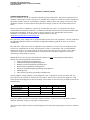
Towing adapters, jacking adapters, wheel alignment tools, compartment access door keys and any
other special tools required to maintain the bus shall be listed in the proposal and supplied to each
transit system receiving buses in this procurement. The number of each item to be provided is listed in the
following table:
Item
Towing Adapters
Jacking Adapters
Wheel Alignment Tools
Compartment Keys
Other Required Tools
1-20 Buses
21-40 Buses
41+ Buses
1
2
3
1
3
2
1
2
3
5
10
8
# as appropriate based upon # buses received
Test ports shall be provided for commonly checked functions on the bus such as air intake, exhaust,
hydraulic, pneumatic, charge-air and engine cooling systems.
The Contractor(s) shall provide a manual listing the times required for typical repair and service items on
the bus.
REQUEST FOR PROPOSALS FOR
PURCHASE AND DELIVERY OF HEAVY DUTY BUSES
RFP SRTA 2014-04
2
All systems or components subject to periodic maintenance or that are subject to periodic failures shall be
readily accessible for service and inspection. To the extent practicable, removal or physical movement of
components unrelated to the specific maintenance and/or repair tasks involved shall be unnecessary.
Components with identical functions shall be interchangeable to the extent practicable. These
components shall include, but not be limited to, passenger window hardware, interior trim, lamps, lamp
lenses, and seat assemblies. Components with non-identical functions shall not be, or appear to be,
interchangeable. A component shall not be used in an application for which it was neither designed nor
intended.
The bus shall achieve normal operation in ambient temperature ranges of 10° F to 115° F, at relative
humidity between 5 percent and 100 percent, and at altitudes up· to 3,000 feet above sea level.
Degradation of performance due to atmospheric conditions shall be minimized at temperatures below 10°
F, above 115° F, or at altitudes above 3,000 feet.
All the Massachusetts bus transit systems in this procurement operate in a high corrosion environment
due to the winter sand, salt and calcium chloride. The buses proposed should address these issues.
In the design and manufacture of the bus the Contractor(s) shall make every effort to reduce the
amount of potentially hazardous waste generated by all consortium members when maintaining
the bus in accordance with the procedures contained in the manufacturer's maintenance
manuals. The manufacturer shall use, whenever possible, all LED lighting, cleanable filters, and nonasbestos brake blocks and gaskets. In accordance with Section 6002 of the Resource Conservation and
Recovery Act the Contractor shall use, whenever possible and allowed by the specifications, recycled
materials in the manufacture of the bus.
The Contractor shall comply with all applicable Federal requirements defined in the Americans with
Disabilities Act, 49 CFR Part 38, and all State and Local regulations regarding mobility-impaired
persons.
BASIC BODY
The bus shall have a clean, smooth, modern design. The exterior and body features, including grilles and
louvers, shall be shaped to facilitate cleaning by automatic bus washers without snagging washer
brushes. Water and dirt shall not be retained in or on any body feature to freeze or bleed out onto the bus
after leaving the washer. The body and windows shall be sealed to prevent leaking of air, dust, or water
under normal operating conditions and during cleaning in automatic bus washers for the service life of the
bus. Exterior panels shall be sufficiently stiff to minimize vibration, drumming or flexing while the bus is in
service. When panels are lapped, the upper and forward panels shall act as a watershed. However if
entry of moisture into interior of vehicle is prevented by other means, then rear cap panels may be lapped
otherwise. The windows, hatches, and doors shall be able to be sealed. Accumulation on any window of the
bus of spray and splash generated by the bus' wheels on a wet road shall be minimized.
The bus body and roof structure shall withstand a static load equal to 150 percent of the curb weight
evenly distributed on the roof with no more than a 6 inch reduction in any interior dimension. Windows
shall remain in place and shall not open under such a load. These requirements must be met without
components such as roof mounted air conditioning installed.
The bus shall withstand a 25 mph impact by a 4,000 pound automobile at any point, excluding doorways,
along either side of the bus with no more than 3 inches of permanent structural deformation at seated
passenger hip height. This impact shall not result in sharp edges or protrusions in the bus interior.
Exterior panels below 35 inches from ground level shall withstand a static load of 2,000 pounds applied
perpendicular to the bus by a pad no larger than 5 inches square. This load shall not result in
REQUEST FOR PROPOSALS FOR
PURCHASE AND DELIVERY OF HEAVY DUTY BUSES
RFP SRTA 2014-04
3
deformation that prevents installation of new exterior panels to restore the original appearance of the
bus.
Body materials shall be selected and the body fabricated to reduce maintenance, extend durability, and
provide consistency of appearance throughout the service life of the bus. Detailing shall be kept simple; addon devices and trim, where necessary, shall be minimized and integrated into the basic design. The body
material surfaces shall be protected against graffitiand vandalism.
The bus flooring, sides, roof, understructure, axle suspension components shall resist corrosion or
deterioration from atmospheric conditions and road salts for a period of twelve (12) years or 500,000
miles whichever comes first. It shall maintain structural integrity and nearly maintain original appearance
throughout its service life, provided that it is maintained by all consortium members in accordance with the
procedures specified in the Contractor's service manual. With the exception of periodically inspecting
the visible coatings applied to prevent corrosion and reapplying these coatings in limited spots, the
Contractor shall not require the complete reapplication of corrosion compounds over the life of the bus.
All materials that are not inherently corrosion resistant shall be protected with corrosion-resistant
coatings. All joints and connections of dissimilar metals shall be corrosion-resistant and shall be
protected from galvanic corrosion. Representative samples of all materials and connections shall
withstand a two (2) week (336 hour) salt spray test in accordance with ASTM Procedure B-117 with no
structural detrimental effects to normally visible surfaces, and no weight loss of over 1 percent.
All structure, body, and panel-bending mode frequencies, including vertical, lateral, and torsional modes, shall
be sufficiently removed from all primary excitation frequencies to minimize audible, visible, or
sensible resonant vibrations during normal service.
The passenger and engine compartments shall be separated by a bulkhead(s) that shall, by incorporation of
fireproof materials in its construction, be a firewall. The engine compartment shall include areas where the
engine and exhaust systems are housed including the muffler, if mounted above the horizontal shelf. This
firewall shall preclude or retard propagation of an engine compartment fire into the passenger
compartment and shall be in accordance with the Recommended Fire Safety Practices defined in FTA
Docket 90, dated October 20, 1993. Only necessary openings shall be allowed in the firewall, and these shall
be fireproofed. Any passageways for the climate control system air shall be separated from the engine
compartment by fireproof material. Piping through the bulkhead shall have copper, brass, or fireproof
fittings sealed at the firewall with copper or steel piping on the forward side. Wiring may pass through
the bulkhead only if connectors or other means are provided to prevent or retard fire propagation through
the firewall. Engine access panels in the firewall shall be fabricated of fireproof material and secured
with fireproof fasteners. These panels, their fasteners, and the firewall shall be constructed and reinforced
to minimize warping of the panels during a fire that will compromise the integrity of the firewall.
The bus, loaded to GVWR and under static conditions, shall not exhibit deflection or deformation that
impairs the operation of the steering mechanism, doors, windows, passenger escape mechanisms and
service doors. Static conditions shall include the vehicle at rest with any one wheel or dual set of wheels on
a 6 inch curb or in a 6 inch deep hole.
Prior to acceptance of first bus, the structure of the bus shall have undergone appropriate structural
testing and/or analysis, including FTA required Altoona testing, to ensure adequacy of design for the
urban transit service. Any items that required repeated repairs or replacement must undergo the
corrective action with supporting test and analysis. A report clearly describing and explaining the failures and
corrective actions taken to ensure any and all such failures will not occur shall be submitted to SRTA.
Towing devices shall be provided on each end of the bus. Towing devices should accommodate flat
bedding or flat-towing. Each towing device shall withstand, without permanent deformation, tension
loads up to 1.2 times the curb weight of the bus within 20 degrees of the longitudinal axis of the bus. The
REQUEST FOR PROPOSALS FOR
PURCHASE AND DELIVERY OF HEAVY DUTY BUSES
RFP SRTA 2014-04
4
rear towing device(s) shall not provide a toehold for unauthorized riders. The front towing devices shall
allow attachment of adapters for a rigid tow bar and shall permit lifting and towing of the bus, at curb
weight, until the front wheels are clear off the ground. The rear towing devices shall permit lifting and
towing of the bus for a short distance, such as in cases of an emergency, to allow access to provisions
for front towing of bus. The method of attaching the tow bar or adapter shall require the specific
approval of SRTA. Each towing device shall accommodate a crane hook with a 1inch throat. The towing
device also needs to include a lighting plug for bus light operations from the towing vehicle and air ports to
allow the towing vehicle to maintain bus air pressure.
It shall be possible to safely jack up the bus, at curb weight, with a common 10 ton floor jack with or
without special adapter, when a tire or dual set is completely flat and the bus is on a level, hard surface,
without crawling under any portion of the bus. Jacking from a single point shall permit raising the bus
sufficiently high to remove and reinstall a wheel and tire assembly. Jacking pads located on the axle or
suspension near the wheels shall permit easy and safe jacking with the flat tire·or dual set on a 6 inch high
run-up block not wider than a single tire. Jacking and changing any one tire shall be completed by a mechanic
in less than 30 minutes from the time the bus is approached. The bus shall withstand such jacking at any
one or any combination of wheel locations without permanent deformation or damage. Jacking pads shall
be painted safety yellow or orange for ease of identification.
The bus axles or jacking plates shall accommodate the lifting pads of a two (2) post hoist system.
Jacking plates, if used as hoisting pads, shall be designed to prevent the bus from falling off the hoist. Other
pads or the bus structure shall support the bus on jack stands independent of the hoist.
Where the floor meets the walls of the bus, as well as other vertical surfaces, such as, platform risers, the
surface edges shall be blended with a circular section of radius not less than 1 inch. Similarly, a molding or
cove shall prevent debris accumulation between the floor and wheel housings. The vehicle floor in the area of
the entrance and exit doors shall have a lateral slope not exceeding 2 degrees to allow for drainage.
The floor deck may be integral with the basic structure or mounted on the structure securely to prevent
chafing or horizontal movement arid designed to last the life of the bus. Sheet metal screws shall not be used
to retain the floor and all floor fasteners shall be serviceable from one (1) side only. The use of
adhesives to secure the floor to the structure shall be allowed only in combination with the use of bolt or
screw fasteners and its effectiveness shall last throughout life of the coach. Tapping plates, if used for the floor
fasteners, shall be no less than the same thickness as a standard nut and all floor fasteners shall be secured
and protected from corrosion for the service life of the bus. The floor deck shall be reinforced as needed to
support passenger loads. At GVWR, the floor shall have an elastic deflection of no more than 0.60 inches
from the normal plane. The floor shall withstand the application of 2.5 times gross load weight without
permanent detrimental deformation. Floor, with coverings applied, shall withstand a static load of at least
150 pounds applied through the flat end of ½ inch-diameter rod, with 1/32 inch radius, without permanent
visible deformation.
The floor shall consist of the subfloor and the floor covering. The floor, as assembled, including the
sealer, attachments and covering shall be waterproof, non-hygroscopic, and impervious to mold growth.
The subfloor shall be SpaceAge Synthetics Thermo-Lite or equal composite flooring material that will
provide a minimum 150 pound weight savings per bus to the standard 3/4 inch marine plywood subfloor
product. The composite material shall be waterproof and will not rot, warp, mildew, allow mold growth,
split, soften, delaminate, will accept standard tooling and hardware, cannot be damaged by insects and
should last the life of a twelve (12) year bus.
Platform height shall not exceed 12 inches. Trim shall be provided along top edges of platforms unless
integral nosing is provided. Except where otherwise indicated, covering of platform surfaces and risers
shall be same material as specified for floor covering. Trim installed along edges of platforms shall be
constructed of stainless steel.
REQUEST FOR PROPOSALS FOR
PURCHASE AND DELIVERY OF HEAVY DUTY BUSES
RFP SRTA 2014-04
5
The operator's platform shall be of a height that, in a seated position,the operator can see an object
located at an elevation of 42 inches above the road surface, 24 inches from the leading edge of the
bumper. Notwithstanding this requirement, the platform height shall not position the operator such that
the operator's vertical upward view is less than 15 degrees.
If the driver's platform is higher than 12 inches, then the farebox is to be mounted on platform of
suitable height to provide accessibility for operator without compromising passenger's access.
If the vehicle is of a bi-level floor design, an intermediate platform shall be provided along the center
aisle of the bus to facilitate passenger traffic between the upper and lower floor levels. This
intermediate platform shall be cut into the rear platform and shall be approximately the aisle width, 18
inches deep and approximately the height of the upper level relative to the lower level. The
horizontal surface of this platform shall be covered with yellow Hypalon or equal ribbed rubber or skid
resistant material and shall be sloped slightly for drainage. A warning decal or sign shall be provided at the
immediate platform area to alert passengers to the change in floor level.
Sufficient clearance and air circulation shall be provided around the tires, wheels, and brakes to
preclude overheating when the bus is operating on the design operating profile.
Interference between the tires and any portion of the bus shall not be possible in maneuvers up to the limit
of tire adhesion with weights from curb weight to GVWR. Wheel housings shall be adequately
reinforced where seat pedestals are installed. Wheel housings shall have sufficient sound insulation to
minimize tire and road noise and meet all requirements.
Design and construction of front wheel housings shall allow for the installation of radio/electronic
equipment storage compartment on interior top surface or its use as a luggage rack.
The exterior finish of the front wheel housings shall be scratch-resistant and complement interior
finishes of the bus to minimize the visual impact of the wheel housing. If fiberglass wheel housings are
provided, then they shall be color-impregnated to match interior finishes. The lower portion extending
to approximately 12 inches above floor shall be equipped with additional more resistant coating or
stainless steel trim.
Wheel housings shall be constructed of corrosion-resistant, fire-resistant material. Wheel housings, as
installed and trimmed, shall withstand impacts of a 2 inch steel ball with at least 200 foot-pounds of
energy without penetration.
Exterior protrusions, greater than ½ inch and within 80 inches of the ground, shall have a radius no
less than the amount of the protrusion. The exterior rearview mirrors and required lights and reflectors
are exempt from the protrusion requirement. Grilles, doors, bumpers and other features on the sides
and rear of the bus shall be designed to minimize the ability of unauthorized riders to secure toeholds or
handholds.
Exterior panels below the lower daylight opening and within 35 inches above ground level shall be
divided into sections that are repairable or replaceable by a mechanic in less than thirty (30) minutes for
a section up to 5 feet long (excludes painting).
Lower exterior panels within 28 inches above ground level shall be equipped with removable resilient,
impact resistant panels for protection against minor impacts and scratches. The panels shall withstand
impacts of 200 foot-pounds of energy from a steel-faced spherical missile no less than 9 inches in
diameter without any visible damage to it or underlying panel and structure. The panels shall be no
greater than 8 feet in length and shall be easily replaced by a mechanic in less than ten (10) minutes.
The panels shall be color impregnated to complement color and paint scheme.
REQUEST FOR PROPOSALS FOR
PURCHASE AND DELIVERY OF HEAVY DUTY BUSES
RFP SRTA 2014-04
6
Rain gutters shall be provided to prevent water flowing from the roof onto the passenger doors,
operator's side window, and exterior mirrors. When the bus is decelerated, the gutters shall not drain
onto the windshield, or operator's side window, or into the door boarding area. Cross sections of the
gutters shall be adequate for proper operation. A rain gutter shall also be provided above passenger
side windows.
Provisions shall be made to recess mount standard size U.S. license plates per SAE J686 on the front
and rear of the bus. These provisions shall recess the license plates so that they can be cleaned by
automatic bus washing equipment without being caught by the brushes. License plates shall be mounted
at the lower center or lower street side of the bus and shall not allow a toehold or handhold for
unauthorized riders.
Features to minimize water spray from the bus in wet conditions shall be included in wheel housing
design. Any fender skirts shall be easily replaceable. They shall be flexible if they extend beyond the
allowable body width. Wheels and tires shall be removable with the fender skirts in place.
Splash aprons, composed of ¼ inch-minimum composition or rubberized fabric, shall be installed
behind and/or in front of wheels as needed to reduce road splash and protect underfloor
components. The splash aprons shall extend downward to within 4 inches of the road surface at static
conditions. Apron widths shall be no less than tire widths, except for the front apron that shall extend
across the width of the bus. Splash aprons shall be bolted to the bus understructure. Splash aprons and
their attachments shall be inherently weaker than the structure to which they are attached. The
flexible portions of the splash aprons shall not be included in the road clearance measurements. Other
splash aprons shall be installed where necessary to protect bus equipment.
Conventional or pantograph hinged doors shall be used for the engine compartment and for all
auxiliary equipment compartments. Access openings shall be sized for easy performance of tasks within
the compartment including tool operating space. Access doors shall be of rugged construction and shall
maintain mechanical integrity and function under normal operations throughout the service life of the
bus. They shall close flush with the body surface. All doors shall be hinged at the top or on the forward
edge and shall be prevented from coming loose or opening during transit service or in bus washing
operations. Doors with top hinges shall have safety props stored behind the door or on the doorframe.
All access doors shall be retained in the open position by props or counterbalancing with over-center
or gas-filled springs and shall be easily operable by one person. Spring and hinges shall be corrosion
resistant. Latch handles shall be flush with, or recessed behind, the body contour and shall be sized to
provide an adequate grip for opening. Access doors, when opened, shall not restrict access for servicing
other components or systems. Access doors larger in area than 100 square inches shall be equipped
with latches. The latches shall be standardized and shall be openable without the use of a key or tool.
Batteries shall be securely mounted on a stainless steel or equivalent tray that can accommodate the
size and weight of the batteries. The battery tray shall pull out easily and properly support the
batteries while they are being serviced. The tray shall allow each battery cell to be easily serviced
and filled. A locking device shall retain the battery tray in the stowed position.
The battery compartment or enclosure shall be vented and self-draining. It shall be accessible only from
outside the bus. All components within the battery compartment, and the compartment itself, shall be
protected from damage or corrosion from the electrolyte and gases emitted by the battery, and from
snow, slush, salt spray, mud, etc. generated from environmental conditions outside the vehicle. The inside
surface of the battery compartment's access door shall be electrically insulated, as required, to prevent
the battery terminals from shorting on the door if the door is damaged in an accident or if a battery
comes loose.
REQUEST FOR PROPOSALS FOR
PURCHASE AND DELIVERY OF HEAVY DUTY BUSES
RFP SRTA 2014-04
7
Lights shall be provided in the engine and all other compartments, where service may be required, to
generally illuminate the area for night emergency repairs or adjustments. Sealed lamp assemblies shall be
provided in the engine compartment and shall be controlled by a switch located near the rear start
controls in the engine compartment. Necessary lights, located in other service compartments, shall be
provided with switches on the light fixture or convenient to the light.
All exterior lights shall be designed to prevent entry and accumulation of moisture or dust, and each lamp
shall be replaceable in less than five (5) minutes by a mechanic. Commercially available LED type lamps shall
be used wherever possible. Lights mounted on the engine compartment doors shall be protected from the
impact shock of door opening and closing. Lamps, lenses and fixtures shall be interchangeable to the extent
practicable. Two (2) hazard lamps at the rear of the bus shall be visible from behind when the engine
service doors are opened. Light lenses shall be designed and located to prevent damage when running
the vehicle through an automatic bus washer. Lights located on the roof and sides (directionals) of the
bus shall have protective shields or be of the flush mount type to protect the lens against minor impacts.
Lamps at the front and rear passenger doorways shall comply with ADA requirements and shall activate
only when the doors open. These lamps shall illuminate the street surface to a level of no less than 1 foot
candle for a distance of 3 feet outward from the outboard edge of the door threshold. The·lights may be
positioned above or below the lower daylight opening of the windows and shall be shielded to protect
passengers' eyes from glare. Turn-signal lights shall be provided on both sides of the bus.
Visible and audible warning shall inform following vehicles or pedestrians of reverse operation. Visible
reverse operation warning shall conform to SAE Standard J593. Audible reverse operation warning shall
conform to SAE Recommended Practice J994 Type C or D.
Bumpers shall provide impact protection for the front and rear of the bus with the top of the bumper being
28 ½ inches above the ground. Bumper height shall be such that when one bus is parked behind another, a
portion of the bumper faces will contact each other.
No part of the bus, including the bumper, shall be damaged as a result of a 5 mph impact of the bus at curb
weight with a fixed, flat barrier perpendicular to the bus' longitudinal centerline. The bumper shall
return to its pre-impact shape within ten {10) minutes of the impact. The bumper shall protect the bus
from damage as a result of 6.5 mph impacts at any point by the Common Carriage with Contoured
Impact Surface defined in Figure 2 of FMVSS 301 loaded to 4,000 pounds parallel to the longitudinal
centerline of the bus and 5.5 mph impacts into the corners at a 30 degree angle to the longitudinal
centerline of the bus. The energy absorption system of the bumper shall be independent of every power
system of the bus and shall not require service or maintenance in normal operation during the service life of
the bus.
No part of the bus, including the bumper, shall be damaged as a result of a 2 mph impact with a fixed, flat
barrier perpendicular to the longitudinal centerline of the bus. The bumper shall return to its pre-impact
shape within ten (10) minutes of the impact. When using a yard tug with a smooth, flat plate bumper 2
feet wide contacting the horizontal centerline of the rear bumper, the bumper shall provide protection at
speeds up to 5 mph, over pavement discontinuities up to 1 inch high, and at accelerations up to 2
mph/sec. The rear bumper shall protect the bus, when impacted anywhere along its width by the
Common Carriage with Contoured Impact Surface defined in Figure 2 of FMVSS 301 loaded to 4,000
pounds, at 4 mph parallel to, or up to a 30 degree angle to, the longitudinal centerline of the bus. The
rear bumper shall be shaped to preclude unauthorized riders standing on the bumper. The bumper shall be
independent of all power systems of the bus and shall not require service or maintenance in normal
operation during the service life of the bus.
Bumper material shall be corrosion-resistant and withstand repeated impacts of the specified loads
without sustaining damage. Visible surfaces shall be black or color coordinated with the bus exterior.
These bumper qualities shall be sustained throughout the service life of the bus.
REQUEST FOR PROPOSALS FOR
PURCHASE AND DELIVERY OF HEAVY DUTY BUSES
RFP SRTA 2014-04
8
All materials shall be selected on the basis of maintenance, durability, appearance, safety, flammability, and
tactile qualities. Trim and attachment details shall be kept simple and unobtrusive. All materials shall be
strong enough to resist everyday abuse and vandalism; they shall be resistant to scratches and
markings. Interior trim shall be secured to avoid resonant vibrations under normal operational conditions.
Interior surfaces more than 10 inches below the lower edge of the side windows or windshield shall be
shaped so that objects placed on them fall to the floor when the coach is parked on a level surface. The entire
interior shall be cleanable with a hose, using a liquid soap attachment. Water and soap should not normally
be sprayed directly on the instrument and switch panels. An anti-graffiti/vandalism surface treatment
for interior surfaces shall be provided.
The entire front end of the bus shall be sealed to prevent debris accumulation behind the dash and to
prevent the operator's feet from kicking or fouling wiring and other equipment. The front end shall be free of
protrusions that are hazardous to passengers standing or walking in the front of the bus during rapid
decelerations. Paneling across the front of the bus and any trim around the operator's compartment shall be
formed metal or plastic material. Plastic dash panels shall be reinforced, as necessary, vandal
resistant, and replaceable. All colored, painted, and plated parts forward of the operator's barrier shall be
finished with a dull matte surface to reduce glare.
·
The rear bulkhead and rear interior surfaces shall be material suitable for exterior skin, painted and
finished to exterior quality, or paneled with melamine-type material, and trimmed with stainless steel,
aluminum, or plastic.
Interior side trim panels shall be Arborite Vogue P-925-S or equal material. The operator's barrier shall be
smoke color acrylic type material. Panels shall be easily replaceable and tamper-resistant. They shall be
reinforced, as necessary, to resist vandalism and other rigors of transit bus service. Individual trim panels
and parts shall be interchangeable to the extent practicable. Untrimmed areas shall be painted and
finished to the quality described in Section 5.4.3.10. All materials shall comply with the Recommended
Fire Safety Practices defined in FTA Docket 90, dated October 20, 1993.
A barrier or bulkhead between the operator and the street-side front passenger seat shall be provided.
The barrier shall minimize glare and reflections in the windshield directly in front of the barrier from
interior lighting during night operation.
An Operator's Barrier shall extend continually from floor to ceiling and from the bus wall to first
stanchion immediately behind the Operator to provide security to the Operator and limit passenger
conversation. Location and shape must permit full seat travel possibilities and accommodate the
shoulders of a 95th percentile male. The partition shall have a side return and stanchion to prevent
passengers from standing behind the Operator's seat; lower area between seat and panel must be
accessible to the Operator. The partition must be strong enough in conjunction with entire partition
assembly for mounting of such equipment as flare kits, fire extinguishers (1.2kg), microcomputer, public
address amplifier, etc. The partition shall start 1 inch above floor and dark or black panels are
preferred. The panel should be attached with rubber grommets.
An enclosed Operator storage area shall be provided with a positive latching door and lock; minimum
approximate size: 14 in. x 14 in. x 14 in.
Sturdy divider panels constructed of durable, unpainted, corrosion-resistant material complementing the
interior trim shall be provided to act as both a physical and visual barrier for seated passengers. Modesty
panels shall be located at doorways to protect passengers on adjacent seats, and along front edge of rear
upper level. Design and installation of modesty panels located in front of forward facing seats shall include
a handhold/grabhandle along its top edge. These dividers shall be mounted on the sidewall and shall
project toward the aisle no farther than passenger knee projection in longitudinal seats or the aisle side
of the transverse seats. Modesty panels shall extend no higher than the lower daylight opening of the side
REQUEST FOR PROPOSALS FOR
PURCHASE AND DELIVERY OF HEAVY DUTY BUSES
RFP SRTA 2014-04
9
windows and those forward of transverse seats shall extend downward to a level between 1% and 1 inches
above the floor. Panels forward of longitudinal seats shall extend to below the level of the seat cushion.
Dividers positioned at the doorways shall provide no less than a 2% inch clearance between the modesty
panel and the opened door to protect passengers from being pinched. Modesty panels installed at
doorways shall be equipped with grab rails. The modesty panel and its mounting shall withstand a static
force of 250 pounds applied to a 4 inch by 4 inch area in the center of the panel without permanent
visible deformation. A clear Plexiglas wind screen shall be provided on the modesty panel located in
front of the curb side seats directly behind the rear door.
The rear bulkhead paneling shall be contoured to fit the ceiling, side walls, and seat backs so that any litter,
such as a cigarette package or newspaper, will tend to fall to the floor or seating surface when the bus is
on a level surface. Any air vents in this area shall be louvered to reduce airflow noise and to reduce the
probability of trash or litter being thrown or drawn through the grille. If it is necessary to remove the
panel to service components located on the rear bulkhead, the panel shall be hinged or shall be able to
be removed and replaced by a mechanic in five (5) minutes. Grilles where access to or adjustment of
equipment is required shall be heavy duty and designed to minimize damage.
ENGINE
The propulsion system and drive· train shall provide power to enable the bus to meet the defined
acceleration, top speed, and gradability requirements, and operate all propulsion-driven accessories.
The propulsion system should be a Cummins ISL for Diesel, ISB for Hybrid or approved equal, and must meet
all 2014 EPA engine emissions. The buses shall be capable of achieving a top speed of 68 mph on a straight,
level road at GVWR with all accessories operating.
Gradability requirements shall be met on grades with a dry commercial asphalt or concrete pavement at
GVWR with all accessories operating. The propulsion system and drive train shall enable the bus to
achieve and maintain a speed of 40 mph on a 2% percent ascending grade and 7 mph on a 16 percent
ascending grade.
The bus acceleration shall meet the requirements as listed in the APTA "Standard Bus Procurement
Guidelines." The operating range of each bus when run on the transit coach duty cycle shall be at
least 350 miles.
The engine shall be tuned when delivered to provide optimized performance as specified above,
including fuel economy. All related components and configuration that affect fuel economy, such as, fan
control/operation, transmission, axle ratio, etc., shall be selected accordingly. The bus shall achieve an
average fuel economy of 4.00 miles per gallon when run on the Transit Coach Duty Cycle loaded to SLW.
Reference SAE J1376, Fuel Economy Measurement Test (Engineering Type) for Trucks and Buses.
The engine shall be designed to operate for not less than 300,000 miles without major failure or
significant deterioration. Components of the fuel injector and/or control system shall be designed to
operate for not less than 150,000 miles without replacement or major service.
The engine shall be designed to operate on Nos. 1 or 2 ultra low sulfur diesel fuel and up to 20 percent
Biodiesel. The engine shall be equipped with an electronically controlled management system.
The engine control system shall have onboard diagnostic capabilities able to monitor vital engine
functions, store and time stamp out of parameter conditions in memory, and communicate faults and
vital conditions to service personnel. Diagnostic reader device connector ports, suitably protected
against dirt and moisture, shall be provided in operator's area and near or inside engine compartment.
The engine starter shall be protected by an interlock that prevents its engagement when the engine is
running. The engine shall be equipped with an operator-controlled fast idle device. The fast idle
REQUEST FOR PROPOSALS FOR
PURCHASE AND DELIVERY OF HEAVY DUTY BUSES
RFP SRTA 2014-04
10
control shall be a two-way toggle mounted on the dash or side console and shall activate only with the
transmission in neutral and the parking brake applied.
The engine control system shall protect the engine against progressive damage. The system shall
monitor conditions critical for safe operation and automatically derate power and/or speed and initiate
engine shutdown as needed. The on-board diagnostic system shall trigger a visual and audible alarm to
the operator when the engine control unit detects a malfunction and the engine protection system is
activated.
Automatic shutdown shall only occur when the following parameters established for the functions below
are exceeded: Coolant Level, Coolant Temperature, Oil Pressure and Oil Temperature.
The optional hybrid drive propulsion system shall be provided for each bus size. The hybrid propulsion
system shall be an Allison E40, BAE HybriDrive, ISE Thudervolt/Siemans or equal design. It must have
been installed and operating on a minimum 100 transit buses for a minimum of one (1) year at the time
of proposal submission. The traction electrical storage shall be nickel metal hydride or Lithium Jon batteries
or Ultracapacitors. Lead acid batteries for traction storage will not be accepted.
The cooling systems shall be of sufficient size to maintain all engine and transmission fluids and
engine intake air at safe, continuous operating temperatures during the most severe operations
possible and in accordance with engine and transmission manufacturers' cooling system requirements.
The cooling system fan/fans control should sense the temperatures of the operating fluids and the
intake air and if either is above safe operating conditions the cooling fan should be engaged. The fan
control system shall be designed with a fail-safe mode of "fan on". The cooling system in new
condition shall have an ambient capacity of at least 110 degree F with water as coolant and sea
level operation.
The engine shall be cooled by a water-based, pressure type, cooling system that does not permit
boiling or coolant loss during the operations described above. Engine thermostats shall be easily
accessible for replacement. Shutoff valves shall allow filter replacement without coolant loss. Valves
shall permit complete shutoff of lines for the heating and defroster units, and water booster pumps.
The water boost pump shall be a magnetically coupled, brushless and seal less design. All low points in
the water-based cooling system shall be equipped with drain cocks. Air vent valves shall be fitted at high
points in the cooling system unless it can be demonstrated that the system is self-purging.
A sight glass to determine satisfactory engine coolant level shall be provided and shall be accessible by
opening the engine compartment door. A spring-loaded, push button type valve to safely release
pressure or vacuum in the cooling system shall be provided with both it and the water filler no more
than 60 inches above the ground and both shall be accessible through the same access door.
The engine shall meet all applicable emission standards. Exhaust gases and waste heat shall be
discharged from the roadside rear comer of the roof. The exhaust pipe shall be of sufficient height to
prevent exhaust gases and waste heat from discoloring or causing heat deformation to the bus roof. The
entire exhaust system shall be adequately shielded to prevent heat damage to any bus
component. The exhaust outlet shall be designed to minimize rain, snow or water generated from·
high-pressure washing systems from entering into the exhaust pipe and causing damage to the
catalyst.
The power plant shall be mounted in a compartment in the rear of the bus. All power plant mounting
shall be mechanically isolated to minimize transfer of vibration to the body structure. Mounts shall
control movement of the power plant so as not to affect performance of belt driven accessories or cause
strain in piping and wiring connections to the power plant.
The power plant shall be arranged so that accessibility for all routine maintenance is assured. No
REQUEST FOR PROPOSALS FOR
PURCHASE AND DELIVERY OF HEAVY DUTY BUSES
RFP SRTA 2014-04
11
special tools, other than dollies and hoists, shall be required to remove the power plant. Two (2}
mechanics shall be able to remove and replace the engine and transmission assembly in less than twelve
(12} total combined man-hours. The muffler, exhaust system, air cleaner, air compressor, starter,
alternator, radiator, all accessories, and any other component requiring service or replacement shall be
easily removable and independent of the engine and transmission removal. An engine oil pressure
gauge and coolant temperature gauge shall be provided in the engine compartment. These gauges shall be
easily read during service and mounted in an area where they shall not be damaged during minor or
major repairs.
Engine oil and the radiator filler caps shall be hinged to the filler neck and closed with spring pressure or
positive locks. All fluid fill locations shall be properly labeled to help ensure correct fluid is added and
all fillers shall be easily accessible with standard funnels, pour spouts, and automatic dispensing
equipment. All lubricant sumps shall be fitted with magnetic-type, external, hex head, self sealing drain
plugs.
The engine and transmission shall be equipped with sufficient heavy-duty fuel and oil filters for efficient
operation and to protect the engine and transmission between scheduled filter changes.
To the extent practicable, the filters shall be of the spin-on, disposable type or integral with the engine
and transmission. All filters shall be easily accessible and the filter bases shall be plumbed to assure
correct reinstallation. The engine shall be equipped with a fuel-priming pump or a check valve fitted in
the fuel suction line to aid restarting after fuel filter changes.
A Spinner II Model 976 or equal centrifugal, non-disposable bypass engine oil filter shall be provided.
An air cleaner with a dry filter element and a graduated air filter restriction indicator shall be provided.
The filter shall be removable by a mechanic in ten (10} minutes or less. The location of the air intake
system shall be designed to minimize the entry of dust and debris and maximize the life of the air filter.
The engine air duct shall be designed to minimize the entry of water into the air intake system.
Drainage provisions shall be included to allow any water/moisture to drain prior to entry into air filter.
Engine-driven accessories shall be mounted for quick removal and repair. Accessory drive systems
shall operate without unscheduled adjustment for not less than 50,000 miles on the design operating
profile. These accessories shall be driven at speeds sufficient to assure adequate system
performance during extended periods of idle operation and low route speed portion of the design
operating profile. Belt guards shall be provided as required for safety and shall be sturdy in design and
installation and readily removable.
Any accessory may be driven hydraulically or electrically. The hydraulic system shall demonstrate a
mean time between repairs in excess of 50,000 miles. Hydraulic system service tasks shall be
minimized and scheduled no more frequently than those of other major coach systems. All elements of the
hydraulic system shall be easily accessible for service or unit replacement. Critical points in the
hydraulic system shall be fitted with service ports so that portable diagnostic equipment may be
connected or sensors for an off-board diagnostic system permanently attached to monitor system
operation. A tamper-proof priority system shall prevent the loss of power steering during operation of
the bus if other devices are also powered by the hydraulic system. Sensors in the hydraulic system,
excluding those in the power steering system, shall indicate on the operator's on-board diagnostic
panel conditions of low hydraulic fluid level.
All fluid lines and air piping shall be rigidly supported to prevent chafing damage, fatigue failures, and
tension strain. Lines passing through a panel, frame, or bulkhead shall be protected by grommets (or
similar device) that fit snugly to both the line and the perimeter of the hole that the line passes through to
prevent chafing and/or wear.
REQUEST FOR PROPOSALS FOR
PURCHASE AND DELIVERY OF HEAVY DUTY BUSES
RFP SRTA 2014-04
12
Flexible fuel and oil lines shall be kept at a minimum and shall be as short as practicable. Flexible lines shall
be routed or shielded so that failure of a line shall not allow fuel or oil to spray or drain onto any
component operable above the auto-ignition temperature of the fluid. Flexible lines shall be Teflon
hoses with braided stainless steel jackets except in applications where premium hoses are required and
shall have standard SAE or JIC brass or steel, swivel, end fittings. Flexible hoses over 1 inch in diameter
need not be Teflon with braided stainless steel jacket but shall be in conformance with SAE Standard
J100R5. Flexible hoses and fluid lines shall not touch one another, or any part of the bus.
Lines shall have a maximum length of 6 feet unless demonstrated inappropriate for a given application.
Hoses/lines shall be secured with heavy-duty stainless steel, full silicone rubber clamps.
Compression fittings shall be standardized as much as practicable to prevent the intermixing of
components. Compression fitting components from more than one manufacturer shall not be mixed
even if the components are known to be interchangeable.
The vehicle engine compartment shall be equipped with an AMEREX ABC dry chemical pre
engineered fire suppression system model V25 or equal. The system shall be approved and listed for use
at -65° F to 150° F by Factory Mutual Research Corporation. The automatic actuation system shall
provide twenty-four (24) hour fire detection. The system shall also be activated manually by
depressing an electric switch (button with pull pin, labeled 'fire') mounted in the driver's dash area. An
inspection door will be provided by the OEM on the bus body allowing for visual site inspection of the
agent cylinder gauge.
Fuel lines shall be rated and sized to prevent freezing and plugging due to condensation and/or fuel
gelling in extreme winter. The fuel lines forward of the engine bulkhead shall be in conformance to
SAE Standard J1149 Type 1 for copper tubing, corrosion-resistant stainless steel tubing or SAE
Standard J844 for nylon tubing color coded orange. The fuel lines forward of the engine bulkhead shall be in
conformance to the SAE Standards.
The fuel tank(s) shall be equipped with an external, hex head, brass drain plug. It shall be at least a 3/8
inch size and shall be located at the lowest point of the tank(s). The fuel tank(s) shall have an
inspection plate or easily removable filler neck to permit cleaning and inspection of the tank(s) without
removal from the bus. The tank(s) shall be baffled internally to prevent fuel-sloshing noise regardless of
fill level. The baffles or fuel pickup location shall assure continuous full power operation on a 6
percent upgrade for fifteen (15) minutes starting with no more than 25 gallons of fuel over the unusable
amount in the tank(s). The bus shall operate at idle on a 6 percent downgrade for thirty (30) minutes
starting with no more than 10 gallons of fuel over the unusable amount in the tank(s).
The fuel tank(s) shall be made of corrosion resistant stainless steel and shall be securely mounted to the
bus by corrosive resistant stainless steel straps or equivalent that prevents movement prevent during bus
maneuvers, but shall be capable of being removed and reinstalled by a mechanic for cleaning or
replacement in ninety (90) minutes or less.
The capacity, date of manufacture, manufacturer name, location of manufacture, and certification of
compliance to FMCSR shall be permanently marked on the fuel tank(s). The markings shall be readily
visible and shallnot be covered with an undercoating material.
The fuel filler shall be an Emco Wheaton or equal system and accommodate a nozzle that forms a
locked and sealed connection during the refueling process to eliminate spills. Fuel shall not be allowed to
flow into the tank unless the nozzle has been properly coupled, locked and sealed to the filler. With the
nozzle open, fuel shall enter the tank at a fill rate of not less than 40 gallons per minute of foam - free
fuel without causing the nozzle to shut off before the tank is full. The nozzle shall automatically shut off
when the tank is essentially full. Once disconnected, fuel shall not be allowed to flow through the nozzle at
any time. Any pressure over3 psi shall be relieved from the fuel tank automatically. An audible signal shall
REQUEST FOR PROPOSALS FOR
PURCHASE AND DELIVERY OF HEAVY DUTY BUSES
RFP SRTA 2014-04
13
indicate when the tank is essentially full. The fuel filler shall be located 7 to 25 feet behind the centerline of
the front door on the curbside of the bus. The filler cap shall be retained to prevent loss and shall be
recessed into the body so that spilled fuel will not run onto the outside surface of the bus.
Oil and hydraulic lines shall be compatible with the fluid they carry. The lines shall be designed and
intended for use in the environment which they are installed, i.e., high temperatures in engine
compartment, road salts, oils, etc. Lines shall be capable of withstanding maximum system pressures. Lines
within the engine compartment shall be composed of steel tubing where practicable except in locations
where flexible lines are specifically required. Hydraulic lines of the same size and with the same fittings
as those on other piping systems of the bus, but not interchangeable, shall be tagged or marked for use on
the hydraulic system only.
TRANSMISSION
The transmission shall be cooled by a separate heat exchanger sized to maintain operating fluid within the
transmission manufacturer's recommended parameters of flow, pressure and temperature. The
transmission cooling system shall be matched to retarder and engine cooling systems to ensure that all
operating fluids remain within recommended temperature limits established by each component
manufacturer.
The transmission shall be an Allison B400R, B500R or equal sized appropriately for the buses in this
procurement. All transmissions shall be factory filled with Castro Transynd synthetic transmission fluid
or equal fluid. The transmission shall be multiple speed, automatic shift with torque converter, retarder
and electronic controls. Gross input power, gross input torque arid rated input speed shall be
compatible with the engine. A mechanic, with optional assistance, shall be able to remove and replace
the transmission assembly for service in less than sixteen (16) total combined man-hours. The
transmission shall be designed to operate for not less than 300,000 miles on the design operating
profile without replacement or major service.
The electronic controls shall be capable of transmitting and receiving electronic inputs and data from
other Drivetrain components and broadcasting that data to other vehicle systems. Electronic controls
shall be compatible with either 12 or 24 volt power distribution, provide consistent shift quality, and
compensate for changing conditions such as variations in vehicle weight and engine power. A brake
pedal application of 15 to 20 psi shall be required by the operator to engage forward or reverse range
from the neutral position to prevent sudden acceleration of the bus from a parked position.
The electronically controlled transmission shall have on-board diagnostic capabilities, be able to monitor
functions, store and time stamp out-of-parameter conditions in memory, and communicate faults and
vital conditions to service personnel. The transmission shall contain built-in protection software to
guard against severe damage. A diagnostic reader device connector port, suitably protected against dirt
and moisture, shall be provided in the operator's area. The on-board diagnostic system shall trigger a
visual alarm to the operator when the electronic· control unit detects a malfunction.
An electronic transmission fluid level monitoring and protection system shall be provided. This system
shall allow a mechanic to accurately determine transmission fluid levels during checking or oil change
and shall be in addition to the manual dipstick. This system shall also provide protection against any
damage resulting from improper fluid level conditions.
The transmission shall have an auto neutral feature that shall cause it to automatically and immediately
shift to "Neutral" whenever the transmission is left in gear and the parking brake is applied. This system
shall also automatically shift the transmission to "Neutral," after a five (5) minute delay, whenever the
exit door brake interlock is applied.
The transmission shall be equipped with an integral hydraulic retarder designed to extend brake lining
service life. The application of the retarder shall cause a smooth blending of both retarder and service
REQUEST FOR PROPOSALS FOR
PURCHASE AND DELIVERY OF HEAVY DUTY BUSES
RFP SRTA 2014-04
14
brake functions without exceeding jerk requirements. Brake lights shall illuminate when the retarder is
activated.
The retarder shall become partially engaged (approximately ¼ to 1 / 3 of its total application, with a
resulting deceleration of no greater than 0.03g) when the throttle is completely released (e.g., zero
throttle). Maximum retarder shall be achieved when brake pedal is depressed prior to engagement of
service brakes with a maximum resulting deceleration of approximately 0.13g. The resulting
decelerations specified include the effects of engine braking, wind resistance and rolling resistance.
The thermostatically controlled cooling fan shall be activated when the retarder is engaged and the
coolant temperature exceeds the maximum limit established by the engine and transmission
manufacturers.
The retarder on/off switch shall be located in the engine compartment at a location approved during
pre-production.
Jerk, the rate of change of acceleration measured at the centerline, floor level of the bus shall be
minimized throughout the shifting of each transmission range and retarder application and shall be no
greater than 0.3g/sec. for duration of a quarter-second or more.
AXLES
The front axle shall be a Meritor or equal solid beam, non-driving with a load rating sufficient for the bus
loaded to GVWR and shall be equipped· with oil lubricated front wheel bearings and seals. All friction
points on the front axle shall be equipped with replaceable bushings or inserts and lubrication fittings
easily accessible from a pit or hoist.
Fatigue life of all steering components shall exceed 1,000,000 miles. No element of the steering
system shall sustain a Class I failure when one of the tires hits a curb or strikes a severe road hazard.
Inadvertent alternations of steering as a result of striking road hazards are steering failures.
The bus shall be driven by a single heavy-duty Meritor or equal axle at the rear with a load rating
sufficient for the bus loaded to GVWR. Transfer of gear noise to the bus interior shall be minimized.
The drive axle shall be designed to operate for not less than 300,000 miles on the design operating
profile without replacement or major repairs. The lubricant drain plug shall be magnetic type, external
hex head. If a planetary gear design is employed, the oil level in the planetary gears shall be easily
checked through the plug or sight gauge. The drive shaft shall be guarded to prevent it striking the
floor of the coach or the ground in the event of a tube or universal joint failure.
SUSPENSION SYSTEM
Both the front and rear suspensions shall be pneumatic type. The basic suspension system shall last the
service life of the bus without major overhaul or replacement. Normal replacement items, such as one
(1) suspension bushing, shock absorbers, or air spring shall be replaceable by a mechanic in thirty (30)
minutes or less. Adjustment points shall be minimized and shall not be subject to a loss of
adjustment in service. Necessary adjustments shall be easily accomplished without removing or
disconnecting the components.
The suspension system shall permit a minimum wheel travel of 3 inches jounce-upward travel of a
wheel when the bus hits a bump (higher than street surface), and 3 inches rebound-downward travel
when the bus comes off a bump and the wheels fall relative to the body. Elastomeric bumpers shall be
provided at the limit of jounce travel. Rebound travel may be limited by elastomeric bumpers or
hydraulically within the shock absorbers. Suspensions shall incorporate appropriate devices for
automatic height control so that regardless of load the bus height relative to the centerline of the
wheels does not change more than ± % inch at any point.
REQUEST FOR PROPOSALS FOR
PURCHASE AND DELIVERY OF HEAVY DUTY BUSES
RFP SRTA 2014-04
15
Vertical damping of the suspension system shall be accomplished by hydraulic shock absorbers
mounted to the suspension arms or axles and attached to an appropriate location on the chassis.
Damping shall be sufficient to control coach motion to three (3) cycles or less after hitting road
perturbations. Shock absorbers shall maintain their effectiveness for at least 50,000 miles of the
service life of the bus. Each unit shall be replaceable by a mechanic in less than fifteen (15) minutes.
The shock absorber bushing shall be made of elastomeric material that will last the life of the shock
absorber.
All elements of steering, suspension, and drive systems requiring scheduled lubrication shall be
provided with grease fittings conforming to SAE Standard J534. These fittings shall be located for ease
of inspection, and shall be accessible with a standard grease gun without flexible hose end from a pit or with
the bus on a hoist. Each element requiring lubrication shall have its own grease fitting with a relief path.
Lubricant specified shall be standard for all elements on the bus serviced by standard fittings.
A kneeling system shall lower the entrance(s) of the bus a minimum of 2 1/2 inches during loading or
unloading operations regardless of load up to GVWR, measured at the longitudinal centerline of the
entrance door(s), by the driver using a three position, spring loaded to center switch. Downward
direction will lower the bus. Release of switch at anytime will completely stop lowering motion and hold
height of the bus at that position. Upward direction of the switch will allow the system to go to floor
height without the driver having to hold the switch up.
Brake and Throttle interlock shall prevent movement when the bus is kneeled. The kneeling control
shall be disabled when the bus in motion. The bus shall kneel at a maximum rate of ¼ inches per second
at essentially a constant rate. After kneeling, the bus shall rise within 2 seconds to a height permitting
the bus to resume service and shall rise to the correct operating height within 7 seconds regardless of
load up to GVWR. During the lowering and raising operation, the maximum acceleration shall not exceed
0.2g and the jerk shall not exceed 0.3g/sec.
An indicator visible to the driver shall be illuminated until the bus is raised to a height adequate for safe
street travel. An audible warning alarm will sound simultaneously with the operation of the kneeler to
alert passengers and bystanders. A warning light mounted near the curbside of the front door,
minimum 3 inches diameter, amber lens shall be provided that will blink when the kneel feature is
activated. Kneeling shall not be operational while the wheelchair ramp or lift is deployed or in
operation.
WHEELS AND TIRES
Rims shall be hub-piloted Alcoa aluminum wheels with Dura-Brite. All wheels shall be interchangeable and
shall be removable without a puller. Wheels shall be compatible with tires in size and load-carrying
capacity. Front wheels and tires shall be balanced as an assembly per SAE J1986.
Tires shall be provided by the Contractor installed on each bus suitable for the conditions of transit
service and sustained operation at the maximum speed capability of the bus. Load on any tire at
GVWR shall not exceed the tire supplier's rating. A spare tire on a rim shall be provided with every
bus.
The buses in this procurement shall be equipped with a standard hub odometer mounted at the
curbside of the rear axle. The hub odometer shall have a capacity reading no less than 999,999 miles in
full mile increments (no tenths of a mile).
STEERING
The steering wheel shall be removable with a standard or universal puller. The steering column shall
have full tilt and telescoping capability allowing the operator to easily adjust the location of the steering
wheel.
REQUEST FOR PROPOSALS FOR
PURCHASE AND DELIVERY OF HEAVY DUTY BUSES
RFP SRTA 2014-04
16
Hydraulically assisted power steering shall be provided. The steering gear shall be an integral type with
flexible lines eliminated or the number and length minimized. With the bus on dry, level, commercial
asphalt pavement, and tires inflated to recommended pressure and the front wheels positioned
straight ahead, the torque required to turn the steering wheel 10 degrees shall be no less than 5 foot pounds
and no more than 10 foot pounds. Steering torque may increase to 70 foot pounds when the wheels are
approaching the steering stops, as the relief valve activates. Steering effort shall be measured with the bus
at GVWR, stopped with the brakes released and the engine at normal idling speed on clean, dry, level,
commercial asphalt pavement and the tires inflated to recommended pressure. Power steering failure
shall not result in loss of steering control. With the bus in operation the steering effort shall not exceed
55 pounds at the steering wheel rim and perceived free play in the steering system shall not materially
increase as a result of power assist failure. Gearing shall require no more than seven (7) turns of the
steering wheel lock-to-lock.
Caster angle shall be selected to provide a tendency for the return of the front wheels to the straight
position with minimal assistance from the driver.
The steering wheel diameter shall be no less than 18 inches and no more than 20 inches; the rim
diameter shall be 7/8 inches to 1 ¼ inches and shaped for firm grip with comfort for long periods of
time. The steering wheel shall be black in color and a rounded three spoke design.
Steering wheel spokes and wheel thickness should be such as to insure that visibility is within the
range of a 95th percentile range as described in SAE 1050a, section 4.2.2 and 4.2.3. Placement of
steering column must be as far forward as possible, but either in-line or behind the instrument cluster.
The steering wheel shall have a rearward tilt adjustment range of no less than 40 degrees as
measured from the horizontal and upright position.
BRAKES
Service brakes shall be controlled and actuated by a compressed air system. Force to activate the
brake pedal control shall be an essentially linear function of the bus deceleration rate and shall not
exceed 50 pounds at a point 7 inches above the heel point of the pedal to achieve maximum braking. The
heel point is the location of the driver's heel when foot is rested flat on the pedal and the heel is touching
the floor or heel pad of the pedal. A microprocessor controlled ABS shall be provided. The
microprocessor for the ABS system shall be protected yet in an accessible location to allow for ease of
service. The total braking effort shall be distributed between all wheels in such a ratio as to ensure
equal friction material wear rate at all wheel locations
Microprocessor controlled ATC shall be provided. Actuation of ABS and/or ATC shall override the
operation of the brake retarder.
The entire service brake system, including friction material, shall have a minimum overhaul or
replacement life of 30,000 miles with a brake retarder on the design operating profile. Brakes shall be
self-adjusting throughout this period. Visible stroke indicators shall be provided to allow service
personnel to easily identify when the brakes are not in correct adjustment. The brake linings shall be
made of non-asbestos material. In order to aid maintenance personnel in determining extent of wear, a
provision such as a scribe line or chamfer indicating the thickness at which replacement becomes
necessary, shall be provided on each brake lining.
Replaceable wheel bearing seals shall run on replaceable wear surfaces or be of an integral wear
surface sealed design. Oil lubricated wheel bearings and hub seals shall not leak or weep lubricant for
100,000 miles when running on the design operating profile.
The bus shall be equipped with brake drums or disk brakes. Brake drums shall allow machining to ¼
inch oversize.
REQUEST FOR PROPOSALS FOR
PURCHASE AND DELIVERY OF HEAVY DUTY BUSES
RFP SRTA 2014-04
17
The brake system material and design shall be selected to absorb and dissipate heat quickly so the heat
generated during braking operation does not glaze brake linings. The heat generated shall not increase
the temperature of tire beads and wheel contact area to more than that allowed by the tire
manufacturer.
The parking brake shall be a spring-operated system, actuated by a valve that exhausts compressed air to
apply the brakes. The parking brake may be manually enabled when the air pressure is at the operating
level per FMVSS 121. An emergency brake release shall be provided to release the brakes in the event of
automatic emergency brake application. The parking brake valve button will pop out when air pressure
drops below requirements of FMVSS 121. The driver shall be able to manually depress and hold down
the emergency brake release valve to release the brakes and maneuver the bus to safety. .Once the
operator releases the emergency brake release valve, the brakes shall engage to hold the bus in place.
COOLING
The radiator, and charge air cooler if integrated, shall be of durable corrosion-resistant construction
with bolted-on removable tanks. The radiator shall be designed so a mechanic can gain access to a
substantial portion of the side facing the engine for the purpose of cleaning the radiator in five (5)
minutes or less.
Radiators with a fin density greater than 12 fins per inch, and louvered/slit designs, are more
susceptible to clogging and deteriorating cooling performance over time and shall not be used.
No heat producing components or climate control system components shall be mounted between the
engine cooling air intake aperture and the radiator. The radiator and charge air cooler shall be
designed to withstand thermal fatigue and vibration associated with the installed configuration.
The engine cooling system shall be equipped with a properly sized water filter with a spin-on element
and an automatic system for releasing supplemental coolant additives as needed to replenish and
maintain protection properties.
The cooling fan shall be temperature controlled, allowing the engine to reach operating temperature
quickly. The temperature-controlled fan shall not be driven when the coolant temperature falls below
the minimum level recommended by the engine manufacturer.
The charge air cooling system also referred to as after-coolers or inter-coolers, shall provide maximum air
intake temperature reduction with minimal pressure loss. The charge air radiator shall be sized and
positioned to meet engine manufacturer's requirements. The charge air radiator shall not be stacked
ahead or behind the engine radiator and shall be positioned as close to the engine as possible unless
integrated with the radiator. Air ducting and fittings shall be protected against heat sources, and shall be
configured to minimize restrictions and maintain sealing integrity.
Radiator piping shall be stainless steel or brass tubing and, if practicable, hoses shall be eliminated.
Necessary hoses shall be premium, silicone rubber type that is impervious to all bus fluids. All hoses shall
be as short as practicable. All hoses shall be secured with premium, stainless steel clamps that provide a
complete 360 degree seal. The clamps shall maintain a constant tension at all times, expanding and
contracting with the hose in response to temperature changes and aging of the hose material.
PNEUMATIC SYSTEMS
The bus air system shall operate the air-powered accessories and the braking system with reserve
capacity. New buses shall not leak down more than 5 psi as indicted on the instrument panel mounted air
gauges, within fifteen (15} minutes from the point of governor cut-off.
REQUEST FOR PROPOSALS FOR
PURCHASE AND DELIVERY OF HEAVY DUTY BUSES
RFP SRTA 2014-04
18
Provision shall be made to apply shop air to the bus air systems using a standard tire inflation type valve.
Lincoln Air Quick Disconnect #11659 or equal quick disconnect fittings shall be easily accessible
and located in the engine compartment and near the front bumper area for towing. Retained caps
shall be installed to protect fitting against dirt and moisture when not in use. Air for the compressor shall
be filtered through the main engine air cleaner system. The air system shall be protected by a pressure
relief valve set at 150 psi and shall be equipped with check valve and pressure protection valves to assure
partial operation in case of line failures.
The engine-driven air compressor shall be sized to charge the air system from 40 psi to the governor cutoff
pressure in less than three (3} minutes while not exceeding the fast idle speed setting .of the engine.
Air lines, except necessary flexible lines, shall conform to the installation and material requirements of SAE
Standard. J1149 for copper tubing with standard, brass, flared or ball sleeve fittings, or SAE Standard
J844 for nylon tubing if not subject to temperatures over 200° F. Nylon tubing shall be installed in
accordance with the following color-coding standards:
Green
Indicates primary brakes and supply
Red
Indicates secondary brakes
Brown
Indicates parking brake
Yellow
Indicates compressor governor signal
Black
Indicates accessories
Line supports shall prevent movement, flexing, tension strain, and vibration. Copper lines shall be
supported to prevent the lines from touching one another or any component of the bus. To the extent
practicable and before installation, the lines shall be pre-bent on a fixture that prevents tube flattening or
excessive local strain. Copper lines shall be bent only once at any point, including pre-bending and
installation. Rigid lines shall be supported at no more than 5 foot intervals. Nylon lines may be
grouped and shall be supported at 2 foot intervals or less.
The compressor discharge line between power plant and body-mounted equipment shall be flexible
convoluted copper or stainless steel line, or may be flexible Teflon hose with a braided stainless steel jacket.
Other lines necessary to maintain system reliability shall be flexible Teflon hose with a braided stainless
steel jacket. End fittings shall be standard SAE or JIC brass or steel, flanged, swivel type fittings. Flexible
hoses shall be as short as practicable and individually supported. They shall not touch one another or
any part of the bus except for the supporting grommets. Flexible lines shall be supported at 2 foot
intervals or less.
Air lines shall be clean before installation and shall be installed to minimize air leaks. All air lines shall be
sloped toward a reservoir and routed to prevent water traps. Grommets or insulated clamps shall protect
the air lines at all points where they pass through understructure components.
All air reservoirs shall meet the requirements of FMVSS Standard 121 and SAE Standard J10 and shall be
equipped with clean-out plugs and guarded or flush type drain valves. Major structural members shall
protect these valves and any automatic moisture ejector valves from road hazards. Reservoirs shall be
sloped toward the drain valve. All air reservoirs shall have brass drain valves which discharge below floor
level with lines routed to eliminate the possibility of water traps and/or freezing in the drain line.
An air dryer shall prevent accumulation of moisture and oil in the air system. The air dryer system shall
include a replaceable desiccant bed, electrically heated drain, and activation device. A mechanic shall be
able to replace the desiccant in less than fifteen (15) minutes. An oil separator shall be provided between
the compressor and dryer.
Charge air piping and fittings shall be designed to minimize air restrictions and leaks. Piping shall be as
REQUEST FOR PROPOSALS FOR
PURCHASE AND DELIVERY OF HEAVY DUTY BUSES
RFP SRTA 2014-04
19
short as possible and the number of bends shall be minimized. Bend radii shall be maximized to meet the
pressure drop and temperature rise requirements of the engine manufacturers. The cross section of all
charge air piping shall not be less than the cross section of the intake manifold inlet. Any change in pipe
diameter shall be gradual to ensure a smooth passage of air and to minimize restrictions. Piping shall be
routed away from exhaust manifolds and other heat sources, and shielded as required to meet the
temperature rise requirements of the engine manufacturer.
Charge air piping shall be constructed of stainless steel, aluminized steel or anodized aluminum,
except between the air filter and turbocharger inlet where piping may be constructed of fiberglass.
Connections between all charge air piping sections shall be sealed with a short section of reinforced hose
and secured with stainless steel, constant tension clamps that provide a complete 360 degree seal.
HEATING, VENTILATION AND AIR CONDITIONING EQUIPMENT
The HVAC unit shall be a Thermo King T-Series or equal incorporating a bus rear-mount with a screw type
compressor design.
With the bus running at the design operating profile with corresponding door opening cycle, and carrying
a number of passengers equal to 150 percent of the seated load, the HVAC system shall maintain an
average passenger compartment temperature within a range between 65°F and 80°F, while controlling
the relative humidity to a value of 50 percent or Jess. The system shall maintain these conditions while
subjected to any outside ambient temperatures within a range of 10°F to 95°F and at any ambient relative
humidity levels between 5 and 50 percent.
When the bus is operated in outside ambient temperatures of 95°F to 115°F, the interior temperature of
the bus shall be permitted to rise one degree for each degree of exterior temperature in excess of 95°F.
When bus is operated in outside ambient temperatures in the range of -10°F to +10°F, the interior
temperature of the bus shall not fall below 55°F while bus is running on the Design Operating Profile.
The air conditioning portion of the HVAC system shall be capable of reducing the passenger
compartment temperature from 110°F to 90°F in less than twenty (20) minutes after engine start-up.
Engine temperature shall be within the normal operating range at the time of start-up of the cool-down
test and the engine speed shall be limited to fast idle that may be activated by an operator-controlled
device. During the cool-down period the refrigerant pressure shall not exceed safe high-side pressures and
the condenser discharge air temperature, measured 6 inches from the surface of the coil, shall be less than
45°F above the condenser inlet air temperature. The appropriate solar load as recommended in the APTA
"Recommended Instrumentation and Performance Testing for Transit Bus Air Conditioning System,"
representing 4 P.M. on August 21, shall be used. There shall be no passengers on board, and the doors
and windows shall be closed.
The air conditioning system shall meet performance requirements using: HFC R134a. The climate
control blower motors and fan shall be designed such that their operation complies with the interior
noise level requirements as specified.
The HVAC system excluding the operator's heater/defroster shall be centrally controlled with an
advanced electronic/diagnostic control system with provisions for extracting/reading data.
After manual selection and/or activation of climate control system operation mode, all interior climate
control system requirements for the selected mode shall be attained automatically to within ±2° F of
specified temperature control set-point.
The climate control system shall have the provision to allow operator to adjust the temperature control
set-point at a minimum of between 68°F and 72°F. From then on, all interior climate control system
requirements shall be attained automatically, unless re-adjusted by operator.
The operator shall have full control over the defroster and operator's heater. The operator shall be
REQUEST FOR PROPOSALS FOR
PURCHASE AND DELIVERY OF HEAVY DUTY BUSES
RFP SRTA 2014-04
20
able to adjust the temperature in the operator's area through air distribution and fans. The interior
climate control system shall switch automatically to the ventilating mode if the refrigerant compressor or
condenser fan fails.
Interior temperature distribution shall be uniform to the extent practicable to prevent hot and/or cold
spots. After stabilization with doors closed, the temperatures between any two points in the passenger
compartment in the same vertical plane, and 6 inches to 72 inches above the floor, shall not vary by
more than 5°F with doors closed. The interior temperatures, measured at the same height above the
floor, shall not vary more than ± 5°F, from the front to the rear, from the average temperature
determined in accordance to APTA Recommended Instrumentation and Performance Testing for
Transit Bus Air Conditioning System. Variations of greater than ± 5°F will be allowed for limited,
localized areas provided the majority of the measured temperatures fall within the specified
requirement.
The cooling mode of the interior climate control system shall introduce air into the bus at or near the
ceiling height at a minimum rate of 25 cfm per passenger based on the standard configuration bus
carrying a number of passengers equal to 150 percent of the seated load. Airflow shall be evenly
distributed throughout the bus with air velocity not exceeding 100 feet per minute on any passenger.
The ventilating mode shall provide air at a minimum flow rate of 20 cfm per passenger.
Airflow may be reduced to 15 cfm per passenger (150 percent of seated load) when operating in the
heating mode. The fans shall not activate until the heating element has warmed sufficiently to assure at
least 70°F air outlet temperature. The heating air outlet temperature shall not exceed 120°F under any
normal operating conditions.
The bus interior climate control system shall deliver at least 100 cfm of air to the operator's area when
operating in the ventilating and cooling modes. Adjustable nozzles shall permit variable distribution or
shutdown of the airflow. Airflow in the heating mode shall be reduced proportionally to the reduction of
airflow into the passenger area. The windshield defroster unit shall meet the requirements of SAE
Recommended Practice J382, Windshield Defrosting Systems Performance Requirements, and shall have
the capability of diverting heated air ·to the operator's feet and legs. The defroster or interior
climate control system shall maintain visibility through the operator's side window.
The controls for the operator's compartment for heating, ventilation, and cooling systems shall be
integrated and shall meet the following requirements. The heat/defrost system fan shall be controlled
by a separate switch that has an "Off' position and at least two positions for speed control. All
switches and controls shall preclude the possibility of clothing becoming entangled.
A manually operated control valve shall control the coolant flow through the heater core. If a cable operated
manual control valve is used, the cable length shall be kept to a minimum to reduce cable seizing. Heater
water control valves shall be "positive" type, closed or open.
A separate heating, ventilation, and defroster system for the operator's area shall be provided and shall be
controlled by the operator. The system shall meet the following requirements:
The heater and defroster system shall provide heating for the operator and heated air to completely
defrost and defog the windshield, operator's side window, and the front door glasses in all operating
conditions. Fan(s) shall be able to draw air from the bus body interior and/or the exterior through a
control device and pass it through the heater core to the defroster system and over the operator's feet. A
minimum capacity of 100 cfm shall be provided. The operator shall have complete control of the heat
and fresh airflow for their area.
The defroster supply outlets shall be located at the lower edge of the windshield. These outlets shall be
unbreakable and shall be free of sharp edges that can catch clothes during normal daily cleaning.
REQUEST FOR PROPOSALS FOR
PURCHASE AND DELIVERY OF HEAVY DUTY BUSES
RFP SRTA 2014-04
21
The system shall be such that foreign objects such as coins or tickets cannot fall into the defroster air
outlets. Adjustable ball vents shall be provided at the left of the operator's position to allow direction of air
onto the side windows. Two (2) additional ball vents shall be located on the vertical front dash panel
adjacent to the front door to allow direction of air onto the door windows and/or entrance area
A ventilation system shall be provided to ensure operator comfort and shall be capable of providing
fresh air in both the foot and head areas. Vents shall be controllable by the operator from the normal
driving position. Decals shall be provided indicating "operating instructions" and "open" and "closed"
positions as well. When closed, vents shall be sealed to prevent the migration of water or air into the bus.
Air shall be filtered before discharge into the passenger compartment. The filter shall meet the
ANSI/ASHRAE 52.1 requirement for 5 percent or better atmospheric dust spot efficiency, 50 percent
weight arrestance, and a minimum· dust holding capacity of 120 gram per 1,000 cfm cell. More efficient air
filtration may be provided to maintain efficient heater and/or evaporator operation. Air filters shall be
easily removable for service. Air filters shall be of the disposable type.
Two roof ventilators shall be provided in the roof of the bus, one approximately over or just forward of
the front axle and the other, approximately over the rear axle. A single roof ventilator is required for the
30' bus.
Each ventilator shall be motorized to open and close remotely via a push-button driver control switch.
Each ventilator shall operate independently of the other. Selecting the "open" switch fully opens the
ventilator to provide maximum airflow to the bus interior. Selecting the "close" switch position fully
closes and automatically locks the ventilator hatch. The ventilators shall meet FMVSS217 requirements
for non-school bus applications. When open with the bus in motion, the ventilators shall provide fresh air
inside the bus. Each ventilator shall cover an opening area no less than 425 square inches and shall be
capable of being positioned as a scoop with either the leading or trailing edge open no less than 4 inches,
or with all four (4) edges raised simultaneously to a height of no less than 3% inches. An escape hatch
shall be incorporated into the roof ventilator. Roof ventilator(s) shall be sealed to prevent entry of
water when closed.
Manually controlled shutoff valves in the refrigerant lines shall allow isolation of the compressor and
dehydrator filter for service. To the extent practicable, self-sealing couplings utilizing 0-ring seals shall be
used to break and seal the refrigerant lines during removal of major components, such as the
refrigerant compressor. Shut-off valves may be provided in lieu of self-sealing couplings. The condenser
shall be located to efficiently transfer heat to the atmosphere, and shall not ingest air warmed above
the ambient temperature by the bus mechanical equipment, or to discharge air into any other system of
the bus. The location of the condenser shall preclude its obstruction by wheel splash, road dirt or debris.
HVAC components located within 6 inches of floor level shall be constructed to resist damage and
corrosion.
Heat shall be supplied to the entrance and exit areas to prevent accumulation of snow, ice, or slush with
bus operating under design operating profile and corresponding door opening cycle.
Sufficient floor level heaters shall be provided that evenly supply heated forced air through floor ducts
across the length of bus. Floor ducts may be discontinued at the upper level but additional provisions to
prevent cold floor and ensure temperature uniformity shall be included. Control of the floor level
heating shall be through the main heating system electronic control.
INTERIOR LIGHTING
The passenger interior lighting system shall be DINEX LED lighting system or equal. The interior
lighting system shall provide a minimum 15 foot-candle illumination on a 1 square foot plane at an
angle of 45 degree from horizontal, center 33 inches above the floor and 24 inches in front of the seat back
REQUEST FOR PROPOSALS FOR
PURCHASE AND DELIVERY OF HEAVY DUTY BUSES
RFP SRTA 2014-04
22
at each seat position. Allowable average light level for the rear bench seats shall be 7 foot candles.
Floor surface in the aisles shall be a minimum of 10 foot-candles, vestibule area a minimum of 4 footcandles with the front doors open and minimum of 2 foot-candles with the front doors closed. The front
entrance area and curb lights shall illuminate when the front door is open and master run switch is in
the "Lights" positions. Rear exit area and curb lights shall illuminate when rear door is unlocked.
If applicable to the bus design, step lighting for the intermediate platform between lower and upper
floor levels shall be provided and shall illuminate in all engine run positions. The step lighting shall be
low-profile to minimize tripping and snagging hazard for passengers and shall be shielded as
necessary to protect passengers' eyes from glare.
The light source shall be located to minimize windshield glare with distribution of the light focused
primarily on the passengers' reading plane while casting sufficient light onto the advertising display.
High power solid state LED strip shall be in 1 foot section increment with high power LED
manufactured by either Nichia or Philips or equal with expectation to maintain on average 60-70
percent of original brightness after 60,000 hours of operation. The brightness of each individual light
fixture shall be software programmable to minimize glare. Photo sensor detects and adjusts light level
automatically relative to ambient light for passenger comfort.
Lens material shall be clear polycarbonate. Lens shall be designed to effectively "mask" all individual
LED's to make them invisible and there shall be no "hot spot" or "dark spot". Lens shall be sealed to
inhibit incursion of dust and insects yet are easily removable for service. If threaded fasteners are
used they must be held captive in the lens. Access panels shall be provided to allow servicing of
components located behind light panels.
Individual driver module shall be provided for each light fixture. Driver module shall have built-in self
protection of thermal shut-down and restart, PWM output to regulate light level; reverse polarity protect
and rebuildable.
When the master switch is in the RUN or NITEIRUN mode, the first light module on each side of the
coach shall slowly fade to darkness when the front door is in the closed position and light output shall
gradually illuminate to reach maximum light level when the door is opened. Solid state LED lighting
shall have unlimited on-off cycles.
Failure of any light fixture or driver module shall be broadcasted via telltale light panel or dashboard
display. The system will look for supply current and lighting fixture temperature to be approximately the
same for all of the driver modules, and will show which module(s) seem to have a problem.
The light system may be designed to form part of the entire air distribution duct.
Emergency backup system shall keep the light fixtures over the front and rear doors illuminated at
minimum light output under a separated battery power for ten (10) to fifteen (15) minutes allowing
passengers visibility and timely evacuation from the vehicle during emergency conditions.
A light fixture shall be mounted in the ceiling above the farebox location. The fixture shall be capable of
projecting a concentrated beam of light on the farebox. This light will automatically come on
whenever the front doors are opened and the run switch is in the "night run" or "night park" position.
DOORS
Two (2) doorways shall be provided for all low floor buses in the curbside of the bus for passenger ingress
and egress. The front doorway shall be forward of the front wheels and located so that the operator will
be able to collect or monitor the collection of fares. Passenger doors and doorways shall comply with ADA
requirements.
REQUEST FOR PROPOSALS FOR
PURCHASE AND DELIVERY OF HEAVY DUTY BUSES
RFP SRTA 2014-04
23
The rear doorway centerline shall be rearward of the point midway between the front door centerline
and the rearmost seat back.
The door style for the low floor buses shall be slide glide.
Structure of the doors, their attachments, inside and outside trim panels, and any mechanism exposed to
the elements shall be corrosion-resistant. Door panel construction shall be of corrosion-resistant metal
or reinforced non-metallic composite materials. The doors, when fully opened, shall provide a firm
support and shall not be damaged if used as an assist by passengers during ingress or egress. The front
leaves of the passenger doors shall overlap the rear leaves.
The front door clear width shall be no less than 31.75 inches with the doors fully opened. The rear
door clear width shall be no less than 24 inches with the doors fully opened. When open, the doors
shall leave an opening no less than 76 inches in height.
Both front and rear low floor bus doors shall be a "Full Glass" glazing design to provide passengers and
vehicle operators an unobstructed view. The doors shall be Vapor Bus International Ameriview or equal.
The doors shall be tamper resistant but parts shall be designed for quick and easy replacement by a trained
mechanic.
The front door panel glazing material shall have a nominal % inch thick laminated safety glass
conforming with the requirements of ANSI Z26.1 Test Grouping 2 and the Recommended Practices
defined in SAE J673. Glazing material in the rear doorway door panels shall be the same material,
thickness and color as the side windows.
It shall be possible to open and close either passenger door when the bus loaded to GVWR is not knelt and
parked with the tires touching an 8 inch high curb on a street sloping toward the curb so that the street
side wheels are 5 inches higher than the right side wheels.
Closing door edge speed shall not exceed 19 inches per second. Power close rear doors shall be
equipped with a sensitive edge or other obstruction sensing system such that if an obstruction is struck by
a closing door edge, the doors will stop an d/or reverse direction prior to imparting a 10 pound force on
1 square inch of that obstruction. Doors closed by return spring or counterweight-type device need not
be equipped with an obstruction sensing device_ but shall be capable of being pushed to the point where
the door starts to open with a force not to exceed 20 pounds applied to the center edge of the forward
door panel. Whether or not the obstruction sensing system is present or functional it shall be possible to
withdraw a 1% inch diameter cylinder from between the center edges of a closed and locked door with
an outward force not greater than 35 pounds.
Door actuators shall be adjustable so that the door opening and closing speeds can be independently
adjustable. Actuators and the complex door mechanism shall be concealed from passengers but shall be
easily accessible for servicing. The door actuators shall be rebuildable. If powered by compressed air,
exhaust from the door system shall be routed below the floor of the bus to prevent accumulation of any oil
that may be present in air system and to muffle sound.
In the event of an emergency, it shall be possible to open the doors manually from inside the bus using a
force of no more than 25 pounds after actuating an unlocking device at each door. The unlocking
devices shall be clearly marked as an emergency-only device and shall require two (2) distinct actions to
actuate. The respective door emergency unlocking device shall be accessible from the entrance and
exit areas. When the rear door emergency device is actuated, the door interlock throttle system shall
return the engine to idle and the door interlock brake system shall apply to stop the bus. When the
front door emergency device is actuated, only the door interlock throttle system shall be actuated. Locked
doors shall require a force of more than 100 pounds to open manually. When the locked doors are
manually forced to open, damage shall be limited to the bending of minor door linkage with no
REQUEST FOR PROPOSALS FOR
PURCHASE AND DELIVERY OF HEAVY DUTY BUSES
RFP SRTA 2014-04
24
resulting damage to the doors, engines, and complex mechanism.
Access doors for the door actuator compartments shall be secured with hand screws or latches, and
shall prevent entry of mechanism lubricant into the bus interior. All fasteners that retain access panels
shall be captive in the cover.
FARE COLLECTION
Space, as far forward as practicable and structural provisions, shall be made for installation of a Scheidt
& Bachmann farebox & TRiM unit. Location of the fare collection device shall not restrict traffic in
the vestibule, including wheelchairs if a front door loading device is used, and shall allow the operator
to easily reach the farebox controls and to view the fare register. The fare box shall not restrict access to
the operator area, shall not restrict operation of operator controls and shall not, either by itself or in
combination with stanchions, transfer mounting, cutting, and punching equipment and route destination
signs, restrict operator's field of view per SAE Recommended Practice J1050. Location and mounting of
the fare collection device shall allow use, without restriction, by passengers. Fare box location shall permit
accessibility to the vault for easy manual removal or attachment of suction devices. Meters and counters
on the fare box shall be readable on a daily basis. The floor under the fare box shall be reinforced, as
necessary, to provide a sturdy mounting platform and to prevent shaking of the fare box.
Each transit authority in this procurement will supply and install their own fare box and
transfer/ticket issuing equipment when the bus is delivered in Massachusetts. All the transit systems in
this procurement utilize a Scheidt & Bachmann farebox equipped with TRiM unit. The bus manufacturer
is required to provide enough space for this equipment installation and meet all ADA requirements
and Driver access to the Bus Operator Work Station. A stanchion around the farebox/TRiM equipment is
not required.
A 15 amp minimum protected circuit shall be available to power the fare box. This power service shall
include a grounded lead with both wires enclosed in a flexible conduit. The farebox and transfer
issuing equipment will be provided and installed by each transit system after the bus is delivered to
Massachusetts.
WINDOWS
The windshield shall permit an operator's field of view as referenced in SAE Recommended Practice
J1050. The vertically upward view shall be a minimum of 15 degrees, measured above the horizontal
and excluding any shaded band. The vertically downward view shall permit detection of an object 3 ½
feet high no more than 2 feet in front of the bus. The horizontal view shall be a minimum of 90 degrees
above the line of sight. Any binocular obscuration due to a center divider may be ignored when
determining the 90 degree requirement, provided that the divider does not exceed a 3 degree angle in
the operator's field of view. Windshield pillars shall not exceed 10 degrees of binocular obscuration.
The windshield shall be designed and installed to minimize external glare as well as reflections from
inside the bus.
The windshield shall be easily replaceable by removing zip-locks from the windshield retaining
moldings. Bonded-in-place windshield shall not be used. The windshield glazing material shall have a ¼
inch nominal thickness laminated safety glass conforming to the requirements of ANSI Z26.1 Test
Grouping 1A and the Recommended Practices defined in SAE J673. The glazing material shall have
single density tint. The upper portion of the windshield above the operator's field of view shall have a
dark, shaded band with a minimum luminous transmittance of 6 percent when tested in accordance to
ASTM D-1003.
The operator's side window shall be the sliding type, requiring only the rear half of sash to latch upon
closing and shall open sufficiently to permit the seated operator to easily adjust the street side outside
rearview mirror. When in an open position, the window shall not rattle or close during braking. The
REQUEST FOR PROPOSALS FOR
PURCHASE AND DELIVERY OF HEAVY DUTY BUSES
RFP SRTA 2014-04
25
entire assembly shall be hinged and have a single release for emergency egress. This window section shall
slide in tracks or channels designed to last the service life of the bus. The operator's side window shall not
be bonded in place and shall be easily replaceable. The glazing material shall have a single density tint.
Design must prevent sections from freezing closed in the winter. Light transmittance shall be 75
percent on the glass area below 53 inches from the operator platform floor.
The operator's view, perpendicular through operator's side window glazing, should extend a minimum of
33 inches to the rear of the Heel Point on the accelerator, and in any case must accommodate a 95th
percentile male operator. The view through the glazing at the front of the assembly should begin not
more than 26 inches above the operator's floor to ensure visibility of an under-mounted convex mirror.
Operator's window construction shall maximize ability for full opening of the window.
The operator's side window glazing material shall have a ¼ inch nominal thickness laminated safety
glass conforming with the requirements of ANSI Z26.1 Test Grouping 2 and the Recommended Practices
defined in SAE J673.
All side windows, except windows in passenger doors and those smaller than 500 square inches, shall have
window panels that are openable by passengers. Openable window panels shall be equipped with
latches that secure the window in the fully open and fully closed positions.
Each openable side window shall incorporate an upper transom portion. The transom shall be between 25
and 35 percent of the total window area. The lower portion of the window shall be fixed. The
transom portion shall be hinged along the lower edge and open inward.
All side windows shall be easily replaceable without disturbing adjacent windows and shall be mounted so
that flexing or vibration from engine operation or normal road excitation is not apparent.
The windows shall be designed and constructed to enable a mechanic to remove and replace two (2)
windows in less than ten (10) minutes.
Emergency exit and window operation instructions must be a metal plate and a fixed to the bus
sidewall. The instruction must be in both English and Spanish and be mounted within 6 inches of the
emergency handle. Side windows glazing material shall have % inch nominal thickness laminated
safety glass. The material shall conform to applicable requirements of ANSI Z26.1 and the
Recommended Practices defined in SAE J673.
Windows on the bus sides and in the rear door shall be tinted gray in color, complementary to the bus
exterior with a 76 percent light transmission. Windows over the destination signs shall not be tinted.
The side window sash frames including the Driver's window frame will be made of black anodized
aluminum.
MIRRORS
The bus shall be equipped with 8" x 15" 2/1 split view or equal corrosion-resistant, outside rearview
mirror on t h e c u r b s i d e o f t h e b u s a n d a 8" x 12" 2/1 split view or equal corrosion-resistant,
outside rearview mirror on the drivers side of the bus. The upper part of the mirror is flat and the
lower portion is convex. Mirrors shall permit the operator to view the roadway along both sides of the
bus, including the rear wheels. The curbside rearview mirror shall be mounted so that its lower edge is
no less than 80 inches above the street surface.
The bus shall be equipped with two (2) outside mirrors of unit magnification (flat), each with not less
than 50 square inches of reflective surface. The mirrors shall be corrosion-resistant and be installed
with stable supports on each side of the bus. The mirrors shall be located so as to provide the
operator a view to the rear along both sides of the bus and shall be adjustable both in the horizontal
REQUEST FOR PROPOSALS FOR
PURCHASE AND DELIVERY OF HEAVY DUTY BUSES
RFP SRTA 2014-04
26
and vertical directions to view the rearward scene. The curbside rearview mirror shall be mounted so
that its lower edge is no less than 80 inches above the street surface and equipped with a permanent high
quality weather resistant orange reflective decal. The roadside rearview mirror shall be mounted lower
on the bus body so that the operator's line of sight is not obstructed.
The operator shall be able to adjust the curbside mirror remotely while seated in the driving position.
The control for remote positioning of the mirror shall be a single switch or device.
All exterior mirrors shall be electrically heated. The heaters shall be energized whenever the operator's
heater and/or defroster is activated.
Mirrors shall be firmly attached to the bus to minimize vibration and prevent loss of adjustment, but not
so firmly attached that the bus or its structure is damaged when the mirror is struck in an accident.
Mirrors shall retract or fold sufficiently to allow bus washing operations.
Interior mirrors shall be provided for the operator to observe passengers throughout the bus without
leaving his/her seat and without shoulder movement. The operator shall be able to observe passengers in
the front/entrance and rear/exit areas, anywhere in the aisle, and in the rear seats.
SEATS
The bus shall be designed and manufactured in accordance with all applicable fire safety and smoke
emission regulations. These provisions shall include the use of fire-retardant/low-smoke materials, fire
detection systems, firewalls, and facilitation of passenger evacuation.
The operator seat shall the Recaro Model ERGO METRO AM 80 black fabric 3-point belt orange, or approved
equal. The seat should be covered with a heavy duty black cloth fabric. High density polyurethane foam shall
be used for the seat cushions. The seat shall be provided with double shock vibration damping, and a step less
seat rake and back recline. Air operated lumbar adjustments and an air slide release shall be mounted to a
panel accessible to the driver. The seat shall provide for adjustments of the ride height via a pneumatic
suspension which includes a quick air dump release. A three (3) position limit/lockout lever shall be provided
to allow operators to set the seat in a fixed suspension height. Seat mounting shall allow for maximum fore
and aft travel to suit a variety of drivers. The slides shall provide a minimum of 9 inches of usable fore and aft
travel without contacting any part of the operator compartment area.
All materials used in the construction of the Passenger Compartment of the bus shall be in accordance
with the Recommended Fire Safety Practices defined in FTA Docket 90, dated October 20, 1993. Materials
entirely enclosed from the passenger compartment, such as insulation within the sidewalls, need not
comply. In addition, smaller components and items, such as seat grabrails, switch knobs and small light
lenses, shall be exempt from this requirement.
The passenger seating arrangement in the bus shall be such that seating capacity is maximized and in
compliance to the following requirements. The Consortium recognizes that ramp or lift location, foot
room, hip-to-knee room, doorway type and width, seat construction, floor level type, seat
spacing requirements, etc. ultimately affect seating capacity and layout.
Passenger seats shall be arranged in a transverse, forward facing configuration, except at the wheel
housings where aisle-facing seats may be arranged as appropriate with due regard for passenger
access and comfort. Other areas where aisle-facing seats \ may be provided are at wheelchair
securement areas and platforms (such as for fuel tank storage space).
Passenger seating capacity with this arrangement shall be no less than thirty-eight (38) for a 40' bus,
thirty (30) for a 35' bus and twenty-five (25) in a 30' bus, not including the operator with an
emphasis on flexibility in design to maximize seating capacity, with the specified seating arrangement.
REQUEST FOR PROPOSALS FOR
PURCHASE AND DELIVERY OF HEAVY DUTY BUSES
RFP SRTA 2014-04
27
Rearward facing seats are discouraged.
The seats in the front of the low floor buses shall be American Seating model Insight or equal and those in
the rear (aft of the rear/exit door) shall be American Seating model Insight or equal. Seat mounted grab
rails shall be black thermoplastic.
Insight model seats shall be equipped with vandal-resistant % inch extra padded inserts.Note that all
applicable seat dimensions specified below shall be measured with pad fully depressed. The padded seat
inserts shall be affixed to the seat body with industrial heavy duty Velcro. A provision, such as a small
grommeted hole, to allow drainage, shall be incorporated into seat insert.
Hip-to-knee room measured from the front of one seat back horizontally across the highest part of the
seat to the seat or panel immediately in front, shall be no less than 28 inches. At all seating positions in
paired transverse seats immediately behind other seating positions hip-to-knee room shall be no less than
28 inches.
In order to maximize seating capacity without unduly affecting passenger comfort, minor variations in
the required hip-to-knee room will be allowed in limited areas. All such areas shall be identified to
SRTA prior to bid for approval.
Foot room, measured at the floor forward from a point vertically below the front of the seat cushion,
shall be no less than 14 inches. Seats immediately behind the wheel housings and modesty panels may
have foot room reduced, provided the wheelhouse is shaped so that it may be used as a footrest or the
design of modesty panel effectively allows for foot room.
Thickness of the transverse seat backs shall be minimized at the bottom to increase passenger knee
room and passenger capacity. The area between the longitudinal seat backs and the attachment to the
bus sidewalls shall be designed to prevent debris accumulation.
The aisle between the seats shall be no less than 20 inches wide at seated passenger hip height. Seat backs
shall be shaped to increase·this dimension to no less than 24 inches at standing passenger hip height.
All proposers shall submit a copy of their proposed seat layout consistent with these specifications
showing hip-to-knee and foot room dimensions, stanchion layout and wheelchair maneuverability
layout with your proposal.
Armrests shall be padded with material that is the same as, or similar to, the seat back padding and
handhold. Seats, back cushions and other pads shall be securely attached and shall be detachable by
means of a simple release mechanism employing a special tool so that they are easily removable by
maintenance personnel but not by passengers. To the extent practicable, seat cushions and pads shall be
interchangeable throughout the bus. Materials shall have high resistance to tearing, flexing, and
wetting. The seat fabric shall be Holdsworth 5621/6094/3267 or equal.
PASSENGER ASSISTS
Passenger assists in the form of full grip, vertical stanchions or handholds shall be provided for the
safety of standees and for ingress/egress. Passenger assists shall be convenient in location, shape, and
size for both the 95th percentile male and the 5th percentile female standee. Starting from the
entrance door and moving anywhere in the bus and out the exit door, a vertical assist shall be provided
either as the vertical portion of seat back assist and as a separate item so that a 5th percentile female
passenger may easily move from one assist to another using one hand and the other without losing
support. All handholds and stanchions at front doorway, around farebox, and at interior steps for bi
level designs shall be powder-coated in high contrast yellow color. The forward-most vertical
stanchions on either side of the aisle immediately behind the operator's area shall be powder-coated
REQUEST FOR PROPOSALS FOR
PURCHASE AND DELIVERY OF HEAVY DUTY BUSES
RFP SRTA 2014-04
28
yellow.
Excluding those mounted on the seats and doors, the assists shall have a cross-sectional diameter
between 1 ¼ and 1 ½ inches or shall provide an equivalent gripping surface with no corner radii less
than ¼ inch. All passenger assists shall permit a full hand grip with no less than 1 ½ inches of knuckle
clearance around the assist. Passenger assists shall be designed to minimize catching or snagging of
clothes or personal items and shall be capable of passing the NHTSA Drawstring Test.
Any joints in the assist structure shall be underneath supporting brackets and securely clamped to
prevent passengers from moving or twisting the assists. Passenger assists shall be designed to
minimize glare in the Operator's area to the extent possible. With the exception of seat and door
handholds, all areas of the passenger assists that are handled by passengers including functional
components used as passenger assists shall be of anodized aluminum or stainless steel. Seat
handholds may be of the same construction and finish as the seat frame. Door mounted passenger
assists shall be of anodized aluminum, stainless steel, or powder coated metal. Connecting tees and
angles may be powder coated metal castings. Assists shall withstand a force of 300 pounds applied over
a 12-inch lineal dimension in any direction normal to the assist without permanent visible
deformation. All passenger assist components, including brackets, clamps, screw heads, and other
fasteners used on the passenger assists shall be designed to eliminate pinching, snagging and cutting
hazards and shall be free from burrs or rough edges.
Front doors, or the entry area, shall be fitted with ADA compliant assists. Assists shall be as far
outward as practicable, but shall be located no farther inboard than 6 inches from the outside edge of the
entrance step and shall be easily grasped by a 5th percentile female boarding from street level. Door
assists shall be functionally continuous with the horizontal front passenger assist and the vertical assist
and the assists on the wheel housing or on the front modesty panel.
The aisle side of the operator's barrier, the wheel housings, and when applicable the modesty panels
shall be fitted with vertical passenger assists that are functionally continuous with the overhead assist
and that extend to within 36 inches of the floor. These assists shall have sufficient clearance from the
barrier to prevent inadvertent wedging of a passenger's arm.
A horizontal passenger assist shall be located across the front of the bus and shall prevent passengers from
sustaining injuries on the fare collection device or windshield in the event of a sudden
deceleration. Without restricting the vestibule space, the assist shall provide support for a boarding
passenger from the front door through the fare collection procedure. Passengers shall be able to lean
against the assist for security while paying fares. The assist shall be no less than 36 inches above the floor.
The assists at the front of the bus shall be arranged to permit a 5th-percentile female passenger to easily
reach from the door assist, to the front assist, to vertical assists on the operator's barrier, wheel
housings, or front modesty panel.
Vertical assists that are functionally continuous with the overhead assist shall be provided at the aisle
side of the transverse seat immediately forward of the rear door and on the aisle side of the rear door
modesty panel(s). Passenger assists shall be provided on modesty panels that are functionally
continuous with the rear door assists. Rear doors, or the exit area, shall be fitted with assists no less
than 3/4 inch in width and shall provide at least 1-1/2 inches of knuckle clearance between the assists
and their mounting. The assists shall be designed to permit a 5th-percentile female to easily move from
one assist to another during the entire exiting process. The assists shall be located no farther inboard
than 6 inches from the outside edge of the rear doorway.
Except forward of the standee line and at the rear door, a continuous, full grip, overhead assist shall be
provided. This assist shall be convenient to standees anywhere in the bus and shall be located over the
center of the aisle seating position of the transverse seats. The assist shall be no less than 70 inches
above the floor.
REQUEST FOR PROPOSALS FOR
PURCHASE AND DELIVERY OF HEAVY DUTY BUSES
RFP SRTA 2014-04
29
Straps or other extensions as necessary shall be provided for sections where vertical assists are not
available and for the use by passengers that cannot reach to 70 inches. Straps shall be provided in the
front of the bus where the wheelchair securements are located and there is a large space between
vertical assists.
Overhead assists shall simultaneously support 150 pounds on any 12 inch length. No more than 5
percent of the full grip feature shall be lost due to assist supports.
Longitudinal seats shall have vertical assists located between every other designated seating position,
except for seats that fold/flip up to accommodate wheelchair securement. Assists shall extend from near
the leading edge of the seat and shall be functionally continuous with the overhead assist. Assists shall
be staggered across the aisle from each other where practicable and shall be no more than 52 inches
apart or functionally continuous for a 5th percentile female passenger.
Unless passenger seating is provided on top of wheel housing, passenger assists shall be mounted
around the exposed sides of the wheel housings (and propulsion compartments if applicable) which
shall also be designed to prevent passengers from sitting on wheel housings. Such passenger assists shall
also effectively retain items, such as bags and luggage, placed on top of wheel housing.
NOISE LEVELS
The bus interior and exterior noise levels shall meet the requirements of the APTA "Standard Bus
Procurement Guidelines."
BUS INTERIOR
Ceiling panels shall be white melamine-type material suitable for exterior skin painted and finished to
exterior quality. Headlining shall be supported to prevent buckling, drumming, or flexing and shall be
secured without loose edges. Headlining materials shall be treated or insulated to prevent marks due to
condensation where panels are in contact with metal members. Moldings and trim strips, as
required to make the edges tamperproof, shall be stainless steel, aluminum, or plastic, colored to
complement the ceiling material. Headlining panels covering operational equipment that is mounted
above the ceiling shall be on hinges for ease of service but retained to prevent inadvertent opening.
Interior panels shall be attached so that there are no exposed unfinished or rough edges or rough
surfaces. Panels and fasteners shall not be easily removable by passengers. Interior trim fasteners,
where required, shall be rivets or cross-recessed head screws.
Advertising media 11 inches high and 0.09 inches thick shall be retained near the juncture of the bus
ceiling and sidewall. The retainers may be concave and shall support the media without adhesives. The
media shall be illuminated by the interior fluorescent light system.
Any insulation material used between the inner and outer panels shall be sealed or self-sealing to
minimize entry and/or retention of moisture. Insulation properties shall be unimpaired during the
service life of the bus. Any insulation material used inside the engine compartment shall not absorb or
retain oils or water and shall be designed to prevent casual damage that may occur during
maintenance operations. All insulation materials shall comply with the Recommended Fire Safety
Practices defined in FTA Docket 90, dated October 20, 1993.
Access for maintenance and replacement of equipment shall be provided by panels and doors that
appear to be an integral part of the interior. Access doors shall be hinged with gas props or over
center springs, where practical, to hold the doors out of the mechanic's way. Panel fasteners shall be
standardized so that only one tool is required to service all special fasteners within the bus.
The bus body shall be thoroughly sealed so that the operator or passengers cannot feel drafts during
normal operations with the passenger doors closed.
REQUEST FOR PROPOSALS FOR
PURCHASE AND DELIVERY OF HEAVY DUTY BUSES
RFP SRTA 2014-04
30
The floor covering shall have a non-skid walking surface that remains effective in all weather conditions
and complies with all ADA requirements. The floor covering, as well as transitions of flooring material to
the main floor and to the entrance and exit area, shall be smooth and present no tripping hazards. The
standee line shall be at least 2 inches wide and shall extend across the bus aisle. This line shall be the
same color as the outboard edge of the entrance/exit areas. The flooring shall be RCA TR604 black
marbleized material or equal.
Any areas on floor, which are not intended for standees, such as areas "swept" during passenger door
operation, shall be clearly and permanently marked. The floor in the operator's compartment shall be
easily cleaned and shall be arranged to minimize debris accumulation.
A one (1) piece center strip shall extend from the vertical wall of the rear settee between the aisle sides of
transverse seats to the standee line. If the floor is of a bi-level construction, then center strip shall be one
(1) piece at each level. The covering between the center strip and the wheel housings may be separate
pieces. At the rear door, however, a separate strip as wide as the door shall extend from the center strip to
the outboard edge of the rear/exit area. The floor under the seats shall be covered with smooth surface
flooring material. The floor covering shall closely fit the sidewall cove or extend to the top of the cove.
Access openings in the floor shall be sealed to prevent entry of fumes and water into the bus interior.
Flooring material shall be flush with the floor and shall be edge-bound with stainless steel, or other
material that is acceptable to SRTA, to prevent the edges from coming loose. Access openings shall be
asymmetrical so that reinstalled flooring shall be properly aligned. Fasteners shall tighten flush with the
floor.
Two (2) 15 1/4/in high by 10 in. wide by 14 ½ in. long black rubber waste baskets shall be provided in
each bus. One (1) will be secured on the curb side wheel well next to the schedule rack. The second will be
secured behind the curb side seat directly in front of the rear door.
Provisions shall be made on the rear of the operator's barrier for two (2) frames to retain information
that are sized 17 inches wide and 11 inches high posted by the transit system, such as notices and
schedule changes. The frames shall be Transit Information Products MC TAB HOR or equal. Overall size is
18.490 in. by 11.875 in. by 0.25 in. The unit shall be fabricated from clear acrylic and display one 11 inch
wide x 17 inch tall insert, and shall have openings at the bottom to reduce dust accumulation. All outside
edges shall be flame polished. The unit installs with nine (9) flat head 4-40 screws.
A passenger "Stop Requested" signal system that complies with applicable ADA requirements defined in 49
CFR, Part 38.37 shall be provided. The system shall consist of a heavy-duty pull cable, chime, and interior
sign message. The pull cable shall be located the full length of the bus on the sidewalls at the level where
the transom is located. If no transom window is required, height of pull cable shall approximate this
transom level and shall be no greater than 63 inches as measured from floor surface. It shall be easily
accessible to all passengers, seated or standing. Vertical pull cords shall also be provided between all
windows in the front lower section of the bus. Pull cable(s) shall activate a solid state or magnetic
proximity switch(es). At each wheelchair parking position and priority seating positions additional
provisions shall be included to allow a passenger in a mobility aid to easily activate "Stop Requested" signal.
An auxiliary passenger "Stop Requested" signal shall be installed at the rear door to provide
passengers standing in the rear door/exit area convenient means of activating the signal system. The
signal shall be a heavy-duty push button type located above rear door on the rear door actuator
compartment access panel. Button shall be clearly identified as "Passenger Signal."
A heavy-duty "Stop Request" signal button shall be installed on modesty panel stanchion immediately
forward of rear door and clearly identified as "Passenger Signal."
REQUEST FOR PROPOSALS FOR
PURCHASE AND DELIVERY OF HEAVY DUTY BUSES
RFP SRTA 2014-04
31
Exit signals located in the wheelchair parking area shall be no higher than 4 feet above the floor.
Instructions shall be provided to clearly indicate function and operation of these signals.
A single "Stop Requested" chime shall sound when the system is first activated. A double chime shall
sound when the system is first activated from wheelchair passenger areas.
A "Stop Requested" message in red letters shall be illuminated when the passenger "Stop Requested"
signal system is activated. The message shall remain visible until one or both passenger doors are
opened. The message shall be visible to the seated operator and seated passengers.
The operator shall be able to deactivate the signal system from the operator's area. A green light shall be
mounted above the rear door, approximately on center of the rear door actuator compartment access
panel, to indicate when the rear doors have been unlocked.
PAINT & DECALS
The SRTA buses shall be painted white. This is a base coat/clear coat system. The clear coat contains an
anti graffiti additive. The paint and color scheme for the rest of the consortium in this procurement will
be determined at preproduction. They should be casted out based upon the SRTA paint and color
scheme.
Monograms, numbers and other special signing specified by SRTA shall be applied to the inside and outside
of the bus as required. Signs shall be best quality durable and fade-, chip-, and peel-resistant; they may be
painted signs, decals, or pressure-sensitive appliqués. All decals shall be sealed with clear, waterproof sealant
around all exposed edges if required by the decal supplier. Signs shall be provided in compliance With the
ADA requirements defined in 49 CFR Part, Subpart B, 38.27.
A sample list of decals to be provided shall include all manufacturer safety related decals as well as the
following:
Exterior Decals –
• Handicapped Accessible Symbol
• Bus System Logo
Bus System URL
Bus System Telephone #
• "Seats xx''
SRTA logo/Operated By ...
• Stand Back When Flashing ... Wheelchair Ramp Arrow
• Bus number (Front, Back and two on each side and large number on the
roof) Wide Right Turns ...
• For Your Safety ...
• Bike Rack (Standard safety and operating instruction decals on Bike Rack)
Interior Decals
• Wait for Light ... (English & Spanish)
• For your safety, ... (English & Spanish)
• No radios, smoking, etc... (English & Spanish)
• Video Camera ..." (English & Spanish)
• Make seats available ...
• Bus number on dash
• "Watch Your Step" on stanchions and rear platform step
• Handicapped Accessible Symbol
• Pull Cord Signal
REQUEST FOR PROPOSALS FOR
PURCHASE AND DELIVERY OF HEAVY DUTY BUSES
RFP SRTA 2014-04
32
All exterior surfaces shall be smooth and free of wrinkles and dents. Exterior surfaces to be painted shall
be properly prepared as required by the paint system supplier, prior to application of paint to assure
a proper bond between the basic surface and successive coats of original paint for the service life of
the bus. Drilled holes and cutouts in exterior surfaces shall be made prior to cleaning, priming and
painting to prevent corrosion. The bus shall be completely painted prior to installation of exterior lights,
windows, mirrors and other items that are applied to the exterior of the bus. Body filler materials may
be used for surface dressing, but not for repair of damaged or improperly fitted panels,
Paint shall be applied smoothly and evenly with the finished surface free of dirt and the following other
imperfections:
A. Blisters or bubbles appearing in the topcoat film.
B. Chips, scratches, or gouges of the surface finish.
C. Cracks in the paint film.
D. Craters where paint failed to cover due to surface contamination.
E. Overspray.
F. Peeling
G. Runs or sags from excessive flow and failure to adhere uniformly to the surface.
H. Chemical stains and water spots.
To the degree consistent with industry standards for commercial vehicle finishes, painted surfaces shall
have gloss and orange peel shall be minimized. All exterior finished surfaces shall be impervious to
diesel fuel, gasoline and commercial cleaning agents. Finished surfaces shall resist damage by
controlled applications of commonly used graffiti-removing chemicals.
WHEELCAHIR
RAMP/LIFT/SECUREMENT
The design and construction of the bus shall be in accordance with all requirements defined in 49 CFR,
Part 38, Subpart B: ADA Accessibility Specifications for Transportation Vehicles - Buses, Vans and
Systems. A front door wheelchair ramp system shall be provided in the low floor buses. The ramp when
deployed in the street shall not exceed a 1:6 slope ratio which exceeds to current ADA requirement
of 1:4. The Contractor shall provide a plan submitted with their proposal, including layout drawings for
entry, maneuvering, parking, and exiting of wheelchair passengers, to show compliance with ADA
regulations.
An automatically-controlled, power-operated ramp system compliant to requirements defined in 49
CFR Part 38, Subpart B, §38.23c shall provide ingress and egress quickly, safely, and comfortably, both
in forward and rearward directions, for a passenger in a wheelchair from a level street or curb into the
low floor buses.
The ramp shall be a, simple hinged, fold over type design. The weight of the wheelchair loading system
shall not exceed 200 pounds. The ramp shall be equipped with a finish flange that permits the installer to
trim-out the ramp to vehicle floor interface with a simple lap joint. The wheelchair loading system
including all pumps, motors and hydraulics, must be completely self-contained and be replaceable
within thirty (30) minutes by a mechanic.
All exposed surfaces shall be fabricated from stainless steel. When the system is not in use, the
passageway shall appear normal. In the stored position of the ramp, no tripping hazards shall be
presented and any resulting gaps shall be minimized. The controls shall be simple to operate with no
complex phasing operations required, and the loading system operation shall be under the surveillance
and complete control of the operator. If the wheelchair lift system in the commuter bus is at the rear
door, a switch shall be provided in the operator's area to disable the loading system. The bus shall be
prevented from moving during the loading or unloading cycle by a throttle and brake interlock system.
The wheelchair loading system shall not present a hazard, nor inconvenience any passenger. The
loading system shall be inhibited from retracting or folding when a passenger is on the ramp/platform.
REQUEST FOR PROPOSALS FOR
PURCHASE AND DELIVERY OF HEAVY DUTY BUSES
RFP SRTA 2014-04
33
A passenger departing or boarding via the ramp shall be able to easily obtain support by grasping the
passenger assist located on the doors or other assists provided for this purpose. The platform shall be
designed to protect the ramp from damage and persons on the sidewalk from injury during the
extension/retraction or lowering/raising phases of operation. The loading platform shall be covered
with a replaceable or renewable, nonskid material and shall be fitted with devices to prevent the
wheelchair from rolling off the sides during loading or unloading. The stow and deploy speed of the
ramp shall be adjustable. The device shall function without failure or adjustment for 500 cycles or 5,000
miles in all weather conditions on the design operating profile when activated once during the idle
phase. A manual override system shall permit unloading a wheelchair and storing the device in the
event of a primary power failure. The ramp assembly components shall be replaceable within thirty
(30) minutes by a mechanic. The ramp shall be constructed to permit the bus vendor to provide a
substantial structural connection at the front edge of the ramp, between the doorposts to minimize
damage to the ramp system resulting from impacts to the lower, front right hand comer of the bus.
Fabrication and assembly of the wheelchair loading system shall be executed under the control of an
ISO9001 registered quality assurance system. Installation must be approved by the ramp or
wheelchair lift manufacturer prior to bus delivery.
Two (2) forward-facing locations, as close to the wheelchair loading system as practical, shall provide
parking space and securement system compliant with and exceeding ADA requirements for a
passenger in a wheelchair. Restraint devices will be provided at the two (2) PMAD seating positions to
restrain the wheelchairs and their occupants.
The American Seating Advanced Restraint Module A.R.M. or equal system will be provided. This will
include the American Seating Dual Auto-Lok system or equal for the rear wheelchair securement belts.
The ADA securement system shall be an integral part of the vehicle seating. The seating shall be
designed by means of fold-up, convertible seating units to minimize the amount of ambulatory
passenger seating losses, provide a safe securement for mobility aid users and allow for a quick, easy to
use system for transit supplies. The system shall include a three (3) point lap and shoulder
occupant restraint belt and four (4) mobility aid securement belts optimally placed for stability and
adaptable for the widest range of equipment. This system shall comply with the strength and free
movement criteria of the ADA accessibility guidelines for transportation vehicles; final guidelines per
regulation 36 CFR part 1192 and conforming to all applicable FMVSS. (Note: ADA measurements are from
the raised seat to the aisle and not from the bus wall to the aisle).
The system's recommended minimum spacing is 53 inches in the longitudinal direction and 35 inches
from the wall (raised seat). The minimum securement area, as specified by ADA, is for mobility aid
parking area only and does not take in to account the maneuvering room required by various types of
mobility aids. Also, the area necessary for a driver or an assistant to access the tie-down equipment
must be accounted for in the layout. SRTA wants to provide more space than is required. The
proposed securement system, design and layout must be submitted with your proposal.
Maneuvering room inside the bus shall accommodate easy travel for a passenger in a wheelchair from the
loading device through the bus to the designated parking area, and back out. No portion of the
wheelchair or its occupant shall protrude into the normal aisle of the bus when parked in the
designated parking space(s). As a guide, no width dimension should be less than 34 inches. From the aisle
to the raised seat areas requiring 90 degree turns of wheelchairs should have a clearance arc
dimension no less than 45 inches and in the parking area where 180 degree turns are expected, space
should be clear in a full 60 inch diameter circle. A vertical clearance of 12 inches above the floor
surface should be provided on the outside of turning areas for wheelchair footrest.
ADA priority seating signs as required and defined by 49 CFR, Part 38.27 shall be provided to identify the
seats designated for passengers with disabilities. Requirements for a public information system in
REQUEST FOR PROPOSALS FOR
PURCHASE AND DELIVERY OF HEAVY DUTY BUSES
RFP SRTA 2014-04
34
accordance with 49 CFR, Part 38.35 shall be provided. Requirements for a stop-request passenger
signal in accordance with 49 CFR, Part 38.37 shall be provided. Requirements for exterior destination
signs in accordance with 49 CFR, Part 38.3shall be provided.
EXTERNAL ROUTE DISPLAY SIGN
SYSTEM
A Twin Vision all LED, automatic External Route Display sign system, or equal, shall be furnished and
installed in the bus by the vendor.
The sign located near the front door shall not block the operator's critical horizontal line of sight.
Display areas of destination signs shall be clearly visible in direct sunlight and/or at night. Signs shall be
installed to allow replacement by a mechanic within thirty (30) minutes. Parts shall be commercially
available.
All signs shall be controlled via a single HMI. In the absence of a single Mobile Data Terminal (MDT), the
HMI shall be conveniently located for the bus operator in Area 5 of the Operator's Workstation Control
and Instrument Array, mounted in such a manner that will not pose any safety hazard.
The system shall consist of:
Front Sign: 16 rows x 160 columns; display height minimum 7.9 inch, display width 63 inches
Side Sign: 16 rows x 160 columns; display height minimum 6.1 inch, display width 47 inches
Rear Sign: 16 rows x 48 columns; display height minimum 6.1 inch, display width 17 inches
Block Number Sign (dash mounted): 14 rows x 36 columns; display height minimum 4.2 inches, display
width 14 inches (It shall be capable of both automatic and direct entry programming)
OCU
Cables and Accessories
The Front Sign shall be mounted on the front of the bus, near the top edge of the body, behind
windshield protection, and in an enclosed but accessible compartment provided by the Bus
manufacturer.
The Side Sign shall be located on the right side of the bus near the front door either mounted near the top
of an existing window or in a separate enclosed but accessible weather-proof compartment
provided by the bus manufacturer.
The Rear Sign (external) shall be mounted on TwinVision supplied brackets on the rear of the vehicle on
an appropriate sized cutout provided by the bus manufacturer.
The Block Number Sign shall be mounted on the front dash on the right side of the bus near the front
door.
The entire display area of all signs shall be readable in direct sunlight, at night, and in all lighting
conditions between those lighting extremes, with evenly distributed illumination appearance to the un
aided eye.
The system shall be microprocessor-based utilizing approved bi-directional serial communications,
such as SAE J1708 between system components, and shall utilize error detection techniques within the
communication protocol.
The sign system shall be controlled by one (1) primary controller located in the operator control unit.
The system shall be capable of communicating with, and/or controlling additional information devices,
REQUEST FOR PROPOSALS FOR
PURCHASE AND DELIVERY OF HEAVY DUTY BUSES
RFP SRTA 2014-04
35
such as interior information Signs, Voice Annunciation devices, etc... The system shall provide for
destination and/or public relations (P/R) message entry.
Flash memory integrated circuits shall be capable of storing and displaying up to 10,000 message
lines. Message memory shall be changeable by the use of a "USB Key" sized according to the
message listing noted herein. Download via a PCMCIA card or MTU is not desirable.
The system shall have the ability to sequentially display multi-line destination messages, with the route
number portion remaining in a constant "on" mode at all times, if so programmed. It shall also be
capable of accepting manual entry of Route Alpha/Numeric information on the dash sign.
The various signs shall be programmable to display independent messages or the same messages; up to
two (1) destination messages and one (1) public relations message shall be pre-selectable. The
operator shall be able to quickly change between the pre-selected messages without re-entering a
message code. Public relations messages shall be capable of being displayed alternately with the
regular text and route messages or displayed separately.
An emergency message shall be activated by a push button or toggle switch in a location to be
approved by SRTA. The emergency message shall be displayed on signs facing outside the vehicle
while signs inside the vehicle, including the OCU display, remain unchanged. The emergency message
shall be canceled by entering a new destination code, or power cycling (after removal of the emergency
signal).
The programming software shall provide means of adjusting the length of time messages are displayed in
0.1 second increments up to 25 seconds.
Power to the Sign system shall be controlled by the Master Coach Run Switch. The signs shall
operate in all positions of this switch except off. The signs shall be internally protected against voltage
transients and RFI interference to ensure proper operation in the local environment.
All Sign displays shall consist of pixels utilizing High Intensity LED's, for superior outdoor environmental
performance of Amber illumination appearance of light wavelength of 590 NM. LED should be made of
AllnGaP II, superior UV resistant Epoxy lens and superior resistance to the effects of moisture. Each pixel
shall have a dedicated LED for illumination of that pixel in all lighting conditions. The sign system shall
have multi-level intensity changes, which adjust automatically as a function of ambient lighting
conditions. There shall be no requirement for any fan or any specialized cooling or air circulation.
This LED shall be mounted such as to be visible directly to the observer positioned in the viewing cone,
allowing for full readability 65 degrees either side of the destination sign centerline. The LEOs shall be the
only means of illumination of the sign system. The LED illumination source shall have an operating life
MTBF of not less than 100,000 hours. Each LED shall not consume more than 0.02 watts.
The characters formed by the System shall meet the requirements of the ADA of 1990 Reference 49 CFR
Section 38.39.
All Signs shall be enclosed in a manner such as to inhibit entry of dirt, dust, water and other
contaminants during normal operation or cleaning. The front, side and block number signs shall be a
solid framed design with an integral metal louvered arrangement for optimal optical viewing and
maximum thermal dispersion. Access shall be provided to clean the inside of the Bus window(s)
associated with the Sign and to remove or replace the Sign components. Access panels and display
boards shall be mounted for ease of maintenance/replacement. Any exterior Rear Sign enclosure used
shall be made of Polycarbonate material containing fiberglass reinforcement. The vehicle manufacturer
shall comply with the Sign manufacturer's recommended mounting, mounting configuration, and
installation procedures to assure optimum visibility and service accessibility of the Sign System and
REQUEST FOR PROPOSALS FOR
PURCHASE AND DELIVERY OF HEAVY DUTY BUSES
RFP SRTA 2014-04
36
System components.
All electronic circuit boards used in the Sign System shall be conformal coated to meet the
requirements of military specification MIL-I-46058C. All Sign System light board components shall be
certified to have been subjected to a "burn-in" test of a minimum of twelve (12) hours operation in a
temperature of 150°F prior to final inspection.
The Front Sign message shall be readable by a person with 20/20 vision from a distance not less than
350 feet for signs of display height greater than 8 inches and from a distance not less than 275 feet for
display heights less than 8 inches. The Front Sign shall have a viewing cone of equal readability at 65
degrees on either side of a line perpendicular to the center of the mean plane of the display. The
intensity of the illumination of the display pixels shall appear, to the naked eye, to be approximately
uniform throughout the full viewing cone.
The Side Sign message shall be readable by a person with 20/20 vision, from a distance of not less than
110 feet. The Side Sign shall have a viewing cone of equal readability at 65 degrees on either side of a
line perpendicular to the center of the mean plane of the display. The intensity of the illumination of
the display pixels shall appear, to the naked eye, to be approximately uniform throughout the full viewing
cone.
The Rear Sign shall be capable of independently displaying alpha-numeric characters. Its message shall
be readable by a person with 20/20 vision, from a distance of not less than 225 feet. The Rear Sign shall
have a viewing cone of equal readability at 65 degrees on either side of a line perpendicular to the center
of the mean plane of the display. The intensity of the illumination of the display pixels shall appear, to
the naked eye, to be approximately uniform throughout the full viewing cone.
The Block Number Sign shall be readable by a person with 20/20 vision from a distance not less than 65
feet and shall have a viewing cone of equal readability at 65 degrees on either side of a line
perpendicular to the center of the mean plane of the display. The intensity of the illumination of the
display pixels shall appear, to the naked eye, to be approximately uniform throughout the full viewing
cone. The Block Number Sign shall be capable of displaying up to four (4) alpha-numeric characters (26
Upper Case letters and 0-9 numerals) which will be independently controlled from the Destination Sign
System operator control unit (OCU keyboard) or through the J1708 command sequences. It will also be
independent of the destination sign message code that is preprogrammed into the sign system.
The OCU shall be used to view and update display messages. It shall be recess mounted on the bus
vehicle Front Sign compartment access cover or door. The OCU shall utilize a multi-key conductive
rubber pad keyboard and be designed for transit operating conditions.
The OCU shall contain a display of at least two (2) lines of twenty (20) character capability. The OCU shall
contain an audio annunciator that beeps indicating that a key is depressed. The OCU shall continuously
display the message associated with the selected destination readings (except the emergency message
feature as noted above).
The OCU shall also contain the capability to manually select the Block Number Sign information (from 1
to 4 Alpha-Numeric characters) to be sent to the Block Number Sign, independent of any
preprogrammed destination sign message information.
An auxiliary J1939 port shall be made available on the OCU so that auxiliary J1939 commands may be
provided to the Electronic Destination Sign System.
A Microsoft WINDOWS® programming software package shall be supplied, under limited-use license, to
generate message lists for the Sign System.
REQUEST FOR PROPOSALS FOR
PURCHASE AND DELIVERY OF HEAVY DUTY BUSES
RFP SRTA 2014-04
37
The programming software package shall use the capacity of an IBM 486 or higher PC/AT, having not Jess
than 16 megabyte of RAM, to allow the USB memory drive to be programmed directly from the PC through
a USB Port.
The program shall be designed for ease of deleting and adding messages to a destination Sign listing in a
WINDOWS® 2000/XP Operating Environment. The Programming Software shall be intuitive, of design
to facilitate ease of training, and use context-sensitive help features. Reasonable on-site training
support shall be provided with the software.
This software will provide capability for both standard editing mode and freestyle editing mode. The
software should be capable of entering one (1) destination for all signs and automatically place the
information in the correct positioning. It should also allow for creation of a custom displays by varying
spacing between characters, words, or other message elements. This software also allows for creation of
graphic displays with or without text by selecting preprogrammed graphic sign images and by
allowing use of multiple fonts within the same message and graphic symbols placed anywhere within
the display area. The software should be backward compatible to support all other sign configurations
within the fleet that were produced by the same manufacturer.
The Sign System shall be reprogrammable on the vehicle with the use of a USB Key. A key slot shall be
provided on the OCU face for this purpose. The maximum reprogramming time for a 10,000 line listing
shall be one (1) minute.
OPERATOR'S WORK AREA
The operator's work area shall be designed to minimize glare to the extent possible. Objects within
and adjacent to this area shall be matte black or dark gray in color wherever possible to reduce the
reflection of light onto the windshield. The use of polished metal and light-colored surfaces within and
adjacent to the operator's area shall be avoided. Such objects include dash panels, switches and
controls, cowlings, windshield wipers and arms, barriers and modesty panels, fare stanchions, access
panels and doors, fasteners, flooring, ventilation and heating ducting, window and door frames, and
visors. Interior lighting located ahead of the standee line shall be controlled by the operator.
A suitable hanger shall be installed in a convenient approved location for the operator's overcoat.
A rugged device shall be provided to securely hold the operator's drink container, which may vary
widely in diameter. It must be mounted within easy reach of the operator and must have sufficient
vertical clearance for easy removal of the container. When the container is in the device, the operator's
view of the road must not be obstructed and leakage from the container must not fall on any switches,
gauges or controls.
An enclosed Operator storage area shall be provided with a positive latching door and lock; minimum
approximate size: 14 in. x 14 in. x 14 in.
An adjustable roller type sunscreen shall be provided over the operator's windshield and the operator's
side window. The sunscreen shall be capable of being lowered to the midpoint of the operator's
window. When deployed, the screen shall be secure, stable and shall not rattle, sway or intrude into the
operator's field of view due to the motion of the coach or as a result of air movement. Once lowered, the
screen shall remain in the lowered position until returned to the stowed position by the operator.
All switches and controls necessary for the safe operation of the bus shall be conveniently located in
the operator's area and shall provide for ease of operation. Switches and controls shall be divided into
basic groups and assigned to specific areas, in conformance with SAE Recommended Practice J680,
Revised 1988, Location and Operation of Instruments and Controls in Motor Truck Cabs, and be
essentially within the hand reach envelope described in SAE Recommended Practice, J287, Driver
Hand Control Reach. Operational controls, instrumentation, switches, and other system controls shall not
REQUEST FOR PROPOSALS FOR
PURCHASE AND DELIVERY OF HEAVY DUTY BUSES
RFP SRTA 2014-04
38
be mixed with ventilation diffusers and non-operational controls or readouts. Controls shall be
located so that boarding passengers may not easily tamper with control settings.
The door control, kneel ramp control, windshield wiper/washer controls, and run switch shall be in the
most convenient operator locations. They shall be identifiable by shape, touch, and permanent
markings. Doors shall be operated by a single control, conveniently located and operable in a
horizontal plane by the operator's left hand. The kneel ramp control shall also be located close to the
door control so that it too can be operated by the Operator's left hand. The setting of these controls
shall be easily determined by position and touch.
All panel-mounted switches and controls shall be marked with easily read identifiers. Text designating
position (on/off) shall be a minimum of 9 points, identifying legends shall be a minimum of 11 points.
Extremely condensed or italic type fonts shall not be used. ·Graphical symbols shall conform to SAE
Recommended Practice J2402, Road Vehicles - Symbols For Controls, Indicators, and Tell Tales,
where available and applicable. Color of switches and controls shall be dark with contrasting
typography or symbols. Red type on a black or gray field (or vice versa) shall not be used. Mechanical
switches and controls shall be replaceable, and the wiring at these controls shall be serviceable from
the vestibule or the operator's seat. Switches, controls, and instruments shall be dust and water
resistant consistent with the bus washing practice described previously.
Operator Controls - The following list for Normal Bus Operation identifies bus controls used to operate the
bus safely and efficiently. These controls are frequently used or they are critical to the operation of the bus.
They should be located within easy reach of the operator. The operator should not be required to
stand or turn his/her body to view or to actuate these controls that include:
Engine Start Switch or Button
Four Position Master Run Switch
Transmission Shift Select
Parking Brake
Door
High Beam
Turn Signals
Hazard Lights
Defroster
Kneel & Ramp Controls
Windshield Wiper
Instrument Panel Lighting Intensity
Accelerator and brake pedals shall be designed for ankle motion. Foot surfaces of the pedals shall be faced
with wear-resistant, nonskid, replaceable material.
The Master Run Switch shall be a four-position rotary switch with the following functions:
OFF - All electrical systems off, except power available for the passenger interior lighting, stoplights, turn
lights, hazard lights, radio, silent alarm, horn, fare box, fire detection equipment, engine
compartment lights, auxiliary heater, if provided and electronic equipment that require continuous
energizing. A timer circuit shall be provided to provide battery cut-off (except for the farebox) after two
(2) hours. Electrical loads resulting from SRTA's devices, such as, farebox, GPS, radio, etc., shall not exceed
1.5 amps with the master run switch in the OFF position.
CL / ID - All electrical systems off, except those listed in OFF and power to destination signs, interior
lights and CL / IDer lights.
RUN - All electrical systems and engine on, except the headlights, parking lights and marker lights.
Daytime running lights (DRL) shall be provided and shall be on. (Daytime running lights only on when
the engine is on).
NITE/RUN - All electrical systems and engine on.
The door control shall be located on the street side of the operator's area within the hand reach
envelope described in SAE Recommended Practice, J287, Driver Hand Control Reach. The front door shall
REQUEST FOR PROPOSALS FOR
PURCHASE AND DELIVERY OF HEAVY DUTY BUSES
RFP SRTA 2014-04
39
remain in commanded state position even if power is removed or lost. The rear door shall stay open
until the Operator control is activated.
Operation of, and power to, the passenger doors shall be completely controlled by the operator. Power to
rear doors shall be controlled by the operator.
A control or valve in the operator's compartment shall shut off the power to, and/or dump the power
from, the front door mechanism to permit manual operation of the front door with the bus shut down. A
master door switch which is not within reach of the seated operator when set in the "Off' position shall
close the doors, deactivate the door control system, release the interlocks, and permit only manual
operation of the doors.
The operator's area shall have a light to provide general illumination and it shall illuminate the half of
the steering wheel nearest the operator to a level of 10 to 15 foot-candles. This light shall be operator
controlled by a toggle switch located on the operator's control panel or other approved location.
(1) A three-position toggle switch, labeled "Interior Lights; on (at top), Off, Normal" shall control the
lights.
•
•
•
"On" turns on all lights in any Master Switch position
"Off' turns off lights except as noted in (2) and (3)
"Normal" turns on all lights in "Night Run" & "Night Park" except as noted in (2).
(2) The first light on each side (behind the Operator and the front door) is normally turned on only when
the front door is opened, in "Night Run" and "Night Park." As soon as the door closes, these lights shall
go out. These lights shall be turned on at any time if the toggle switch is in the "On" position.
(3) To help eliminate windshield reflection on suburban roads where street lighting is at a low level, the
second light on each side, when "Night Run" or "Night Park" is selected, shall be controlled by the
toggle switch; off in "Off' and on in "Normal." These lights shall be turned on at any time if the toggle
switch is in the "On" position.
(4) All interior lighting shall be turned off whenever the transmission selector is in the reverse and
engine run switch is in the "On" position.
Operator Controls - The following list of Special bus controls identifies the controls to initiate system
diagnostics, aid the physically handicapped passenger, and control mirrors and speakers, etc. They are
less often used than those in Normal Bus Operation. These controls should be within easy reach for
viewing and actuation by the operator:
ABS Diagnostics Test
Engine Diagnostic Test
Chime
Stop Engine Override
Drivers Fan
Fast Idle
Public Address System
Mirror Heater (Opt.)
Drivers HVAC
Diagnostic Light Panel Test Fire
Suppression (Opt.)
Destination Sign On/Off (Opt.)
Hill Holder
Remote Mirror Control (Opt.)
Retarder
Kneel/Ramp Control
Heater Blower Interlock
Operator Controls - The following list of Passenger Comfort Controls identifies the bus controls for the
interior bus temperature, lighting, air circulation, etc. The settings of these controls are changed
infrequently. The operator should be able to see and actuate these controls with minimal effort.
REQUEST FOR PROPOSALS FOR
PURCHASE AND DELIVERY OF HEAVY DUTY BUSES
RFP SRTA 2014-04
40
Climate Control
Interior HVAC
Interior Lights
Temperature Select
Blower
Done Light
Aisle Lights
The Figure below is provided as an illustrative guide to the desired instrument and control grouping:
Area 1: Operational gauges- speedometer, air pressure (primary and secondary), voltmeter(s),
fuel and
diagnostics shall be located immediately in front of the operator's field of view.
Area 2: 0perational controls and switches, including but not limited to emergency controls
and flashers, transmission controls, and lighting switches, located adjacent the left side of
the instruments.
Area 3:0perational controls and switches, including but not limited to washer controls,
operator's climate controls, located adjacent to the right side of the instruments.
Area 4:Secondary operating controls including door, kneel and ramp switches, mirror and engine
controls, located to the left of the operator ahead of the Seat Reference Point of the 5 percentile
female.
Area 5: System function controls, including destination sign keypad, cabin climate controls,
fire suppression, located on the operator's centerline, above operator's upper sight cutoff
line.
Area 4
Area 3
The angle of the accelerator pedal shall be determined from a horizontal plane regardless of the slope of
the cab floor. The accelerator pedal shall be positioned at an angle of 27 to 35 degrees at the point of
initiation of contact, and extend downward to an angle of 10 to18 degrees at full throttle. The floor
REQUEST FOR PROPOSALS FOR
PURCHASE AND DELIVERY OF HEAVY DUTY BUSES
RFP SRTA 2014-04
41
mounted accelerator pedal shall be 10 to 12 inches long and 3 to 4 inches wide. The force to depress the
accelerator pedal shall be measured at the midpoint of the accelerator. The accelerator force shall be no
less than 7 foot pounds and no more than 9 foot pounds.
To preclude movement of the bus, an accelerator interlock shall lock the accelerator in the closed
position and a brake interlock shall engage the service brake system when the rear door control is
activated. The braking effort shall be adjustable with hand tools. Rear doors shall not open until bus
speed is below 2 mph. An accelerator interlock shall lock the accelerator in the closed position
whenever front doors are open.
The angle of the brake pedal shall be determined from a horizontal plane regardless of the slope of the cab
floor. The brake pedal shall be positioned at an angle of 27 to 35 degrees at the point of initiation of
contact, and extend downward to an angle of 20 to 28 degrees at full depression. The floor mounted
brake pedal shall be 10 to12 inches long and 3 to 4 inches wide. The force to depress the brake pedal
shall be measured at the midpoint of the brake pedal. The brake pedal force shall be no less than 10 foot
pounds and no more than 50 foot pounds.
The accelerator and brake pedals shall be positioned such that the spacing between them, measured at
the heel of the pedals, is between 1 and 2 inches. The location of the brake and accelerator pedals shall be
determined by the manufacturer, based on space needs, visibility, lower edge of windshield, and vertical
H-point. The brake pedal shall have a 0 degree lateral angle, and the accelerator shall have a 12 degree
lateral angle to coincide with the position of the operator's leg as it moves outward to operate the
accelerator pedal.
The angle of the turn signal platform shall be determined from a horizontal plane, regardless of the
slope of the cab floor. The turn signal platform shall be angled at a minimum of 10 degrees and a
maximum of 28 degrees. It shall be located no closer to the seat-front than the heel point of the
accelerator pedal. Turn signal controls shall be floor-mounted, foot-controlled, waterproof, heavy-duty,
momentary contact switches. High Beam, Hazard, and PA Controls shall be floor mounted with the same
requirements as the Turn Signal controls.
The speedometer, air pressure gauge(s), and certain indicator lights shall be located in Area 1 of the
Instrument Panel immediately ahead of the steering wheel. The steering wheel spokes or rim shall not
obstruct the operator's vision of the instruments when the steering wheel is in the straight-ahead
position. Illumination of the instruments shall be simultaneous with the marker lamps. Glare or
reflection from the windshield, side window, or front door windows from the instruments, indicators, or
other controls shall be minimized. Instruments shall be easily readable in direct sunlight or shielded in
such a manner that sunlight does not adversely affect legibility. Instrument covers shall be non
reflective, without electrostatic qualities that attract and hold dust, and shall be resistant to scratching or
hazing as a result of cleaning. Text shall be a minimum of 11 points. Extremely condensed or italic type
fonts shall not be used. The color of the display field shall be dark with contrasting typography.
Indicator lights or illuminated symbols or typography immediately in front of the operator shall be
restricted to those concerned with the operation of the vehicle, as identified in the following table.
Visual Indicator
Back-Up Hazard
Hazard
DRL
High Beam
Kneel
Left Turn Signal
Parking Brake
Rear Door
Right Turn Signal
Audible Alarm
Backup Alarm
Click
None
None
Horn
Click
None
None
Click
Condition
Reverse gear is selected
Four-way flashers activated
Daytime Running Lights
Headlamp high beams activated
Suspension kneeling system activated
Left turn signal activated
Parking brake is activated
Rear passenger door is not closed and locked
Right turn signal activated
REQUEST FOR PROPOSALS FOR
PURCHASE AND DELIVERY OF HEAVY DUTY BUSES
RFP SRTA 2014-04
42
Stop Request
Wheelchair Request
Chime
Double Chime
Passenger stop request has been activated
Passenger wheelchair stop request activated
The instrument panel shall include an electronic speedometer indicating no more than 80 mph and
calibrated in maximum increments of 5 mph. The speedometer shall be a rotating pointer type, with a
dial deflection of 220 to 270 degrees and 40 mph near the top of the dial. The speedometer shall be
sized and accurate in accordance with SAE Recommended Practice J678. The speedometer shall
equipped with an odometer with a capacity reading no less than 999,999 miles.
The instrument panel shall also include air brake reservoir pressure gauge(s) with indicators for
primary and secondary air tanks and voltmeter(s) to indicate the operating voltage across the bus
batteries. The instrument panel and wiring shall be easily accessible for service from the operator's
seat or top of the panel. The diagnostic panel shall be separately removable and replaceable without
damaging the instrument panel or gauges. Wiring shall have sufficient length and be routed to permit
service without stretching or chafing the wires.
The bus shall be equipped with visual and audible alarms linked to an on-board diagnostic system that
will indicate conditions that require immediate action by the operator to avoid an unsafe condition or
prevent further damage to the bus. The indicator panel shall be located in Area 1 of the Instrument
Panel. The intensity of visual indicators shall permit easy determination of on/off status in bright
sunlight or shielded in such a manner that sunlight does not adversely affect legibility. Indicator
illumination shall not cause a visibility problem at night. All indicators shall have a method of
momentarily testing their operation. The audible alarm shall be tamper resistant and shall have an
outlet level between 80 and 83 dBA when measured at the location of the operator's ear. Wherever
possible, sensors shall be of the closed circuit type, so that failure of the circuit and/or sensor shall
activate the malfunction indicator.
To avoid unnecessary confusion and anxiety on the part of the operator, on-board displays visible to the
operator should be limited to indicating the status of those functions described herein that are
necessary for the safe operation of the bus and protection of assets. All other indicators needed for
diagnostics and their related interface hardware shall be concealed and protected from unauthorized
access. Malfunction and other indicators listed in the following table shall be supplied on all buses.
Visual Indicator
Audible Alarm
Condition or Malfunction
ABS
None
ABS System Malfunction
None
Compressor stopped due to high/low pressure or loss of
A/C Stop
refrigerant
None
Engine Electronic Control Unit detects a malfunction
Check Engine
None
Transmission Electronic Control Unit detects a malfunction
Check Transmission
Fire
Bell
Over-temperature condition in engine compartment
Alternator Fail
None
Loss of alternator output
Hot Engine
Buzzer
Excessive engine coolant temperature
Low Air
Buzzer
Insufficient air pressure in either primary or secondary reservoirs
Buzzer
Insufficient engine oil pressure
Low Oil
Low Coolant
Buzzer
Insufficient engine coolant level
Wheelchair ramp is not stowed and disabled
Beeper
Wheelchair Ramp
The bus shall be equipped with a variable speed windshield wiper for each half of the windshield. For
non-synchronized wipers, separate controls for each side shall be supplied. A variable intermittent
feature shall be provided to allow adjustment of wiper speed for each side, or a synchronized pair,
ranging approximately 5 to 25 cycles per minute. If powered by compressed air, exhaust from the _
wiper motors shall be muffled or piped under the floor of the bus. No part of the -windshield wiper
mechanism shall be damaged by manual manipulation of the arms. At 60 mph, no more than 10
percent of the wiped area shall be lost due to windshield wiper lift. Both wipers shall park along the
REQUEST FOR PROPOSALS FOR
PURCHASE AND DELIVERY OF HEAVY DUTY BUSES
RFP SRTA 2014-04
43
inner edges of the windshield glass. Windshield wiper motors and mechanisms shall be easily accessible
for repairs or service and shall be removable as complete units. The fastener that secures the wiper arm
to the drive mechanism shall be corrosion resistant.
The windshield washer system shall be a dry arm design to deposit washing fluid on the windshield
and, when used with the wipers, shall evenly and completely wet the entire wiped area. If powered by
compressed air, all fluid shall be purged from the lines after each use of the washers.
The windshield washer system shall have a minimum 3 gallon reservoir, located for easy refilling from
outside of the bus and protected from freezing. Reservoir pumps, lines, and fittings shall be corrosion
resistant, and the reservoir itself shall be translucent for easy determination of fluid level.
The Bus Operators seat shall be a Recaro Ergo M (3-pt) or equal.
Seat belts shall be provided across the operator's lap and diagonally across the operator's chest. The
operator shall be able to use both belts by connecting a single buckle on the right side of the seat
cushion. The belts shall be fastened to the seat and/or the bus structure so that the operator may
adjust the seat without resetting the seat belt. Seat belts shall be stored in automatic retractors.
Seat belts shall be extended length to accommodate operators of all sizes and stored in a hard plastic
housing. The seatbelt buckle shall have an easy top button design to provide the driver with quick and
easy release.
The operator's seat shall be contoured to provide maximum comfort for extended period of time.
Cushions shall be fully padded with at least 3 inches of closed-cell polyurethane foam or material with
equal properties, in the seating areas at the bottom and back. The seat material shall be black high grade
vinyl.
A four way adjustable headrest with six position vertical adjustment shall be provided.
ELECTRICAL
The electrical system and its electronic components shall be capable of operating in the area of the
vehicle in which they will be installed. Electrical and electronic equipment shall not be located in an
environment that will reduce the performance or shorten the life of the component or electrical system. No
vehicle component shall generate, or be affected by, EMI/RFI that can disturb the performance of
electrical/electronic equipment as defined in SAE J1113.
All electrical/electronic hardware shall be accessible and replaced by a mechanic in thirty (30} minutes. It
shall be mounted on an insulating panel to facilitate replacement. The mounting of the hardware shall
not be used to provide the sole source ground, and all hardware shall be isolated from potential EMI/RFI.
All electrical/electronic hardware mounted in the interior of the vehicle shall be inaccessible to
passengers and hidden from view unless intended to be viewed. The hardware shall be mounted in
such a manner as to protect it from splash or spray. All electrical/electronic hardware mounted on the
exterior of the vehicle, that is not designed to be installed in an exposed environment, shall be mounted in a
sealed enclosure. All electrical/electronic hardware and its mounting shall comply with the shock and
vibration requirements of SAE J1455.
The system shall supply a nominal 12v and/or 24v of direct current (DC). Batteries, except those used for
auxiliary power, shall be easily, accessible for inspection and service from the outside of the vehicle only.
Two 8D battery units conforming to SAE Standard J537 shall be provided. Each battery shall have a
minimum of 1150 cold cranking amps. Each battery shall have a purchase date no more than one
hundred twenty (120) days from date of release, and shall be fully maintained prior to shipment to
REQUEST FOR PROPOSALS FOR
PURCHASE AND DELIVERY OF HEAVY DUTY BUSES
RFP SRTA 2014-04
44
each consortium member.
Positive and negative terminal ends on the Baseline 8D batteries shall have different size studs to
prevent incorrect installation. The battery terminal ends and cables shall be color-coded with red for
the primary positive, black for negative, and another color for any intermediate voltage cables. Battery
cables shall be flexible and sufficiently long to reach the batteries with tray in the extended position
without stretching or pulling on any connection and shall not lie directly on top of the batteries. Except as
interrupted by the master battery switch, battery and starter wiring shall be continuous cables with
connections secured by bolted terminals; and shall conform to specification requirements of SAE
Standard J1127 -Type SGT or SGX and SAE Recommended Practice J541.
A KBI EC501.2 KAPower Module supercapacitor rated at 24Kw and 300" F or equal unit shall be
installed in parallel with the batteries as an aid to engine start. The module shall be actuated upon
engine start via the Multiplex system and through a solenoid. The solenoid shall be engaged for a
period of one minute. Electrical cables shall be 4/0 and shall not exceed 10 feet in length. The module
shall be enclosed within a stainless steel box, and the solenoid shall not be exposed to environmental
hazards. A decal shall be installed on the outside of the box to indicate danger of high amp equipment.
A jump-start connector shall be provided in the engine compartment equipped with dust cap and
adequately protected from moisture, dirt and debris.
A 11Ov ac to 12v dc unit with automatic battery disconnect shall be built into the bus so that when the
bus is plugged in from outside power it can provide internal electrical power to the vehicle. The system
would be similar to providing a shore power hookup connection to a boat.
A single master switch shall be provided near the battery compartment for the disconnecting of all
battery positives (12v & 24v) except for safety devices such as fire suppression system and other
systems as specified. The location of the master battery switch shall be clearly identified on the
exterior access panel, be accessible in less than 10 seconds for de-activation, and prevent corrosion from
fumes and battery acid when the batteries are washed off or are in normal service. Turning the master
switch "OFF", with the power plant operating, shall not damage any component of the electrical system.
The master switch shall be capable of carrying and interrupting the total circuit load. The batteries
shall be equipped with a single switch for disconnecting both 12v & 24v power.
The power generating system shall maintain the charge on fully charged batteries, except when the
vehicle is at standard idle with a total alternator load exceeding 70 percent of the alternator nameplate
rating. Use of fast idle shall maintain a charge on fully charged batteries so long as the total alternator
load does not exceed 90 percent of the alternator nameplate rating. Alternator over-voltage output
protection shall be provided.
Power distribution to all equipment requiring dedicated power and ground wiring to the batteries shall
be accomplished by using power bus bars consisting of either a solid copper bar or heavy-duty terminal
strip. One bus bar for each voltage potential, including ground, shall be located as close to the source of
the potential as possible. Cabling from the bus bars to the equipment must be sized to supply the total
current requirements with no greater than a 5 percent volt drop across the length of the cable.
All branch circuits, except battery-to-starting motor and battery-to-generator/alternator circuits, shall be
protected by circuit breakers or fuses sized to the requirements of the load. Electronic circuit
protection for the cranking motor shall be provided to prevent engaging of the motor for no more than
thirty (30) seconds at a time to prevent overheating. The circuit breakers or fuses shall be easily
accessible for authorized personnel. Fuses shall be used only where it can be demonstrated that circuit
breakers are not practicable. Any manually re-settable circuit breakers shall provide visible indication of
open circuits.
REQUEST FOR PROPOSALS FOR
PURCHASE AND DELIVERY OF HEAVY DUTY BUSES
RFP SRTA 2014-04
45
Circuit breakers or fuses shall be sized to a minimum of 15 percent larger than the total circuit load
current. The current rating for the wire used for each circuit must exceed the size of the circuit
protection being used.
The battery shall be grounded to the vehicle chassis/frame at one (1) location only, as close to the
batteries as possible. When using a chassis ground system, the chassis shall be grounded to the frame
in multiple locations, evenly distributed throughout the vehicle to eliminate ground loops. No more
than four (4) ground connections shall be made per ground stud. Electronic equipment requiring an
isolated ground to the battery (i.e., electronic ground) shall not be grounded to the chassis.
All power and ground wiring shall have double electrical insulation, shall be waterproof, and shall
conform to specification requirements of SAE Recommended Practice J1127, J1128 and J1292.
Double insulation shall be maintained as close to the junction box, electrical compartment, or terminals as
possible.
Wiring shall be grouped, numbered, and color-coded. Wiring harnesses shall not contain wires of
different voltage classes unless all wires within the harness are insulated for the highest voltage
present in the harness. Kinking, grounding at multiple points, stretching, and exceeding minimum bend
radius shall be prevented.
Strain-relief fittings shall be provided at points where wiring enters all electrical compartments.
Grommets or other protective material shall be installed at points where wiring penetrates metal
structures outside of electrical enclosures. Wiring supports shall be protective and non-conductive at
areas of wire contact and shall not be damaged by heat, water, solvents, or chafing.
To the extent practicable, wiring shall not be located in environmentally exposed locations under the
vehicle. Wiring and electrical equipment necessarily located under the vehicle shall be insulated from
water, heat, corrosion, and mechanical damage. Where feasible, front to rear electrical harnesses
should be installed above the window line of the vehicle.
All wiring harnesses over five (5) feet long and containing at least five (5) wires shall include 10 percent
(minimum one [1]) excess wires for spares. This requirement for spare wires does not apply to data
links and/or communication cables. Wiring length shall allow end terminals to be replaced twice
without pulling, stretching, or replacing the wire. Except for large wires such as battery cables,
terminals shall be crimped according to connector manufacturer's recommendations for techniques and
tools to the wiring and may be soldered only if the wire is not stiffened above the terminal and no flux
residue remains on the terminal. Battery cable connectors shall be crimped and soldered.
Terminals shall be crimped, corrosion-resistant and full ring type or interlocking lugs with insulating
ferrules. When using pressure type screw terminal strips, stranded wire only shall be used. Insulation
clearance shall ensure wires have a minimum of "visible clearance" and a maximum of two (2) times the
conductor diameter or 1/16 inch, whichever is less. When using shielded or coaxial cable, upon stripping
of the insulation, the metallic braid shall be free from frayed strands that can penetrate the insulation of
the inner wires.
Ultra-sonic and T-splices may be used with 7 AWG or smaller wire. When a T-splice is used it shall
meet these additional requirements: include a mechanical clamp in addition to solder on the splice; the wire
supports no mechanical load in the area of the splice; and the wire is supported to prevent flexing. All
splicing shall be staggered in the harness so that no two (2) splices are positioned in the same location
within the harness.
For wiring harness connectors, pins shall be removable, crimp contact type of the correct size, and
rated for the wire being terminated. All supply-side terminations shall end in a socket, not a pin.
Unused pin positions shall be sealed with sealing plugs. Adjacent connectors shall either use opposing pin
REQUEST FOR PROPOSALS FOR
PURCHASE AND DELIVERY OF HEAVY DUTY BUSES
RFP SRTA 2014-04
46
genders, different insert orientations, or different connectors to prevent incorrect connections. All cable
connectors shall be placed to provide adequate space for ease of removal and disconnection. All electrical
connectors subjected to environmental exposure outside the passenger compartment shall be corrosion
resistant and splash proof.
All electrical components, including switches, relays, flashers, and circuit breakers, shall be heavy-duty
designs with either a successful history of application to heavy-duty vehicles, or design specifications for
an equivalent environment. These components shall be replaceable in less than five (5) minutes by a
mechanic.
All electric motors shall be of a heavy-duty brushless type. All electric motors shall be easily accessible for
servicing.
All relays, controllers, flashers, circuit breakers, and other electrical components shall be mounted in
easily accessible electrical compartments. All compartments exposed to the outside environment shall be
corrosion resistant and sealed. The components and circuits in each electrical compartment shall be
identified and their location permanently recorded on a drawing attached to the inside of the access
panel or door. The drawing shall be protected from oil, grease, fuel, and abrasion. The front
compartment shall be completely serviceable from the operator's seat, vestibule, or from outside. A
rear start and run control box shall be mounted in an accessible location in the engine compartment.
If an electronic component has an internal clock, it shall provide its own battery backup to monitor time
when battery power is disconnected.
All electronic component suppliers shall ensure that their equipment is self-protecting in the event of
shorts in the cabling, and also in over-voltage and reverse polarity conditions. If an electronic
component is required to interface with other components, it shall not require external pull-up and/or
pull-down resistors.
Kinking, grounding at multiple points, stretching, and exceeding minimum bend radius shall be
prevented.
All wiring to I/O devices, either at the harness level or individual wires, shall be labeled, stamped or
color-coded in a fashion that allows unique identification. Labels shall be resistant to rubbing (hot
stamped tubing and protected printing are service-proven examples of acceptable labels). Wiring for each
1/0 device shall be bundled together. If the 1/0 terminals are the same voltages, then jumpers may be
used to connect the common of each 1/0 terminal.
All wiring that requires shielding shall meet the following minimum requirements. A shield shall be
generated by connecting to a ground, which is sourced from a power distribution bus bar or chassis. A shield
shall be connected at one (1) location only, typically at one (1) end of the cable. However certain
standards or special requirements, such as SAE J1939 or RF applications, have separate shielding
techniques that shall also be used as applicable. Note: A shield grounded at both end forms a ground loop,
which can cause intermittent control or faults. When using shielded or coaxial cable, upon stripping of the
insulation, the metallic braid shall be free from frayed strands, which can penetrate the insulation of the
inner wires. To prevent the introduction of noise, the shield shall not be connected to the common side of a
logic circuit.
RF components, such as radios, video devices, cameras, global positioning systems (GPS), etc, shall use
coaxial cable to carry the signal. All RF systems require special design consideration for losses along the
cable. Connectors shall be minimized, since each connector and ·crimp has a loss, which will attribute to
attenuation of the signal. Cabling should allow for the removal of antennas or attached electronics
without removing the installed cable between them. The corresponding component vendors shall be
REQUEST FOR PROPOSALS FOR
PURCHASE AND DELIVERY OF HEAVY DUTY BUSES
RFP SRTA 2014-04
47
consulted for proper application of equipment including installation of cables.
Cabling used for microphone level and line level signals shall be 22 AWG minimum with shielded
twisted pair. Cabling used for amplifier level signals shall be 18 AWG minimum.
All vehicles shall be equipped with a multiplexing system. The primary purpose of the multiplexing
system is control of components necessary to operate the vehicle. This is accomplished by processing
information from input devices and controlling output devices through the use of an internal logic
program.
Versatility and future expansion shall be provided for by an expandable system architecture. The
multiplex system shall be capable of accepting new 110 through the addition of new modules and/or the
utilization of existing spare 1/0. All like components in the multiplex system shall be modular and
interchangeable with self-diagnostic capabilities. The modules shall be easily accessible for
troubleshooting electrical failures and performing system maintenance. Multiplex 110 modules shall use
solid-state devices to provide extended service life and individual circuit protection.
10 percent of the total number of I/O (or at least one [1] each) at each zone location shall be
designated as spares. Zone locations are: (1) behind the rear bulkhead; (2) forward of the bulkhead
above the window line; and (3) forward of the bulkhead below the window line.
The multiplex system shall have a proven method of determining its status (system health and
input/output status) and detecting either active (Online) or inactive (Offline) faults through the use of
on-board visual/audible indicators.
In addition to the indicators, the system shall employ an advanced diagnostic and fault detection
system, which shall be accessible via a notebook computer. The multiplex system shall have security
provisions to protect its software from unwanted changes. This shall be achieved through any or all of the
following procedures: password protection, limited distribution of the configuration software, limited access
to the programming tools required to change the software, and hardware protection that prevents
undesired changes to the software.
Provisions for programming the multiplex system shall be possible through a notebook computer. The
multiplex system shall have proper revision control to insure that the hardware and software is identical on
each vehicle equipped with the system. Revision control shall be provided by all of the following:
hardware component identification where labels are included on all multiplex hardware to identify
components; hardware series identification where all multiplex hardware displays the current hardware
serial number and firmware revision employed by the module; and software revision identification
where all copies of the software in service displays the most recent revision number, and a method of
determining which version of the software is currently in use in the multiplex system.
PUBLIC ADDRESS
SYSTEM
A public address system shall be provided that complies with the ADA requirements of 49 CFR, Part 38.35
and enables the operator to address passengers either inside or outside the bus. Inside speakers
shall broadcast, in a clear tone, announcements that are clearly perceived from all seat positions at
approximately the same volume level. A speaker shall be provided so announcements can be clearly
heard by passengers standing outside the bus near the front door. An operator controlled switch
shall select inside or outside announcements. A separate volume control shall be provided for the
outside system if volume adjustment would otherwise be necessary when switching from inside to
outside. The system shall be muted when not in use.
REQUEST FOR PROPOSALS FOR
PURCHASE AND DELIVERY OF HEAVY DUTY BUSES
RFP SRTA 2014-04
48
A hands-free Clever Devices Speakeasy II or equal microphone system shall be provided with a foot
switch activation. The public address system speakers shall be Minneapolis Speaker Company model
EN5WI-6WB 5 inch round solid basket, 8 ohm, waterproof, mounted on an 8 X inch x 8 X inch square white
grill, or equal.
An input jack and mounting clip shall also be provided in the operator's area for occasional use of a
hand held microphone.
VIDEO SECURITY
SYSTEM
A MDVR shall be provided in each bus. The MDVR system shall be a Safety Vision RoadRecorder® 6000
PRO type or equal. The MDVR shall be capable of recording ten (10) simultaneous or sequential continuous
grayscale or color camera inputs, as well as up to eight (8) opto-isolated sensor channels, plus ten (10)
channels of audio input The MDVR shall have the capacity for up to twenty (20) additional J1708compatible devices. Inputs are switched by an internal multiplexing system.
The bus digital video security recording system shall not interfere electrically with the operation of the
transit bus or with its onboard electronic equipment such as the radio, farebox, engine controls,
transmission or other electronic equipment. Furthermore, the unit shall be FCC listed and approved. The
digital video recorder shall be installed in an appropriate secure location approved by ConnDOT,
preferably on the "driver's side", so as to minimize its physical exposure and also to reduce shock and
impact.
The digital video camera system shall be a high performance video monitoring system designed
specifically for installation in transit buses. Features of the system shall include digital recording,
rugged camera enclosures, versatile equipment enclosures, and the latest video technologies for
capturing and retaining high quality images. The on-board digital video camera system shall perform
mobile monitoring and surveillance of transit buses utilizing an end-to-end digital recording approach.
The system shall be activated through the transit bus' master switch. When the transit bus is started, the
digital recorder acquires and stores data from cameras. On a routine basis, recording may stop following
a pre-programmed period or when the transit bus master switch is off and the system stands idle.
The system shall be installed according to industry standards meeting SAE recommended practices. All
cables, wiring, interconnections, switches, and circuit breakers/fuses shall be heavy-duty and
specifically designed for their purposes and automotive application. The selected wire sizes and
insulation shall be based on the current carrying capability voltage drop, mechanical strength
temperature and flexibility requirements. Video and audio wires selected shall be gauged to minimize
signal loss.
A protective filtering device shall be installed to protect the video system and its memories from
electrical fluctuation typically found in a transit bus including, but not limited to, over voltage, under
voltage, transient, power surge/dip during engine or other transit bus equipment startup, alternator
noises, etc. It is important that the filtering device provides sufficient and proper protection to the video
camera equipment supplied under this contract.
The buses in this procurement shall each come equipped with seven (7) operational high quality (500 line
resolution) color, wide angle lens cameras installed in aesthetically pleasing enclosures. The cameras
shall automatically switch from color to black & white in low light conditions. The enclosures shall be
vandal resistant, secure, lockable, shock-resistant, dust resistant and weather and water resistant and
shall be made of impact-resistant non-toxic material. The cameras shall be installed as follows:
• Facing the front door
• Facing the rear door
• Facing out the windshield (driver eye view)
• Facing down the aisle from the front to the back of the bus
REQUEST FOR PROPOSALS FOR
PURCHASE AND DELIVERY OF HEAVY DUTY BUSES
RFP SRTA 2014-04
49
• Located abeam the back door facing the back bus platform
• On the outside curb side of the bus behind the rear door facing back to front
• On the outside driver side of the bus over the driver side window facing front to back
Digital video recorders, multiplexers, power converters/inverters and all other required electronic
equipment shall be enclosed within a low-profile enclosure. The equipment enclosure shall be
mounted so that it does not obstruct customer traffic flow, interfere with the transit bus operator, or
create a safety hazard. The equipment enclosure shall be made of impact-resistant non-toxic material,
designed to withstand blows, impacts, shock and vibration. The enclosure shall be fully enclosed,
lockable, vandal-resistant, dust-resistant, water-resistant and designed to allow for temperature
compensation through the use of cooling fans or other means. All locks, enclosures and cabinets
utilized throughout the video system shall be keyed alike.
The design of enclosure shall allow for the quick and easy installation and removal of electronic
equipment from within the enclosure, and all connectors shall terminate at a bulkhead board
(Termination Board). Enclosure shall be designed to allow for any type of mounting, floor mount, roof
mount or wall mount. The design of the equipment enclosure and mounting locations shall be
approved at pre-production.
The MDVR shall operate on 9 to 36v DC power, with a unit operational draw of 2.0 amperes at 24v, not
including cameras. Operational draw with cameras is between 3.0 and 5.0 amperes, depending on
cameras. All cables and connectors to and from the MDVR shall conform to SAE standards.
The MDVR shall not exceed the physical dimensions of 4.5 inches high, 9.0 inches deep, and 7.0
inches wide, exclusive of enclosure and mounting brackets.
The MDVR shall not exceed 9 ½ pounds, exclusive of removable hard
drive.
The operating temperature of the MDVR shall be from -40°F to 149°. The MDVR shall have a recording
range of 41°F to 131° F and withstand humidity to 90 percent condensing.
The MDVR shall be capable of withstanding shock pulses of up to 20 G-forces per 11ms period
operating and 40 G-forces per 11ms period non-operating.
The MDVR shall be capable of being mounted in any orientation without detriment to its operation.
The MDVR shall have one (1) Ethernet port to allow external programming and system diagnostics. Builtin software shall perform full and continuous system diagnostics and is capable of reporting failures.
The MDVR clock shall operate independently of the main power supply and shall have a minimum five (5)
year operational lifetime before battery change is required. Clock drift shall be no more than one (1) minute
per six (6) months. The MDVR shall be capable of updating and synchronizing the entire fleet of onboard
clocks through a GPS interface.
Dates are to be pre-programmed to the year 2030, and shall take into account all leap years and
daylight savings time changes automatically without external intervention. The clock data is digitally
inserted into the image/sensor data stream prior to storage to hard disk.
The MDVR shall require no operator interface other than the Master Switch operation to effectuate
operation, initiate shutdown, maintain the system, service or program the system, or prepare the
system for operation.
REQUEST FOR PROPOSALS FOR
PURCHASE AND DELIVERY OF HEAVY DUTY BUSES
RFP SRTA 2014-04
50
The MDVR shall be controlled using embedded processors in an industrial form factor to assure
adequate shock and vibration resistance. PC motherboards are not acceptable without a documented
mobile rating.
The MDVR operating system software shall be of an embedded type contained within a firmware chip. The
operating system shall be written specifically for MDVR operation and allow for the largest available
drives to be used. Consumer-based operating systems residing on internal hard drives are not
acceptable because they are subject to frequent failure.
The MDVR shall have ten (10) NTSC video inputs for composite 1V PP signals and shall be capable of
black-and-white or color recording.
The MDVR shall have a standard recording resolution of 720 x 480 pixels.
The MDVR shall provide ten (10) channels of digitized synchronous 16 bit audio with ADPCM
compression at 16KHz sampling rate. Input frequency is between 20Hz and 8KHz. The audio will not be
turned on or recorded for any Connecticut bus.
The MDVR shall be equipped with the following external
ports:
(2) RJ-45 type RS-232 Communications Ports
(1) RS-232 Serial
Communications Port
(1) System
Diagnostics Port
(1) RJ-45
Ethernet Port
(2) USB version
2.0 Ports
The MDVR shall have a wave engine module that accepts up to ten (10) black-and-white or color
camera inputs. Every time the MDVR boots, the cameras attached to the wave engine module are
detected. This allows adjustable camera configurations. The wave engine module shall also have a
separate input for an audio signal.
The MDVR shall be capable of directly digitizing, combining, compressing, encrypting, and storing NTSC
video, audio sensors, and auxiliary sensor signals. Video and audio signals shall be encrypted using
digital· cryptographic methods that prevent alteration and tampering, restrict access and detect
attempted alteration or tampering (authentication). Compressed, encrypted data is stored to
mobilerated removable disk storage media and is transmittable over a user's wired or wireless network.
•
•
•
•
In addition to accurate time and date, the MDVR shall append with image data the following eight (8)
programmable analog vehicle parameters and the buses in this procurement shall be equipped and
delivered recording these vehicle parameters:
• door actuation
vehicle speed
• right signal (directional)
left signal (directional)
• brake operation
headlights
• throttle position
event switch
REQUEST FOR PROPOSALS FOR
PURCHASE AND DELIVERY OF HEAVY DUTY BUSES
RFP SRTA 2014-04
51
The MDVR combines the vehicle variables above with the other text data, such as time and date and vehicle
identification number.
The MDVR shall be capable of supporting up to twenty (20) J-1708 digital sensors and other devices. Proper
operation of sensor input data can be reliant on the availability of appropriate interfaces and/or protocols being
supplied by the vehicle owners and/or component manufacturers.
The MDVR shall have the ability to dynamically change video and audio settings during operation. Changes to the
frame rate or image quality of any camera input can be changed based on time, sensor input, or J-1708 input in real
time. Frame rates range from one (1) frame per day to 30 fps per camera. Audio can also be turned on or off based on
these input signals and all audio shall be turned off for buses in this procurement. The MDVR shall be capable of
recording multiple differing frame rates and differing levels of image quality per camera at the same time.
All data shall be recorded by the MDVR in a secure encrypted MPEG4 format that is not recognized or readable by
standard digital video player software. Video recorded in standard AVI, MPEG, MOV, or MJPEG format is not
acceptable. Video recorded and stored in standard AVI, MPEG, MOV, or MJPEG format is alterable by numerous off-theshelf software packages and, as a result, provides insufficient data security to meet courtroom standards of
admissibility.
The MDVR shall maintain a log file of its actions, which are stored on the removable hard drive. This information
includes the time and date of the action and includes: ignition on/off, events start and stop, camera failure, drive
errors, and other diagnostics.
The MDVR shall be capable of communicating utilizing the SAE "Electronic Data Interchange Between Microcomputer
Systems and Heavy-Duty Vehicle Applications" standard (SAE J1708 and SAE J1587) and "Recommended Practice for
a Serial Control and Communications Vehicle Network" (SAE J1939). The MDVR is optionally capable of acquiring data
from electronic vehicle systems, including engines, utilizing this data communication standard. The MDVR and all
sub-systems shall comply with SAE J1455, "Recommended Environmental Practices for Electrical Equipment
Design" for vibration and shock isolation, including Section 202F. The electronic standard is in place and
accessible to an installed vehicle ECM if output is available from a manufacturer's ECM.
The MDVR shall comply with all the requirements of the "Buy America Act" (49 CFR Part 661), at the component
level.
The MDVR shall have the capability to interface with diagnostic software operated from either a workstation or
portable computer for system troubleshooting and configuration purposes.
The MDVR shall interface with a remote LED panel and provide the status of MDVR start up, normal operation, not
recording, events full, and camera failure. The LED shall be programmable to indicate green, red, yellow, flashing
green, flashing red, or off for each status. The LED shall also have an Event switch.
The MDVR shall interface with an Event switch that will be hardwired to the vehicle's panic button. When a system
input such as a panic button is activated the video recording unit shall tag the event. When retrieved, the tagged
event shall be easily identifiable. The system shall be activated through the transit bus master switch. When the
transit bus is started, the digital recorder shall acquire data from cameras and optional pre-selected sensor
parameters. On a routine basis, recording may stop following a pre-programmed period or when the transit bus
master switch is off and the system stands idle. As available disk space is filled, new information overwrites old in a
linear sequence. This linear sequence shall continue indefinitely until an event or incident occurs necessitating
retrieval of stored data.
The MDVR shall have at least two (2) USB 2.0 ports. These ports shall allow up to two (2) additional 120GB hard
drive canisters to be attached to the MDVR for additional video storage.
The MDVR shall have an internal power source that can supply the MDVR with power in the event of an unexpected
loss of power. This internal power source must supply enough power for the MDVR to perform its normal shutdown
processes. This power source must be maintenance free and have an expected life of at least five (5) years.
The MDVR shall have at least two (2) PCMCIA slots. These slots shall accept a standard CF card or cellular modem
REQUEST FOR PROPOSALS FOR
PURCHASE AND DELIVERY OF HEAVY DUTY BUSES
RFP SRTA 2014-04
52
card. The CF cards can be used for solid-state storage of Event data. A cellular modem can be used to transfer live
video and audio data via a cellular network.
The removable disk media conforms to mobile requirements for reliability and durability and also conforms to SAE
and MILSPEC vibration standards. The canister protects the media and is capable of withstanding shock pulses of
200G-forces per 2 millisecond period operating, and 800 G-forces per 1 millisecond period non-operating, without
system failure.
The rated life MTBF on the disk drive shall be 40,000 hours. The average MTBF of the disk drive units shall be an
average of not less than four (4) years.
The removable drive shall be secured in place by a key lock mounted on the MDVR. Total storage capacity shall
be at least 500GB (gigabytes). The actual hard drive itself shall be a 2Y2 inch mobile rated drive, at minimum
rotating at 4200 RPM, 9.5mm height, ATA-6 interface.
Two (2) spare removable 160GB hard disk drives shall be provided to each consortium member. The spare disk
drives provided are to be identical to the system drives and shall be individually wrapped and protected within a
container supplied by the selected Proposer or manufacturer.
Duration is determined by video capture quality, drive size, and aggregate frame rate. The MDVR shall support a
minimum of seventy-two (72) hours with ten (10) cameras at 300 fps aggregate at standard video quality. For this
procurement seven (7) cameras will be provided with an initial setting each of 15 fps.
Disk capacity/storage time shall be field-upgradeable with nominal changes to software and/or hardware.
The disk media shall be capable of withstanding continuous vibration (5Hz to 500Hz) and frequent shock pulses
of moderate duration (up to 10ms). Recorded data must survive all typical traffic accidents as well as collisions up
to 40G-forces.
Disk storage media shall be conveniently portable, easily removable and transportable.
All recorded data shall be created in a secure encrypted file format using digital cryptography. The encryption
restricts access, prevents alteration and tampering, and supports the detection or attempts to alter or tamper with
video images or sensor information.
Recorded data shall be viewable in read-only format on a standard PC workstation or PC laptop. Software is
supplied for on-site data playback and is compatible with standard PC-based operating systems such as Microsoft
Windows XP or Vista. Data can be easily downloaded for long-term storage to high capacity storage media (e.g., CDROM, DVD-ROM, Jaz or Zip-type cartridges, or DAT cassettes.
The MDVR shall support wireless connectivity. Data from the hard drive canister shall be transferable via a
compatible 802.11x wireless Ethernet bridge or cellular modem and downloadable to a server via a wireless network.
The transferred or downloaded data shall be reviewable by a workstation that has an installed copy of Safety
Vision's video reviewing software. The system shall also be capable of delivering video data and system health
status information automatically to the server for review.
A desktop viewing station shall be provided to SRTA and consist of a personal computer (tower configuration)
dedicated to playback and review of the MDVR's recorded data. (Dell XPS One Desktop or equal required). Minimum
system requirements for the desktop viewing station are as follows:
• Microsoft Windows XP Professional or Vista Operating System
• Intel G33 Express processor
• Built-in 20 inch monitor with 32-bit color and a minimum resolution of 1680x1050 pixels
• 2GB Dual Channel DDR2 SDRAM at 667MHz - 2 DIMMs
• 250GB Serial ATA 3GB/s Hard Drive (7200RPM) w/DataBurst Cache™
• ATl Mobility Radeon HD 2400 Video Card
• Integrated Gigabit Ethernet (10/100/1000Base-T)
• BX Slot load CD/DVD burner (DVD+/-RW)
• NIC
REQUEST FOR PROPOSALS FOR
PURCHASE AND DELIVERY OF HEAVY DUTY BUSES
RFP SRTA 2014-04
53
•
•
•
•
•
6 USB 2.0 ports
Standard keyboard and mouse
Audio with built-in speakers
Storage devices to meet the user's requirements for archiving, including automated upload to a secure
Internet server
Removable drive adapter (Safety Vision USB QuickView™ or equivalent) that connects the
MDVR's removable drive to the desktop computer via a USB 2.0 connection
A notebook computer shall be provided to SRTA to act as a portable viewing station that will be dedicated to
playback and review of the MDVR's recorded data. Minimum system requirements for the portable viewing station are
as follows:
• Microsoft Windows XPProfessional or Vista Operating System
• Intel Core 2 Duo Processor T7500 (2.2GHz/800Mhz FSB, 4MB Cache)
• 15.3 inch LCD color monitor with a minimum resolution of 1,280 x 800 pixels
• 3GB Shared Dual Channel DDR2 SORAM at 667MHz (2 Dimms)
• 250 GB 5400rpm SATA Hard Drive
• 128MB NVIDIA GeForce 8400 GS video
• Integrated sound card and built-in speakers
• Slot Load DVD+/-RW (DVD/CD read/write)
• NIC & wireless card
• Serial port
• USB 2.0 port
• 56 WHr 6-cell Lithium lon Primary Battery
• Storage devices to meet the user's requirements for archiving, including automated upload to a secure
Internet server
• Removable drive adapter (Safety Vision USB QuickView™ or equivalent) that connects the
MDVR removable drive to the notebook via a USB 2.0 connection
The system's viewing software (SafetyView 6000 Pro or equal) shall allow review of the data from the MDVR's
removable drive canister. It shall allow for up to ten (10) simultaneous, synchronized playback windows as thumbnails,
with one (1), two (2), four (4), eight(B), or ten (10) larger windows displayed at one time in a tiled format.
It shall allow for a zoom function by means of a slide bar, double-clicking, or rubber banding. The screen shall
display the Vehicle ID number, date of recorded video, display sensor information, and camera number. This option
shall be capable of being turned on or off.
It shall allow for image enhancement consisting of sharpening, brightness, contrast, saturation, and hue. The MDVR
shall allow all image enhancements to be applied to the motion video, but shall not modify the original video in any
manner (i.e., enhancements to a video frame continue to play on subsequent frames, but are not saved to the
removable drive canister).
The MDVR shall allow for archiving of all video, selected frames, or selected loops of video. The MDVR shall allow
for individual video frames or selected loops to be exported in JPEG, BMP, AVI or TIFF formats. The MDVR shall
allow for ten (10) synchronized channels of audio playback with multiple filter options.
The MDVR shall allow searching for specific video via time and date stamps. The MDVR shall allow the user to select the
time and date for viewing. It is not necessary to load the entire hard drive to view a set time. Specific Events and
Incidents shall also be selectable.
Each video frame shall be decoded and authenticated dynamically upon request. The MDVR shall display the
status as each frame is validated.
The MDVR shall allow users to create custom reports.
The MDVR data must be able to be accepted as evidence in criminal proceedings and civil proceedings, and
be deemed to have sufficient forensic integrity to meet authentication and encryption requirements expected by the
courts.
REQUEST FOR PROPOSALS FOR
PURCHASE AND DELIVERY OF HEAVY DUTY BUSES
RFP SRTA 2014-04
54
All video systems shall be delivered with the manufacturer's standard manuals for each component for the model
offered.
The vendor shall provide each transit system in this procurement· with any special diagnostic equipment
necessary to maintain this video system.
Training shall be provided to insure satisfactory operation, servicing and maintenance of the equipment furnished.
Instructions shall also include manufacturers' recommendations of test frequency, limits and methods, including
downloading and transferring to a CD or DVD. When methods of access, removal, dismantling or application of a
component are not self-evident, the instruction shall also cover these matters.
Training shall be provided to transit property personnel in maintenance, engineering, dispatch, and supervisory
staff. Training includes maintenance procedures, installation and un-installation procedures, disk retrieval, and
playback and data transfer.
Digital video camera systems shall include all necessary equipment for total system functionality: cameras, digital
video recorders, multiplexers, converters, hard drives, cabling, operating software, all connectors and mounting
enclosures.
The system shall have a minimum of twelve (12) months of actual documented field use in an urban mass transit
bus environment.
The system shall be field-upgradeable both in hardware and software with minimal time loss and expense.
The total system shall have a one (1) year parts and labor warranty. Repair and/or replacement shall be provided at
no charge, during the warranty period, for parts with manufacturing defects.
Telephone troubleshooting service shall be available between 8:00am and 5:00pm Massachusetts time, Monday
through Friday via a toll free telephone line.
BICYCLE RACK
A two (2) position SportWorks stainless steel or equivalent bicycle rack shall be provided and installed on the front
of the bus using a quick release removal bracket. The standard safety and operating instruction decals are
required on each bicycle rack.
RADIO
The radio system includes an operator speaker, handset and cradle (Audiosears Corp model
1001AOOAEMJLUC-QHC or equal) to· be provided and installed by the vendor. The radio will be provided by and
installed by each consortium member after the buses are delivered. A location convenient to the operator shall be
provided for the radio control head, speaker, handset, and cradle. The location shall conform to SAE Recommended
Practice J287 "Driver Hand Control Reach."
Provisions for attaching an antenna to the roof and routing an antenna lead to the radio compartment shall be
provided. Antenna mounting shall conform to the electromagnetic suppression requirements of SAE J551. A roof
mounted radio antenna requires a ground plane to prevent electronic noise being generated inside the vehicle. A
metal roof can serve as a sufficient ground plane, however a fiberglass roof requires either" a metallic surface, or an
antenna with a virtual ground plane. To test and repair antenna connections, quick access shall be provided inside
the vehicle at the point where the antenna is mounted to the roof and where the antenna cable attaches to the antenna.
A radio box is required that will be pre-wired by the bus manufacturer with power on ignition run switch and 12 and
24v power. The box shall be keyed with a 5/16 inch T.
A Line Backer UHF Omni-directional broadband transit antenna shall be provided by the vendor and installed on
the bus roof at a location to be approved by SRTA at preproduction.
EMERGENCY ALARM
The Covert Emergency Alarm is for the operators use in dangerous situations. The alarm will be integrated with
REQUEST FOR PROPOSALS FOR
PURCHASE AND DELIVERY OF HEAVY DUTY BUSES
RFP SRTA 2014-04
the radio and the External Route Display will signal 911 and the CCTV will tag and save recordings. The alarm button
shall be located on the Bus Operator Work Station lower left side wall. The driver should be able to take his/her
left hand and reach over in a location near his/her knee to push it without moving or calling attention to his/her
action. The alarm button shall be a Square D #9001KR2U push button or equal.
55
An antenna cable shall be provided by the vendor and installed as follows:
Run 2 Belden 8418 (20 AWG 8 Conductor shielded) audio cables from the top of the "Streetside Closeout
air/electrical" to Radio Box leaving 24 inches extra in Radio Box.
Mark "Handset/Speaker/Spectra Mic" and "Handset/Speaker/Spectra Mic Spare."
Run RG58/U Belden8240 Coax from Antenna Access hole to radio box leaving 24 inches extra in radio box and 12
inches extra in antenna access.
Run 1-20 AWG Green and 1-20 AWG Black from Terminal block in Radio Box leaving 36 inches coiled in the
bottom of the box for 911 system, Marked for "Silent Alarm Code Plug".