1
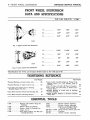
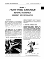
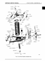
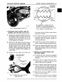
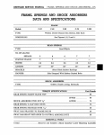
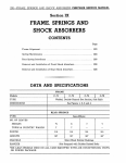
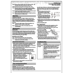
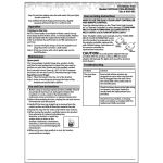
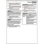
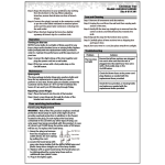
Section I
FRONT WHEEL SUSPENSION
SERVICE BULLETIN REFERENCE
NUMBER
DATE
SUBJECT
CHANGES
CHRYSLER SERVICE MANUAL
8—FRONT WHEEL SUSPENSION
FRONT WHEEL SUSPENSION
DATA AND SPECIFICATIONS
C-67, C-68 C-69, C-70
C-300
A
7.24"
7.24"
7.24"
B.
1.60"
1.60"
1.60"
C.
3.12"
3.12"
3.12"
A
11.56"
*11.68"
11.56"
B.
1.68"
1.74"
1.68"
C.
.90"
.90"
.90"
D,
.94"
1.03"
.94"
E.
3.12"
3.32"
3.12"
54x696
Fig. 1—Upper Control Arm Dimensions
54x697
Fig. 2—Lower Control Arm Dimensions
* Specifications for Town and Country Models same as for C-69 and C-70
TIGHTENING REFERENCE
Foot-Pounds
Threaded Bushing on Lower Control Arm
180
Threaded Bushings on Upper Control Arm
130
Upper and Lower Control Arm to Steering
Knuckle Support Pin Nut
100
Upper Shock Absorber Piston Rod Mounting Nut.
35
Lower Shock Absorber Mounting Bracket
60
Foot-Pounds
Upper Control Arm Pivot Bars to Frame Crossmember Bolts C-67, C-68 (Except Town &
Country)
80
C-69, C-70 (Also C-67 and C-68 Town & Country). 110
Lower Control Arm Pivot Bars to Frame Crossmember Bolts
60
Threaded Bushing in Lower End of Steering
Knuckle Support
180
Steering Knuckle Support to Eccentric Bushing
Clamp Bolt
40
ESSENTIAL TOOLS
C-328
C-369
C-630
C-695
C-736
Remover and Installer—King Pin
Bushings
Reamer—King Pin Bushing
Reamer—King Pin Bushing Line
Gauge—Toe-In
Tool—Upper Control Arm Seal and
Bushing Installing
C-829
C-830
C-3413
Wrench—Camber Adjusting
Wrench—Camber Adjusting
Remover and Installer—Shock
Absorber Lower Mounting
DD-428 or C-3409.. Gauge—Caster, Camber, and K.P.I.
DD-435
Turntable
MT-269
Wrench—Camber Adjusting
FRONT WHEEL SUSPENSION—9
CHRYSLER SERVICE MANUAL
Section I
FRONT
SUSPENSION
REMOVAL DISASSEMBLY,
ASSEMBLY AND INSTALLATION
1. DESCRIPTION
The front crossmember of the front suspension
system on the 1955 cars has been redesigned
and strengthened with heavier gauge steel, to
increase frame rigidity and resistance to road
shock, allowing for an increase in front wheel
track, lower center of gravity and improving
the front suspension system in general, as shown
in Figure 5.
Also changed in the new front suspension
system assembly is the manner in which the
upper control arm pivot bar is attached to the
front crossmember (Fig. 3). In the new design,
the bar is attached to the crossmember with two
bolts instead of four, as formerly. The upper
and lower control arm dimensions and the front
spring heights are also changed.
The front shock absorbers are mounted in
rubber mountings within the coil spring on the
new frame, as shown in Figure 4, permitting
better shock absorber action and improved front
end control.
2. LUBRICATING SUSPENSION PARTS
Lubrication should never be neglected when
assembling suspension parts. Parts, such as
rubber seals, seal plugs, bushings and bearings,
should be properly located and installed to insure
proper lubrication. When assembling coil springs
to front crossmember and lower control arms,
the coil spring should be centered and located in
position before assembly. Pivot bars should also
be centered in upper and lower control arms to
facilitate adjustment and lubrication. Suitable
provisions have been made in the design of suspension parts to allow for proper lubricating
of moving parts. The Lubrication Section of
this manual should be consulted for correct lubricating procedures.
SCREW
55P1014
Fig. 3—Upper Control Arm Pivot Bar Installed
Fig. 4—Front Shock Absorber Installation
10—FRONT WHEEL SUSPENSION
CHRYSLER SERVICE MANUAL
D
CO
IX.
Jl
O>
FRONT WHEEL SUSPENSION—11
CHRYSLER SERVICE MANUAL
•NUT
BUSHING
•O
WASHER
$*m
SCREW
FITTING
BUSHING
PLUG
BEARING
LOCK PIN
LOCKWASHER
FITTING
BUSHING
SHOCK ABSORBER
MOUNTING
LOCKWASHER55x4
Fig. 6—Front Wheel Suspension (Exploded View)
12—FRONT WHEEL SUSPENSION
CHRYSLER SERVICE MANUAL
SERVICE PROCEDURES
3. REMOVAL AND DISASSEMBLY OF UPPER
CONTROL ARM (Refer to Fig. 6)
It is recommended in the event of damage to
the upper or lower control arm, or pivot bars,
that a complete upper or lower control arm assembly be installed. A new support arm pivot
bar or bushing can be installed, however, if
necessary.
Basically, the upper control arm remains the
same as those used in previous models (Figs. 1,2);
however, it is approximately *4 inch wider and
is mounted to the frame with two bolts instead
of four. Due to these changes, the method of
centering the pivot bar is somewhat different
in that we can no longer use Tool C-608 for locating the center. It can be used to maintain the
set dimension of the upper control arm when
new pivot bar bushings are installed.
4. REMOVAL OF UPPER CONTROL ARM
(See Fig. 7)
(1) Raise the hood and remove dirt or grease
from around the shock absorber upper
mounting area.
(2) Raise car by placing a jack or support under the lower control arm.
(3) Remove front wheel and tire assembly.
(4) Loosen locking screw and remove upper
control arm to knuckle support pin.
(5) Remove pivot arm attaching bolts and remove upper control arm.
(6) Clean parts thoroughly in a suitable solvent and blow dry with compressed air.
(7) Pivot bar, bushings, pin, seal and threaded
section of control arm must be thoroughly
inspected for wear. Replace parts as
necessary.
NOTE
It is recommended in the event of damage to the
upper or lower control arm or the replacement
of a steering knuckle support arm, that the caster and camber be checked and brought up to
specified limits listed in Data and Specifications.
5. ASSEMBLY OF UPPER CONTROL ARM
The upper control arm pivot bar bushings are
of the self-threading type. When installing a
new upper control arm, use new pivot bar bushings. To assemble the upper control arm, pivot
and bushings properly, use special Tool C-608
to maintain the proper spread dimension of the
control arm which will also assist in relieving
thread tension after the bushings have been
started.
(1) Center the pivot bar bushing with dust
seals installed in the control arm and install Tool C-608 on the pivot bar.
(2) Expand the two jaws of the tool by tightening the expander wedge screw until the
jaws of the tool are just snug against the
inside of the control arm. Do not bring the
screw down more than is necessary to
place the jaws firmly against the control
arm to maintain a fixed dimension of 714
inches at the outside of the "horns" of the
control arm (see dimension "A", Fig. 1)
when new pivot bar, bushings, etc. are installed.
CAUTION
To avoid tool interference with bushings make
sure jaivs of tool are seated against inside face
of control arm and not against the arm flange.
(3) Clamp tool and control arm assembly in
vise. Center pivot bar. Lubricate bushings
with suitable lubricant.
(4) Start bushings on both ends of the pivot bar.
Thread the bushings into each side of the
control arm until the shoulders of the bushings contact the surface of the control arm.
Tighten to 130 foot-pounds torque.
(5) Remove the tool and check the operation of
the pivot bar for free movement (only a
moderate grip should be required to turn
the pivot bar).
CAUTION
The pivot bar may be rotated one turn in either
direction to obtain correct centering position.
FRONT WHEEL SUSPENSION—13
CHRYSLER SERVICE MANUAL
NECESSARY
CLEARANCE
BUSHING
N O CLEARANCE ON WORKING SIDE OF PIN
55x75\
Fig. 7—Removing Upper Control Arm
IN BUSHING- "V" THREAD DESIGN PREVENTS END
PLAY OF PIN WHEN UNDER NORMAL LOAD
Fig. 9—Diagram of Threaded Bushing
6. INSTALLING UPPER CONTROL ARM, PIN,
BUSHING, AND DUST SEAL (Refer to Fig. 8)
(1) Install a new eccentric bushing in the steering knuckle support and place one seal on
the bushing at the hexagonal end of the
bushing, and the other seal on round boss
of the support arm bushing.
(2) With Tool C-736, depress the outer edge or
lip of the seal, as shown in Figure 8. Slide
the control arm and seal onto the steering
knuckle support unit until the seal fits
properly over the bushing and the pin hole
is in proper alignment with bushing and
control arm.
(3) Remove tool and install the control arm
SEAL AND BUSHING
INSTALLING TOOL
STEERING KNUCKLE
SUPPORT
pin washer and nut. Position upper control
arm pivot on frame.
(4) Use a drift to line up pivot bar holes with
the frame crossmember holes. Install the
attaching bolts and tighten securely to
torque specifications.
(5) Install front wheels and tire assembly. Inspect or replace damaged greasing fittings.
(6) Lower car, remove jack, check front wheel
caster and camber. Tighten control arm
locking pin and support arm screw to torque
specifications.
7. REMOVAL OF LOWER CONTROL ARM
AND FRONT SPRING
(1) To remove the lower control arm assembly
and front spring, remove the front shock
absorber.
(2) Place a jack or support under the lower
control arm to be removed, raise car and
remove wheel and tire assembly.
(3) Place a support under frame near the upsweep at the front of frame. Support the
lower control arm and front spring and remove the control arm and knuckle support
pin, lock nut and washer and remove pin.
(4) Raise front end of car slightly to relieve
pressure on front spring.
Fig. 8—Installing Upper Control Arm Pin
Bushing Dust Seal
(5) Remove front sway-bar from attaching
bolts. When pressure is off front spring,
14—FRONT WHEEL SUSPENSION
CHRYSLER SERVICE MANUAL
BOLT
• CUSHION RETAINER
CUSHION
LOCKWASHER
\
NUT
SWAY ELIMINATOR
SHAFT ASSEMBLY
CUSHION RETAINER
BOLT
'P""V
-cf
KJ 49x901 A
Fig. 10—Sway Bar (Exploded View)
remove jack or support which was placed
under control arm, swing arm down and
remove front spring. The control arm can
then be removed by removing frame to
support bar attaching bolts.
8. SWAY ELIMINATOR
The sway eliminator, as shown in Figure 10, requires no adjusting other than periodical tightening of fastening bolts.
The rubber-cored bushings must not be
lubricated or allowed to come in contact with
grease or oil.
9. INSTALLATION OF LOWER CONTROL ARM
When replacing the lower control arm assembly,
always use new pivot bar bushings and dust
seals. The lower control arm pivot bar mounting
bolt locations have been changed. For this reason
the method of centering the lower pivot bar has
been changed. Due to the location of these
mounting holes, Tool C-594 cannot be used for
centering the lower pivot bar, but can only be
used to maintain the set dimension of the con-
trol arm. (See Fig. 2 for dimensions when installing a new pivot bar.) To replace pivot bar
proceed as follows:
(1) Install dust seals on pivot bar and position
pivot bar in the control arm. Assemble Tool
C-594 to the pivot bar.
(2) Install dust seals on pivot bar and clamp
lower control arm in vise, with steering
knuckle support down on bench. Center
pivot bar in control arm, lubricate bushings
with a suitable lubricant and start bushing
evenly on both ends of pivot bar.
(3) Remove locating studs from Tool C-594 and
place tool in position on pivot bar (open
ends of tool down) on bench. Making sure
tool remains in place, thread the bushing
(one to your right) into control arm until
the shoulder of the bushing contacts machined surface of control arm. Tighten to
180 foot-pounds torque.
(4) Remove tool from assembly and reverse
position of assembly in vise (top of spring
seat up on bench). Re-position Tool C-594
CHRYSLER SERVICE MANUAL
on pivot bar and thread remaining bushing
into control arm using same torque. Remove
tool and assembly from vise and check pivot
bar for free movement.
NOTE
Pivot bar may be rotated one turn in either
direction to obtain correct centering position.
(5) Place the front spring on end in the lower
control arm spring seat (flat end up). Lay
the upper silencer on top of the spring, and
install lower silencer (if so equipped). Install spring and upper silencer in the frame
crossmember, turn the spring until it indexes with the lower spring seat and bring
lower control arm up to hold it in position.
NOTE
Look up through the spring, using a bright light,
to see if the upper end of the spring is positioned
FRONT WHEEL SUSPENSION—15
correctly in front crossmember. Also determine
(by feel) if the lower end of the spring is in
position.
(6) Install jack under the spring seat and jack
up the lower control arm until the pivot bar
attaching bolts can be installed, then tighten
bolts securely.
(7) Install the front shock absorber, as described in Shock Absorber Section of this
manual.
(8) Install sway-bar.
(9) Install wheel and tire assembly.
NOTE
It is recommended in the event of damage to the
upper or lower control arm or the replacement of
a steering knuckle support arm, that the caster
and camber be checked and brought up to specified limits listed in Specifications.
SERVICE DIAGNOSIS
10. FRONT END NOISY
Possible Causes:
a. Improper lubrication
b. Looseness in front suspension
c. Front shock absorber noisy
d. Sway eliminator noisy
Remedies:
a. Lubricate car.
b. A certain amount of looseness is designed
into the threaded bushings of the front suspension linkage to prevent binding of the joints
under deflection. Unless they cause noise or unstable steering, these parts should not be replaced. Proper lubrication is essential, however.
It should be remembered that threaded bushings
require more clearance than a smooth pin and
bushing type joint; actually, only the "knifeedge" of the threaded pin operates in the "V"
shaped thread cut in the bushing, as shown in
Figure 9. With the weight of the car on the
bushings, the knife-edge bears against the "V"
until there is sufficient wear to permit endwise
movement of the threaded pin in the bushing.
This condition will cause no harmful effect except an increase in noise on rough roads. Always
recheck front wheel alignment after repairs are
made.
c. The rubber bushings on which the shock
absorbers are mounted to the anchor studs may
be worn and noisy, in which case, it is necessary
to replace only the bushings.
Shock absorbers which have been found to be
noisy should be replaced with new ones. The
shock absorbers are of the "spun-over" type and
are not serviceable.
d. The sway eliminator shaft requires no adjusting other than periodic tightening of the
fastening bolts.
The rubber bushings on the springs, shock
absorbers and sway eliminator shaft must not be
lubricated or allowed to come in contact with
any form of mineral oil. Mineral base oils will
cause rapid deterioration of natural rubber.