1
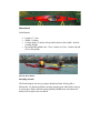
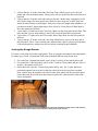
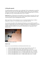
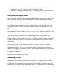
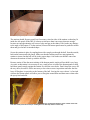
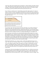
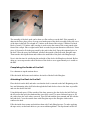
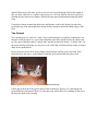
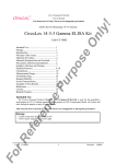
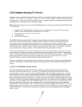
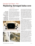
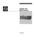
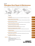
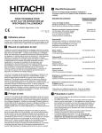
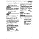
The Point Bennett Sea Kayak Designed by Duane Strosaker Model Name The Point Bennett is named after the westernmost point on San Miguel Island. The point takes the brunt of the NW wind and swell in Southern California, and waves break over the many reefs surrounding it. It is the most challenging point to round in the region. Design The Point Bennett is designed to track well in wind and waves, carve edged turns, and paddle fast. The rocker is moderate at the bow and minimal at the stern to reduce weather cocking and broaching. The chine is fairly low with minimal upsweep to help carve edged turns. Moderate fullness in the bow and more in the stern increases the effective waterline length to reduce resistance at high speeds. Dimensions Point Bennett Length: 17½ feet Width: 21 inches Cockpit depth: 12 inches in front and 8 inches in back (add 1 inch for coaming height) Recommended paddler size: 5 feet, 6 inches to 6 feet, 2 inches tall and 150 to 200 pounds Point Bennett next to CD Gulfstream in Newport Harbor, California. Photo by Victor Martin. Carrying a Load The Point Bennett can carry a properly distributed load. Packing like a backpacker, I've had no problems carrying camping gear and food for trips up to seven days. With a load the kayak generally handles best with about twothirds of the weight in the rear hatch. Cabrillo Beach, California. Photo by Dave O'Connor. Point Bennett Accomplishments Bay2Bay 20 Mile Race in 03:20:55 in 2004. Catalina Island crossings and circumnavigation in 2004. Catalina Island crossings and circumnavigation in 2005. San Miguel Island circumnavigation and crossings to Wilson Rock and Richardson Rock in 2004. Catalina for Lunch Crossings, 2004, 2005, 2006, 2007 and 2009. Anacapa Island crossings and circumnavigation in 2005. Catalina Island crossings and West End circumnavigation in 2006. Catalina Island crossings in 2007. San Miguel Island circumnavigation in 2007.. Catalina Island crossings in 2008.. Catalina Island crossings and circumnavigation in 2009. Anacapa Island and Santa Cruz Island crossings in 2009.. Crossed to All 23 Southern California Offshore Oil Rigs in 2010. Survived Great White Shark Attack in 2010. Greenland Week Champion 2010. Laguna Beach, California. Photo by Victor Martin. Building the Point Bennett The instructions for building the Point Bennett are below. You may use the instructions to build your own kayak for non-commercial purposes. Building the Point Bennett by Duane Strosaker Special Note These building instructions are intended for people who: 1. Read The New Kayak Shop by Chris Kulczycki and The Strip-Built Sea Kayak by Nick Schade. 2. Read and studied the user manual for the brand of epoxy being used. 3. Agree to build and paddle the Point Bennett at their own risk. You may use these instructions to build your own kayak for non-commercial purposes. Rough Cutting the Panels Cut from 4 sheets of 8 foot by 4 foot marine grade 4 mm Okoume plywood: 1. 8 pieces that are 11 inches wide and 8 feet long. Four of these pieces are for the side panels and 4 for the bottom panels. These pieces will use up the first and second sheets of plywood. 2. 2 pieces that are 12 inches wide and exactly 6 feet and 3 inches long. Lengthwise (6 feet and 3 inches long), the center panels are a final cut, not a rough cut, so these final cuts should be made cleanly at right angles. Each piece needs one straight edge lengthwise, so cut them out at the 2 long straight edges of the 8 foot by 4 foot plywood. Mark them as the center panels for the deck. 3. 1 piece that is 22 inches wide and 7 feet long. Mark it as the stern panel for the deck. This piece and the 2 pieces from number 2 above will use up the third sheet of plywood. 4. 1 piece that is 17 inches wide and 5 feet and 6 inches long. Mark it as the bow panel for the deck. 5. 2 pieces that are 11 inches wide and 2 feet long. Mark these 2 pieces as the bow end of the side panels. These 2 piece and the piece from number 4 above will use the forth sheet of plywood and leave enough extra for the cockpit coaming lip and bulkheads. Joining the Rough Panels Use butt or scarf joints to join the rough panels. There is enough extra length in the rough panels for either type of joint. I recommend scarf joints in the hull and butt joints in the deck. 1. For each of the 2 bottom hull panels, join 2 of the 11 inch by 8 foot panels end to end. 2. For each of the 2 side hull panels, join 2 of the 11 inch by 8 foot panels and one of the 11 inch by 2 foot panels end to end. 3. On the deck don’t join the 2 center deck panels side by side. The 2 center panels are positioned together but not joined so that the center deck can be raised into a peaked deck. Join the bow deck panel to one end of center deck panels and the stern deck panel to the other end. Be sure the bow and stern deck panels are centered on the ends of the center deck panels. From left to right, the deck, 2 bottom panels, and 2 side panels. The weights are being used to hold down the backing plates for butt joints while the epoxy hardens. Scarf joints can be used too. Lofting the panels The lofting numbers for the panels are easy to understand. From a starting point on a panel, the numbers tell you how far to go to the right, and then from there, how far to go up or down for each point. For example, one of the lines for lofting the bottom hull panels reads, “At 5 feet to the right the keel is up 1/8 inches and the chine is up 8 1/16 inches.” Important! Some of the panels are measured bow to stern, and others, stern to bow. Be sure to check the direction being measured, especially with the bottom panels, and mark the bow and stern on the panels to prevent installing them backwards. Make sure the lines are fair, meaning the curves are smooth and without bulges or hallows. Being off by as little as 1/32 of an inch can cause a noticeably unfair line. Try your best to keep the keel line in the bottom hull panels as accurate and fair as possible. Because the bottom panels meet at a shallow angle, any unfairness is compounded here, resulting in bulges or hollows along the keel line. It is difficult to get the keel line of the bottom hull panels perfectly fair, but don’t worry, because I will tell you how to compensate for any unfairness later. A batten being used to loft the deck. Side Panels Measure bow to stern with the sheer on the bottom and the chine on top. At 0 feet to the right the sheer starts (bow) up 0 inches and there is no chine yet. At 1 foot to the right the sheer is up 3/4 inches and there is no chine yet. At 1 foot and 3 inches to the right skip sheer and the chine starts up 8 11/16 inches. At 2 feet to the right the sheer is up 1 5/16 inches and the chine is up 9 1/16 inches. At 3 feet to the right the sheer is up 1 19/32 inches and the chine is up 9 5/16 inches. At 4 feet to the right the sheer is up 1 3/4 inches and the chine is up 9 5/16 inches. At 5 feet to the right the sheer is up 1 3/4 inches and the chine is up 9 1/4 inches. At 6 feet to the right the sheer is up 1 5/8 inches and the chine is up 9 3/32 inches. At 7 feet to the right the sheer is up 1 1/2 inches and the chine is up 8 15/16 inches. At 8 feet to the right the sheer is up 1 7/16 inches and the chine is up 8 3/4 inches. At 9 feet to the right the sheer is up 1 7/16 inches and the chine is up 8 19/32 inches. At 10 feet to the right the sheer is up 1 7/16 inches and the chine is up 8 7/16 inches. At 11 feet to the right the sheer is up 1 1/2 inches and the chine is up 8 1/4 inches. At 12 feet to the right the sheer is up 1 9/16 inches and the chine is up 8 1/16 inches. At 13 feet to the right the sheer is up 1 5/8 inches and the chine is up 7 29/32 inches. At 14 feet to the right the sheer is up 1 11/16 inches and the chine is up 7 11/16 inches. At 15 feet to the right the sheer is up 1 21/32 inches and the chine is up 7 7/16 inches. At 16 feet to the right the sheer is up 1 5/16 inches and the chine is up 7 inches. At 16 feet and 9 3/16 inches to the right skip the sheer and the chine ends up 6 1/2 inches. At 17 feet to the right the sheer is up 9/16 inches and there is no chine. At 17 feet and 7 1/4 inches to the right the sheer ends (stern) up 0 inches and there is no chine. Bottom Panels Measure stern to bow with the keel on the bottom and the chine on top. At 0 feet to the right skip the keel and the chine starts (stern) up 2 9/16 inches. Be sure to mark this end as the stern. At 4 7/16 inches to the right the keel starts up 1/8 inches and skip the chine. At 1 foot to the right the keel is up 7/32 inches and the chine is up 3 1/4 inches. At 2 feet to the right the keel is up 7/32 inches and the chine is up 4 7/16 inches. At 3 feet to the right the keel is up 3/16 inches and the chine is up 5 13/16 inches. At 4 feet to the right the keel is up 5/32 inches and the chine is up 7 1/16 inches. At 5 feet to the right the keel is up 1/8 inches and the chine is up 8 3/32 inches. At 6 feet to the right the keel is up 3/32 inches and the chine is up 8 13/16 inches. At 7 feet to the right the keel is up 1/16 inches and the chine is up 9 inches. At 8 feet to the right the keel is up 1/16 inches and the chine is up 8 13/16 inches. At 9 feet to the right the keel is up 1/16 inches and the chine is up 8 3/8 inches. At 10 feet to the right the keel is up 1/16 inches and the chine is up 7 5/8 inches. At 11 feet to the right the keel is up 1/16 inches and the chine is up 6 21/32 inches. At 12 feet to the right the keel is up 1/16 inches and the chine is up 5 7/16 inches. At 13 feet to the right the keel is up 1/16 inches and the chine is up 4 9/32 inches. At 14 feet to the right the keel is up 1/16 inches and the chine is up 3 5/16 inches. At 15 feet to the right skip the keel and the chine is up 2 25/32 inches. At 15 feet and 15/16 inches to the right the keel ends up 0 inches and skip the chine. At 15 feet and 6 3/16 inches to the right skip the keel and the chine ends (bow) up 2 25/32 inches. Be sure to mark this end as the bow. Deck Panel Measure stern to bow, beginning on the stern panel and centered exactly 6 feet and 8 inches behind where the center panels meet the stern panel. At 0 feet to the right (stern) go up and down 0 inches. At 1 foot to the right go up and down 2 inches. At 2 feet to the right go up and down 3 15/16 inches. At 3 feet to the right go up and down 5 11/16 inches. At 4 feet to the right go up and down 7 1/4 inches. At 5 feet to the right go up and down 8 9/16 inches. At 6 feet to the right go up and down 9 9/16 inches. At 7 feet to the right go up and down 10 3/16 inches. At 8 feet to the right go up and down 10 7/16 inches. At 9 feet to the right go up and down 10 1/4 inches. At 10 feet to the right go up and down 9 3/4 inches. At 11 feet to the right go up and down 8 7/8 inches. At 12 feet to the right go up and down 7 13/16 inches. At 13 feet to the right go up and down 6 5/8 inches. At 14 feet to the right go up and down 5 1/4 inches. At 15 feet to the right go up and down 3 3/4 inches. At 16 feet to the right go up and down 2 1/4 inches. At 17 feet and 5 5/8 inches (bow) go up and down 0 inches. Paddler/Cockpit Location In the proper paddling position (sitting straight up or slightly forward), the paddler’s lower back must be exactly 7 feet forward of the stern. Any variation in the location of the paddler will alter the intended performance of the kayak. Generally, it is best to have 4 inches between the paddler's lower back and the back of the cockpit. As a result, the back of my cockpit is 6 feet and 8 inches forward of the stern. Stations Stations are absolutely necessary to help shape the hull. Using the lofting numbers, draw and cut out the stations from 1/2 inch hardwood plywood. Lofting the stations is similar to the panels, but with the stations the measuring begins at the keel, and then you are told how far to go up and to each side for the chine and sheer. When drawing the stations, be sure to include a vertical center line to help with checking the alignment of the hull. Station #1: From the keel, the chine is up 2 5/16 inches and left and right 3 1/4 inches, and the sheer is up 9 5/8 inches and left and right 5 1/4 inches. Station #2: From the keel, the chine is up 1 13/16 inches and left and right 7 1/8 inches, and the sheer is up 9 inches and left and right 8 7/8 inches. Station #3: From the keel, the chine is up 1 3/8 inches and left and right 8 13/16 inches, and the sheer is up 8 3/16 inches and left and right 10 7/16 inches. Station #4: From the keel, the chine is up 1 9/16 inches and left and right 7 1/16 inches, and the sheer is up 7 11/16 inches and left and right 8 9/16 inches. Station #5: From the keel, the chine is up 1 13/16 inches and left and right 4 1/8 inches, and the sheer is up 7 1/2 inches and left and right 5 11/16 inches. Cutting and planing the panels Before cutting the 2 side and 2 bottom hull panels, attach the pairs to each other so that the work can be reduced by half and the pairs are better matched. The pairs can be attached with nails, screws, or staples. Use a jigsaw to cut just outside the lines, and then use a plane to go down to the line. Along the last 12 inches at the bow and stern tips of the deck, leave about 1/8 of an inch of extra wood around the lofted lines so that fine trimming can be done later to better match the deck to the hull. Check the lines on panels for fairness. If they are not fair, don’t be afraid to use the plane a little to make them fair. Again, try your best to keep the keel line in the bottom hull panels as accurate and fair as possible. Because the bottom panels meet at a shallow angle, any unfairness is compounded here, resulting in bulges or hollows along the keel line. It is difficult to get the keel line of the bottom hull panels perfectly fair, but don’t worry, because I will tell you how to compensate for any unfairness later. Before detaching the pairs of bottom and side panels, drill some of the holes for the wires. Drilling the holes through the pairs will allow the holes to match evenly on each side of the stems and along the keel. Also, it is easier to drill the chine holes on the bottom panels now rather than when the hull is assembled. However, some of the drilling will have to wait until the hull is assembled. Drill the holes around the entire perimeter of the bottom panels and only along the stems of the side panels. Detach the pairs of bottom and side panels. Assembling the Hull With the inside of the bottom panels facing each other flat, use 18 gauge copper wire to first snugly attach the bow and stern stems. Loosely wire the keel so that there enough slack to pull the chines apart. Pull the chines of the bottom panels apart to get the approximate shape of the finished hull. Use duct tape to help hold down the chines. Use scraps of wood to evenly support the bottom panels as necessary. The bottom panels wired together. With the inside of the side panels facing each other, snugly wire the bow and stern stems. Place the side panels on top of the bottom panels. Line up the bow edge of the side panels with the bow edge of the bottom panels. It is easy to mix up the bow and stern ends of the bottom panels, so check where you marked the bow and stern to make sure the bottom panels are not installed backwards. From the bow, drill holes along the chine of the side panels near the bow to match the holes already drilled along the chine of the bottom panels. As you drill a hole, wire it, alternating the sides of the hull to keep the wiring even as you go along. The side panels wired to the bottom panels at the bow. Each station is installed after the chines are wired about one foot past the station location. Install the stations in their numerical order, meaning station #1 first and #5 last. From the bow of the hull, station #1 is 3 feet and 6 inches back, station #2 is 6 feet and 6 inches back, station #3 is 9 feet and 6 inches back, station #4 is 12 feet and 6 inches back, and station #5 is 14 feet and 6 inches back. Stations helping to shape the hull. The stations should fit pretty good, but if necessary, trim the sides of the stations so that they fit inside the side panels of the hull. It is better to trim more than is necessary than not enough, because not enough trimming will cause a bulge and gap at the chines. Don’t make any changes to the angle of the bottom V on the stations, because the bottom panels must be pushed to match them and give the hull its intended shape. Secure the stations in place by stapling them with a staple gun through the hull, from the outside, both on the bottom and side panels. Make sure that the bottom panels are snug against the stations to insure that the hull will be in the proper shape. Also make sure that the center line drawn on the stations is lined up with the keel line. Because station #5 has the most twisting of the bottom panels, staples will not hold it very long. As result, at this station it is necessary to use a small screw on each of the bottom panels to help hold these panels snugly against the station. Pre-drill the screw holes. Don’t fasten the screws all the way down, because it will be necessary to leave these screws in position until after the first layer of fiberglass is epoxied over the bottom of the hull. Leaving the screws about ¼ of an inch out from the bottom panels will allow you to fiberglass around them and then remove them after the epoxy has hardened. The screws used to hold station #5 until after the first layer of fiberglass hardens on the outside of the hull. Note that in this photo the first layer of fiberglass is on the hull, which is a later step. At the stem of the stern, the bottom panels extend about 1/2 inch beyond the side panels. In other words, when the bottom and side panels match perfectly at the bow, the bottom panels will stick out about 1/2 inch past the side panels at the stern. The reason for the extra 1/2 each is to allow for trimming to precisely match the bottom and side panel stems at the stern. Now is the time to trim this extra 1/2 inch off the stern end of the bottom panels. To avoid over cutting, it is better to not quite cut enough off and then file it down the rest of the way. Remove wires as necessary as you cut, and where the wires have been removed, use spring clamps to hold the bottom panel stems together. Once the trimming is complete, drill new holes and re-wire the the panels at the stem. Now comes the most critical part of plywood kayak construction. It is extremely important to sight down the chines, and especially the keel, to make sure that the lines are fair or straight. These lines can be checked most accurately with the hull upside down. Look for hollows, bulges and hooks, especially in the keel. Now is the best time for any adjustments to correct the lines. If the lines are not fair or straight, first check to see that the panel edges are even against each other. If necessary, loosen some wires, push and pull the panels until the edeges are even, and then retighten the wires. Along the keel you may need to tighten the stitches in the area of bulges and loosen the stitches in the area of hallows. Small wedges of wood in the seam help to remove larger hallows. It is OK to have small gaps between the panels to avoid hollows. Any gaps can be well reinforced later with fiberglass. Also, make sure that the kayak is not twisted. With the hull right side up, sight along the vertical lines on the stations and the bow and stern stems to make sure they line up. If necessary, twist the hull to get them straight. With the hull upside down, use a syringe to apply a small amount unthickened epoxy to the seams. This step is not for filleting. Instead, it is for securing the hull panels together so that the wires can be pulled out and the outside of the hull can be reinforced with fiberglass while the stations are still holding the shape of the hull. With the hull right side up, use a bead of wood glue to secure the edges of the stations to the panels, so that the staples (not the screws at station #5) can be removed soon. Don’t use a lot of glue on the stations, because they will have to be removed later. After the epoxy in the seams has hardened, carefully pull out the wires, which are not necessary now that the seams are epoxied. With the wires removed, it is easier to sight along the seams to check again that the lines are fair or straight. If a line is bothering you, use a razor knife to cut through the epoxy in the seam and rework it. This is your last chance to make any changes. Once you are satisfied with the lines, fill the outside seams with thickened epoxy, and after it has hardened, file and sand the outsides seams smooth. Reinforce the outside of the hull with fiberglass as desired. After the epoxy has hardened in the first layer of fiberglass, it is safe to remove the screws on the bottom panels at station #5. Fill the screw holes with thickened epoxy. Try to avoid getting the thickened epoxy all of the way down into the station to make removing the station easier later. Add additional layers of fiberglass as desired. Leave the stations in place to help keep the shape of the hull while you assemble the deck. Assembling the Deck From scrap plywood, make a template for a cockpit that is the size and shape as desired. The template is used for the marking the inside line of the cockpit on the deck, and later the cockpit coaming spacer and lip. My cockpit template. Use the cockpit template to draw the inside line for the cockpit on the deck. When positioning the cockpit on the deck, it is important to keep in mind that in the proper paddling position (sitting straight up or slightly forward), the paddler’s lower back must be exactly 7 feet forward of the stern tip on the deck. Any variation in the location of the paddler will change the intended performance of the kayak. Generally, it is best to have 4 inches between the paddler's lower back and the back of the cockpit. As a result, the back of my cockpit is 6 feet and 8 inches forward of the stern tip. Cut just inside the cockpit line on the deck to allow for trimming down to the cockpit coaming when it is attached later. You may also want to leave thigh braces when cutting the cockpit on the deck. The deck area on the center panels in front of the cockpit is peaked. This peak is formed by pulling up the center of the 2 center panels at the front of the cockpit and filling the gap formed in the peaked deck with a strip of 4 mm plywood that is trimmed to fit. The peaked deck. The assembly of the deck peak can be done on a flat surface or on the hull. If the assembly is done on the floor, place pieces of scrap wood under parts of the deck to roughly follow the curve of the sheer in the hull. For a depth of 12 inches at the front of the cockpit, a finished 2x4 inch block of wood (3 3/8 inches wide) on edge is used to raise the center of the center panels at the front of the cockpit. Place weights on the deck as needed to prevent distortion of the deck. Trim a piece of plywood to fit in the gap caused by the peak in the deck. Epoxy this trimmed piece in the deck. Once the epoxy has hardened, reinforce the topside of the peak with fiberglass tape. Then turn the deck upside down and reinforce the underside of the peak with fiberglass tape. Now is also the time for reinforcing the underside of the deck with fiberglass as desired. Before doing so, use scraps wood to allow the sheer of the deck to curve approximately as it would on the hull. Completing the Inside of the Hull Use a hammer to tap the stations loose. Fillet the inside hull seams and reinforce the inside of the hull with fiberglass. Attaching the Deck to the Hull Place the deck on the hull, and make sure that the deck is centered on the hull. Beginning at the bow and alternating sides, drill holes through the hull and deck as close to the sheer as possible and wire the deck to the hull. Using thickened epoxy, fill the outside of the sheer seams to glue the deck to the hull. Pull out the wires after the epoxy has hardened but is not fully cured. Use more thickened epoxy to fill the voids where the wires where removed. Then file and sand the sheer smooth and fair with the hull and deck. Cover the outside sheer with fiberglass tape or the fiberglass cloth used to reinforce the deck. Fillet the inside sheer seams and reinforce them with 2 inch fiberglass tape. To make applying the tape easier, cut the hatch holes so you can reach through them. The tape doesn't need to be applied all the way to the ends. As far as you can reach is good enough. Roll up the length of tape you need, and soak it is a plastic cup of epoxy to wet it out. Remove the excess epoxy by drawing the tape between two fingers. Roll up the tape again and then unroll along the inside seam. Using sheer clamps to attach the deck to the hull doesn't work for this design, because they prevent the top of the side panels from being flexible enough to match the outline shape of the deck. The Cockpit The coaming spacer is cut from ¾ inch, 5 layer, hardwood plywood, and the coaming lip is cut from the 4 mm plywood. Use your cockpit template to draw the inside lines for the spacer and lip. The spacer should be about ¾ inches wide, and the lip should be about 1 ¾ inches wide. Cut the spacer and lip so that they are one piece each, with a thin cut down the front center of each to allow for the peaked deck. Epoxy the spacer to the deck, using clamps to hold it down until the epoxy has cured. Then epoxy the lip to the spacer, using clamps to hold the lip down until the epoxy has cured. Note the gap in the front of the coaming. It will be filled in a later step. Fill the gap at the front of the spacer and lip with a trimmed to fit piece of ¾ inch hardwood plywood and several trimmed layers of 4 mm plywood, which allow for rounding off the top of the lip at the front of the coaming. The filled gap in the front of the coaming. Reinforce the coaming with fiberglass as desired. Copyright 2004-2013, Duane Strosaker. All rights reserved.