1
US 20130194629A1
(19)
United States
(12) Patent Application Publication (10) Pub. No.: US 2013/0194629 A1
Kojima
(43) Pub. Date:
Aug. 1, 2013
(54)
Publication Classi?cation
IMAGE FORMING APPARATUS, METHOD
FOR CONTROLLING IMAGE FORMING
APPARATUS, AND STORAGE MEDIUM FOR
PERFORMING MAINTENANCE ON AN
IMAGE FORMING APPARATUS
(51)
Int. Cl.
H04N 1/00
(52) US. Cl.
(2006.01)
CPC ............................... .. H04N1/00413 (2013.01)
(71) Applicant: CANON KABUSHIKI KAISHA,
Tokyo (JP)
USPC
nance item for a user to do maintenance includes an input unit
con?gured to input code information for specifying a plural
ity of maintenance items to be displayed by the image form
ing apparatus, a specifying unit con?gured to specify the
plurality of maintenance items to be displayed by the image
(73) Assignee: CANON KABUSHIKI KAISHA,
Tokyo (JP)
(21) Appl. No.: 13/748,348
Filed:
forming apparatus out of all the maintenance items based on
the code information input by the input unit, a generation unit
Jan. 23, 2013
con?gured to generate a screen for displaying the plurality of
maintenance items speci?ed by the specifying unit on the
Foreign Application Priority Data
(30)
358/115
(57)
ABSTRACT
An image forming apparatus con?gured to display a mainte
(72) Inventor: Nobuyuki Kojima, Yokohama-shi (JP)
(22)
....................................................... ..
same screen, and a display unit con?gured to display the
Feb. 1, 2012
(JP) ............................... .. 2012-019897
screen generated by the generation unit.
m
we
WERAm-M van ....9
2
aw
iiég‘?gm"
RAM
~46
6
sesame.
.-
?RGGRA?€£ Rose;
Fatima:
-
7.
.
- gamma was?
~41
Waitress. UM“?
2
151?"? W
Av
M”
»
in
comm
,
,
{555mg
EXTERNA
.- rgtg?em'
Emmi. MEMGRY (E383) "*3
Patent Application Publication
Aug. 1, 2013 Sheet 1 0f 12
US 2013/0194629 A1
m
T6
W
mm
1%2gmEmmaa
xm$pé?8gmix
0%
w xmw:‘?)2g,w3.mE5w? w? N1, $2EswmM?i8mn3g. ,?mMWWa?,\ig;@g?awgQm
HE
\mgEN@1
m
W
EU
‘m5M
Patent Application Publication
Aug. 1, 2013 Sheet 2 0f 12
US 2013/0194629 Al
P IN. 2
5%
K‘
(W)
<3
[3
PM
(if) {5.) {:63
,
@v
<§> @
RES»?
STAR? SIG?
C3 Fix
Patent Application Publication
Aug. 1, 2013 Sheet 3 0f 12
FiGog?
3;
3;
as
<LE¥EL2>
FEEEER
GPYEQN
sgmgaR
Mi??i
maxua
5551364
\»34
aamug
US 2013/0194629 A1
Patent Application Publication
Aug. 1, 2013 Sheet 4 0f 12
HQ. 333
SENSQR___1
2i) “(3
i€§°€3~8€§°€3§
3Q“ 35mm;
SENSGR____3
SEEQSQRA
35 v
ii} A
25 mg
qmwmw
(5AM? 2i!)
{1 Zmgvwii?mg)
US 2013/0194629 A1
Patent Application Publication
Aug. 1, 2013 Sheet 5 0f 12
US 2013/0194629 A1
F311 4
E3 i SPRAY
LEVEL
SEQQEQ
LAYER
Ti? i RD
LAYER
F?URii-E
E..AYE§R
3 YEA’?
Patent Application Publication
Aug. 1, 2013 Sheet 6 0f 12
F1516. 5%
US 2013/0194629 A1
Patent Application Publication
Aug. 1, 2013 Sheet 7 0f 12
EEQF'U? CQQE
N’ 3%?
i:
EXYRACT FGRiéAT
~~¢86€32
Mk 51,593
EXE'RAQ‘F GQEBE Niiiii?iiiig
---- M36911
1
EXYRAG? EAGH HEM
1
EM}
"WSSQE
US 2013/0194629 A1
Patent Application Publication
Aug. 1, 2013 Sheet 8 0f 12
US 2013/0194629 A1
“a;m .“
N?g
35
$3
a.
$5
w
w.
W
:
N
m
q
a
.w
1.1
A”
m»
E
K
x,
mm.
3.
mwwp
\33
?g
.2.3
Q.HMM:EN
2.
“N,
Q
@M
m‘
K
MW
MN
_\.x._ >_...
?at)!“
.11>];
3
g
mg
$5M
a
g
mm
$5m
Patent Application Publication
Aug. 1, 2013 Sheet 9 0f 12
US 2013/0194629 A1
Patent Application Publication
Aug. 1, 2013 Sheet 10 0f 12
US 2013/0194629 A1
FIG, 8
(X382 NiBéEER
{WEE-:18 bits}
5H (,3 i i i i i 1 i I}
2647 (i ii i 1'? i 1?? EL‘
EYE??? (EX?E?i‘LE)
Patent Application Publication
Aug. 1, 2013 Sheet 11 0f 12
Egg;.gm?m
??u?g33a3WKmm.%mm
A
m
a
.N
“.1
11
w
.\
Wm
mm
@N.
R
ma
mm
5“.xx
US 2013/0194629 A1
Patent Application Publication
131G, 1%
Aug. 1, 2013 Sheet 12 0f 12
Q mm
F“,
US 2013/0194629 Al
'3
w 39m
“WSQQZ
a“ CHEQKSER’} mama) ----------------------------- -
EXTRAG? (B395 i‘éEMBERS
%
EXTRACT EACH HE???
EXE’RAQT GPYEQR
(I
If,‘
33%
as
/
5%
iEiSPLAY ERRGR
WFGRMATEGN
EUSPMY HEM Sa‘EREEEx?
L____
Aug. 1,2013
US 2013/0194629 A1
IMAGE FORMING APPARATUS, METHOD
if the technique discussed in Japanese Patent Application
FOR CONTROLLING IMAGE FORMING
APPARATUS, AND STORAGE MEDIUM FOR
PERFORMING MAINTENANCE ON AN
IMAGE FORMING APPARATUS
Laid-Open No. 2003-114779 is used, it takes time and labor
for the user to frequently input the search key.
BACKGROUND OF THE INVENTION
[0001]
[0002]
1. Field of the Invention
The present invention relates to maintenance of an
image forming apparatus.
[0003]
[0004]
SUMMARY OF THE INVENTION
[0010]
The present invention is directed to a mechanism
capable of avoiding inconvenience of frequently sWitching
screens When maintenance required to con?rm a plurality of
maintenance items is done.
[0011] According to an aspect of the present invention, an
2. Description of the Related Art
To stably operate an image forming apparatus, a
image forming apparatus con?gured to display a maintenance
maintenance engineer periodically visits a customer destina
tion to do maintenance. In the case, the maintenance engineer
con?gured to input code information for specifying a plural
ity of maintenance items to be displayed by the image form
ing apparatus, a specifying unit con?gured to specify the
plurality of maintenance items to be displayed by the image
con?rms a value of a counter for measuring the number of
times of operation and various types of information of a
sensor installed in the image forming apparatus using an
interface for service maintenance. The maintenance engineer
determines an internal state of the image forming apparatus
and deteriorated states of components based on the con?rmed
information, and sets a most suitable adjustment value and
executes an adjustment operation via the interface, to perform
adjustment so that the image forming apparatus normally
operates.
[0005]
A content of the maintenance at the customer desti
nation by the maintenance engineer is reported to a develop
ment company. The development company totaliZes these
reports, and examines adjustment means speci?c to a model
and a method for coping With a speci?c case. As a result,
service maintenance information is updated, is opened in a
service manual and a Website, and is provided to the mainte
nance engineer. This is repeated to alWays update information
about a coping method most suitable for a case so that the
maintenance engineer can optimally cope With the case at the
customer destination.
[0006] When a case of a malfunction occurs, for example,
the maintenance engineer checks the service manual and the
Website to con?rm a method for coping With the malfunction.
There is softWare-based coping such as resetting of an adjust
ment value in addition to hardWare-based coping such as
component replacement and mechanical adjustment depend
item for a user to do maintenance includes an input unit
forming apparatus out of all the maintenance items based on
the code information input by the input unit, a generation unit
con?gured to generate a screen for displaying the plurality of
maintenance items speci?ed by the specifying unit on the
same screen, and a display unit con?gured to display the
screen generated by the generation unit.
[0012] Further features and aspects of the present invention
Will become apparent from the folloWing detailed description
of exemplary embodiments With reference to the attached
draWings.
BRIEF DESCRIPTION OF THE DRAWINGS
[0013]
The accompanying draWings, Which are incorpo
rated in and constitute a part of the speci?cation, illustrate
exemplary embodiments, features, and aspects of the inven
tion and, together With the description, serve to explain the
principles of the invention.
[0014] FIG. 1 is a block diagram illustrating an example of
a con?guration of an image forming apparatus according to a
?rst exemplary embodiment of the present invention.
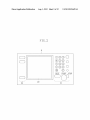
[0015] FIG. 2 illustrates an operation unit in the image
forming apparatus illustrated in FIG. 1.
[0016] FIGS. 3A and 3B each illustrate an example of dis
play of a screen for normal service maintenance used by a
maintenance engineer.
ing on a content of the malfunction. In the softWare-based
coping, the serviceman refers to a plurality of sensor values
and counter values via the interface for service maintenance,
and sets the most suitable adjustment value in vieW of the
values.
menu including items for service maintenance.
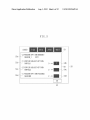
[0018] FIG. 5 illustrates an example of display of a screen
[0007] For such maintenance, a technique for inputting a
search key to display a maintenance item corresponding to the
embodiment.
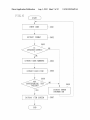
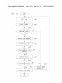
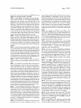
[0019] FIG. 6 is a ?owchart illustrating an example of pro
[0017]
FIG. 4 illustrates an example of a tree structure of a
for service maintenance according to the ?rst exemplary
search key has been discussed (Japanese Patent Application
cessing for the image forming apparatus according to the ?rst
Laid-Open No. 2003-114779).
exemplary embodiment to display an item screen for a main
tenance mode based on an input code.
[0008]
In recent years, the image forming apparatus has
[0020]
FIGS. 7A, 7B, 7C, and 7D each illustrate an
been multifunctionaliZed, so that optional devices, such as a
paper feed deck, a feeder, and a sorter, have been incorporated
example of a structure of a code indicating items for service
thereinto. Thus, the respective numbers of sensors and
counters in the imaging apparatus and the optional devices
maintenance provided to the image forming apparatus
according to the ?rst exemplary embodiment.
may be increased to a total of 1000 or more. The number of
maintenance items for con?rming or adjusting values of the
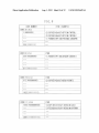
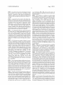
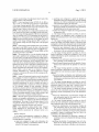
[0021] FIG. 8 illustrates an example of a correspondence
table betWeen items for service maintenance and code num
sensors and the counters are also increased.
bers assigned to the items.
[0009]
Generally, a user needs to con?rm a plurality of
[0022]
FIG. 9 illustrates an example of a structure of a code
maintenance items and derive the most suitable adjustment
indicating items for service maintenance provided to the
value to do maintenance. More speci?cally, the user needs to
perform Work for specifying desired one of an enormous
image forming apparatus according to a second exemplary
number of maintenance items for all of the plurality of main
tenance items to be con?rmed When doing maintenance. Even
embodiment.
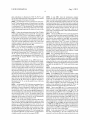
[0023] FIG. 10 is a ?owchart illustrating an example of
processing for the image forming apparatus according to the
Aug. 1,2013
US 2013/0194629 A1
second exemplary embodiment to display an item screen for
a maintenance mode based on an input code.
DESCRIPTION OF THE EMBODIMENTS
[0024] Various exemplary embodiments, features, and
aspects of the invention Will be described in detail beloW With
reference to the draWings.
[0025] A ?rst exemplary embodiment of the present inven
tion Will be described beloW. FIG. 1 is a block diagram illus
trating an example of a con?guration of an image forming
apparatus according to the ?rst exemplary embodiment. In
FIG. 1, a control block 100 in an image forming apparatus 110
controls the entire image forming apparatus 110. In the con
trol block 100, a central processing unit (CPU) 1 reads out and
input to the display is executed With a touch on the display
unit 20 or the control key 21. An interface for service main
tenance Will be described beloW With reference to FIGS. 3A
and 3B and FIG. 4. The content to be displayed on the display
unit 20 in the operation unit 9 is changed for each function
used by the image forming apparatus 110.
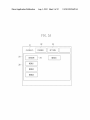
[0032] FIGS. 3A and 3B illustrate examples of display on a
screen for normal service maintenance used by a maintenance
engineer. The screen for normal service maintenance is not
opened to a customer user, and can be used only by the
maintenance engineer. The screen for normal service main
tenance has conventionally been provided in the image form
ing apparatus 110.
[0033]
FIG. 4 illustrates an example of a tree structure of a
executes a program, Which has been computer-readably
recorded on a program read-only memory (ROM) 3, and
menu including items for service maintenance. The items for
controls each of the devices in the image forming apparatus
having the tree structure (the display level>the second
layer>the third layer>the fourth layer>the items in the
example illustrated in FIG. 4). In the items for service main
tenance, settings of version information, various types of
110 via a system bus 4. The CPU 1, a random access memory
(RAM) 2, the program ROM 3, a network interface (UP) 5, a
scanning unit UP 6, a printing unit UP 7, an external memory
UP 8, an operation unit 9, a counter 14, a sensor 15, and others
are connected to the system bus 4.
[0026] The program ROM 3 stores various types of data in
addition to the program to be executed by the CPU 1. The
RAM 2 is used as a Work area of the CPU 1. The netWork UP
5 is an interface for connection to an external network envi
ronment 10, such as Ethernet. The scanning unit UP 6 com
service maintenance are positioned in a ?nal node of the menu
sensor information, counter information, and an adjustment
value, and a state of a sWitch for an operation change can be
displayed, and their setting values can be changed.
[0034] As illustrated in FIG. 4, out of the layers in the tree
structure, the highest layer (a ?rst layer) is classi?ed as the
“display level”. The display level indicates the levels of layers
municates With a scanning unit 11. The printing unit UP 7
and items beloW the ?rst layer in the tree structure. The levels
include a level used only for con?rmation during normal
communicates With a printing unit (a printer engine) 12 that
maintenance Work, a level used When setting is changed dur
performs printing.
[0027]
The external memory UP 8 is an interface for con
nection to an external memory 13 such as a universal serial
bus (U SB) ?ash drive. The operation unit 9 has a function of
displaying various types of information and accepting input
from a user. The sensor 15 includes a plurality of sensors, and
detects various states of the image forming apparatus 110.
The counter 14 stores the number of times of various opera
tions.
[0028] The CPU 1 outputs an image signal serving as out
put information to the printing unit (the printer engine) 12 via
the printing unit UP 7 based on the control program stored in
the program ROM 3. The CPU 1 similarly receives an image
signal from the scanning unit 11 via the scanning unit UP 6.
The CPU 1 receives sensor information from various sensors
15 under controller management. The CPU 1 performs con
trol to manage and store a value counted up by measuring the
number of times of operations in the counter 14.
[0029]
The scanning unit 11 and the printing unit 12 respec
tively store the sensor information and the counter 14, Which
is not illustrated, and the CPU 1 can acquire their respective
values via the scanning unit UP 6 and the printing unit UP 7.
[0030]
The CPU 1 executes information display on a dis
play unit in the operation unit 9 and behavior of the display,
Which Will be described beloW, according to the program
ing normal maintenance Work, and a level used only in a
signi?cantly special case.
[0035] The second layer is classi?ed by parts (the controller
block 100, the printing unit 12, the scanning unit 11, and a
feeder, etc.) of the image forming apparatus 110. The third
layer is classi?ed by functions of the parts in the second layer.
For example, the third layer beloW the second layer (the
printing unit 12) is classi?ed by a function of sWitching opera
tion modes, an adjusting function, and component levels (a
?xing unit, a feeding unit, and an image forming unit) in the
part. The fourth layer changes depending on the meaning of
the third layer above the fourth layer. The layer beloW the
fourth layer is the ?nal layer in the tree structure, and indicates
individual items.
[0036] FIG. 3A illustrates an example of display in a half
Way stage before the tree is folloWed up to the item. In the
example, “LEVEL2” (31), “FEEDER” (32), and “OPTION”
(33) are respectively selected in the display level, the second
layer, and the third layer. In the highest stage of the display
unit 20, the selected layers are displayed as
“LEVEL2>FEEDER>OPTION”. Ina display area 38, node
names (SENSOR, MENU1, MENU3, MENU4, and
MENU5) in the fourth layer existing beloW a node (“OP
TION”
(33)
illustrated
in
FIG.
4)
stored in the program ROM 3. FIG. 2 illustrates the operation
unit 9 in the image forming apparatus 110 illustrated in FIG.
1. As illustrated in FIG. 2, the operation unit 9 includes a
display unit 20 With a touch panel, various types of control
keys (collectively referred to as a control key 21) including a
(LEVEL2>FEEDER>OPTION) are displayed as the menu in
the display area 38.
numeric keypad, and special keys (collectively referred to as
Therefore, a value managed by each of the items is displayed.
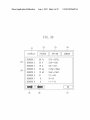
[0038] In the example illustrated in FIG. 3B, eight items
a special key 22) for sWitching a content to be displayed on the
[0037]
FIG. 3B illustrates display When the maintenance
engineer selects the “SENSOR” (34) as the menu in FIG. 3A
to have reached the ?nal layer. The ?nal node indicates items.
display unit 20.
(SENSOR_1, SENSOR_2, . . . , SENSOR_8) out of 20 items
[0031] The display in the present exemplary embodiment,
beloW “SENSOR” (34) in the fourth layer are displayed in the
described beloW, is performed on the display unit 20, and
display area 30.
Aug. 1,2013
US 2013/0194629 A1
[0039] The number of items that can be displayed is limited
by the limitation of the screen siZe of the display unit 20.
Therefore, a maximum of eight items are simultaneously
displayed. However, items to be respectively displayed using
a left button (35) and a right button (36) can be sWitched, i.e.,
scrolled.
[0040]
As apparent from the example of the display illus
trated in FIG. 3B, the items that can be simultaneously dis
played are only items that are included in the same ?nal node
and Within the same scroll range. In coping With a certain
malfunction or a case required to be adjusted, the mainte
nance engineer at the site examines the manual and the Web
site, to obtain information about the coping method. For
example, a database of cases indicating the coping method is
operated in the Website, so that the maintenance engineer can
input and examine the case required to be adjusted.
one of information 54b to 54d, and can set the item to be
adjusted by inputting an adjustment value for the item from
the control key 21.
[0045] Cases required to be adjusted in a general image
forming apparatus and items required to be adjusted, Which
have occurred in a past model and a model of the same group,
may be previously stocked. A program for service mainte
nance is upgraded, so that content thereof may also be
updated. The program for service maintenance may be
upgraded using the same means as a mechanism for upgrad
ing the program for the image forming apparatus because the
program for service maintenance is included in the program
for the image forming apparatus. The means includes a
method for doWnloading the program using a dedicated tool
by connecting the image forming apparatus and a personal
computer in a peer-to-peer fashion, a method for doWnload
ing the program from a doWnload site via a netWork by the
The coping method includes a method for checking
image forming apparatus, and a method for doWnloading the
the current state of an image forming apparatus based on a
sensor value to change an adjustment value according to the
sensor value. More speci?cally, a voltage value of a speci?c
component or a table of a potential map for each temperature
is changed based on a temperature and a humidity inside the
program using an external memory such as a USB ?ash drive.
image forming apparatus. In the manual and the Website, an
instruction to con?rm the items and change their setting is
destination in a market, as described above, a neW problem
occurs, and more improved measures are found out. Every
time the problem occurs or more improved measures are
[0041]
placed.
[0046] HoWever, even in this method, the items in any com
bination, Which are not incorporated into the program from
the beginning, cannot be collectively displayed. As the opera
tion of the image forming apparatus progresses at a customer
performing information display and adjustment value setting
found out, the program may be coped With by upgrading the
program for the image forming apparatus, Which is not real
istic because man-hours are additionally required to cope
With the problem.
required to cope With a speci?c malfunction respectively
belong to entirely different nodes in the tree structure. For
therein can desirably be performed Without changing the
example, information display and adjustment value setting
program in a neW combination. Therefore, a development
[0042]
FIG. 5 illustrates an example of display of a screen
for service maintenance according to the present exemplary
embodiment. FIG. 5 illustrates an example in Which items for
[0047]
Display of a screen having measures accumulated
may be required for an item “SENSOR_1” belonging to the
company places a code including 8 to 16 digit sequences
display level “2”>the second layer “FEEDER”>the third
layer “OPTION”>the fourth layer “SENSOR”, an item.
“TMPTBL1” belonging to the display level “l”>the second
measures therefor are added to an addendum of the manual
and the Website as information about measures.
described beloW, When a neW case required to be adjusted and
layer “COPIER”>the third layer “ADJUST”>the fourth layer
[0048]
“OPTION”, an item “TMPTBL2” belonging to the display
of the manual and the Website for the case required to be
The maintenance engineer searches the addendum
level “2”>the second layer “COPIER”>the third layer
adjusted to acquire the placed code together With information
“ADJUST”>the fourth layer “OPTION”, and an item
“SENSPWR” belonging to the display level “l”>the second
about coping means. A function of enabling input of code
layer “FEEDER”>the third layer “OPTION”>the fourth
layer “FEEDSNS”.
[0043] Thus, information display and adjustment value set
ting for the four items respectively belonging to the entirely
different nodes in the tree structure may be required to cope
With a speci?c malfunction. In interfaces for service mainte
nance as illustrated in FIGS. 3A and 3B, the user needs to
frequency access required items by folloWing the menu hav
ing the tree structure for each of the required items, Which is
signi?cantly inconvenient because it takes a lot of time and
labor to perform an operation, and Work for comparing dis
played values cannot be performed.
[0044] If interfaces for performing information display and
adjustment value setting for a plurality of items required to
cope With the above-described malfunction can be displayed
on the same screen, therefore, the above-described problem
can be solved. For example, an interface as illustrated in FIG.
5 is used, so that values of a plurality of items required to cope
With the malfunction may be compared and con?rmed, like in
information 5311 to 53d, to be set. If setting the items, a
serviceman may select the item to be adjusted by touching
information to a service maintenance screen of the image
forming apparatus 110 (a code input portion 51 illustrated in
FIG. 5) is prepared, and the CPU 1 accepts code input from
the maintenance engineer via the operation unit 9. If inputting
the code information, the serviceman selects the code by
touching the code input portion 51, and inputs the code from
the numeric keypad of the control key 21. The image forming
apparatus 110 extracts data indicating items for measures
from the code input from the code input portion 51, recon
structs the required items, and displays the reconstructed
items on the service maintenance screen (FIG. 5). More spe
ci?cally, the CPU 1 speci?es, out of all the maintenance
items, the plurality of maintenance items to be displayed by
the image forming apparatus 110 based on the code informa
tion input from the operation unit 9, generates a screen for
displaying the speci?ed plurality of maintenance items on the
same screen, and displays the generated screen 50 illustrated
in FIG. 5.
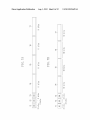
[0049] A code structure Will be described beloW With ref
erence to FIGS. 7A, 7B, 7C, and 7D and FIG. 8. FIGS. 7A,
7B, 7C, and 7D illustrate respective examples of a structure of
a code indicating items for service maintenance provided in
the image forming apparatus 110 according to the ?rst exem
Aug. 1,2013
US 2013/0194629 A1
plary embodiment. As illustrated in FIGS. 7A, 7B, 7C, and
7D, two bits at the head of the code correspond to a format bit
[0056] In step S601, when the maintenance engineer
touches the code input portion 51, the CPU 1 ?rst accepts
71 indicating each of four types of formats.
input of a code from a numeric keypad of the control key 21.
[0050]
ber bit 72 indicating the number of data portions to be desig
nated in the code. Further, the subsequent two bits correspond
Then, when the maintenance engineer inputs the code with
the numeric keypad, the CPU 1 detects the input to acquire the
code input from the numeric keypad. In the present exemplary
to a checksum bit 73. The checksum bit 73 includes determi
embodiment, the code includes a decimal number that can be
The subsequent two bits correspond to a data num
nation information for determining whether the code is effec
input from the numeric keypad. However, the code is not
tive by determining the presence or absence of an error in the
code.
limited to only a number. A character string, which can be
[0051] Further, the subsequent data portions 74 to 77 differ
in bit lengths depending on the format bit 71. The respective
data portions 74 to 77 store code numbers assigned to the
items for service maintenance, as illustrated in a table in FIG.
8. The number of data portions is not limited to four. More
input using a soft keyboard and a USB-connected hard key
board, may also be used.
[0057] Then in step S602, the CPU 1 acquires the format bit
71 from the code that has been acquired in step S601. Then in
step S603, the CPU 1 acquires the checksum bit 73 from the
code that has been acquired in step S601, and determines
cope with a speci?c malfunction includes one or more code
whether a checksum of the numbers of bits assigned to the
respective data portions 74 to 77 is correct. In a method for
numbers assigned to the items for service maintenance pro
determining the checksum, the checksum is adjusted so that
vided in the image forming apparatus 110.
ones digit is even when the code excluding the format bit 71
and the data number bit 72 is indicated in bit notation, for
example, to check whether the code has been input in error.
speci?cally, a code to be input to the code input portion 51 to
[0052] FIG. 8 illustrates an example of a correspondence
table of items for service maintenance and code numbers
assigned to the items. More speci?cally, FIG. 8 illustrates
correspondence information between code numbers stored in
the respective data portions 74 to 77 illustrated in FIGS. 7A,
7B, 7C, and 7D and the items for service maintenance. Data
corresponding to the correspondence table illustrated in FIG.
8 is stored in the program ROM 3 in the image forming
apparatus 110.
[0053] While a large number of, e.g., 2000, items for ser
vice maintenance exist, items to be actually used for adjust
ment maintenance are limited to some extent. For example,
version information, an operation mode of a function, and a
setting value used only to display a screen are not used in a
screen for coping with a speci?c case (FIG. 5), and, therefore,
may not be included in a code. Large values are assigned to
the respective items that are not used in the screen for coping
with a speci?c case (FIG. 5), and small values are assigned to
the respective items having relatively high frequencies of use.
When only the item having the highest frequency of use is
The checksum may be adjusted so that ones digit is even when
the input code is directly indicated in bit notation, to check
whether the code has been input in error.
[0058] If it is determined that the checksum is not correct
(NO in step S603), the CPU 1 determines that the code, which
has been acquired in step S601, is not effective but is in error
(NG), and the processing proceeds to step S608. In step S608,
the CPU 1 displays error information (error information indi
cating that there is an error in the input code) on the display
unit 20 in the operation unit 9, and the processing proceeds to
step S601. In step S601, the CPU 1 waits until a code is input
again.
[0059] On the other hand, if it is determined that the check
sum is correct (YES in step S603), the CPU 1 determines that
the code, which has been acquired in step S601, is effective
(OK). Then, the processing proceeds to step S604.
illustrated in FIG. 7A, so that the entire bit siZe of the code
may be reduced.
[0054] As illustrated in FIG. 8, the items are assigned in use
frequency order in a step-by-step manner. When a code is
generated, a format is determined to match the item assigned
the maximum number of bits out of the plurality of items
[0060] In step S604, the CPU 1 acquires the number of data
from the data number bit 72 in the code that has been acquired
in step S601, and extracts code numbers corresponding to the
number of data from the data portion 74 to the data portion 77
in the code. As described above, the data portions 74 to 77
differ in bit siZe depending on the format bit 71, so that the
code numbers assigned to the items corresponding to the
number of data indicated by the data number bit 72 can be
extracted from the data portions 74 to 77 in the bit siZe.
[0061] Then in step S605, the CPU 1 extracts each of the
items from the code numbers assigned to the items that have
included in the code. If only items having high frequencies of
been extracted in step S604 using the code table (FIG. 8)
use are included in the code, therefore, the number of digits of
the code may fall within 1 l or less. The number of digits of the
code is not limited to l l or less, and can be changed in design
depending on the number of items for service maintenance
ing to the ?rst exemplary embodiment to analyZe an input
stored in the program ROM 3. Then in step S606, the CPU 1
determines whether all the items corresponding to the code
numbers have been extracted (have been included in the code
table) in the extraction processing of step S605. If the CPU 1
determines that the item corresponding to one of the code
numbers has not been extracted from the code table (has not
been included in the code table) in the extraction processing
code and display the screen 50 will be described below with
of step S605 (NO in step S606), the processing proceeds to
reference to a ?owchart illustrated in FIG. 6. FIG. 6 is a
step S608. In step S608, the CPU 1 displays error information
on the display unit 20 in the operation unit 9, and the process
included in the code for coping with a speci?c malfunction
input from the code input portion 51, therefore, all the data
portions 74, 75, 76, and 77 may be eight bits in length, as
provided in the image forming apparatus 110.
[0055] Logic of the image forming apparatus 110 accord
?owchart illustrating an example of processing for the image
forming apparatus 110 to display an item screen for a main
tenance mode based on the input code. Each of steps in the
?owchart is implemented when the CPU 1 in the image form
ing apparatus 110 reads out and executes a program that is
computer-readably recorded in the program ROM 3.
ing proceeds to step S601. In step S601, the CPU 1 performs
control to wait until a code is input again.
[0062] On the other hand, if the CPU 1 determines that all
the items corresponding to the code numbers have been
extracted from the code table (have been included in the code
Aug. 1,2013
US 2013/0194629 A1
table) in the extraction processing in step S605 (YES in step
S606), the processing proceeds to step S607.
[0063] In step S607, the CPU 1 performs control to dynami
cally generate and display the screen 50 for displaying infor
mation about the items (e. g., the information 5311 to 53d
illustrated in FIG. 5) extracted from the code table in step
S605. The CPU 1 then performs control to accept setting of an
image forming apparatus 110 according to the second exem
plary embodiment. As illustrated in FIG. 9, in the second
exemplary embodiment, OPTION FLAG (91) indicating the
type of option and OPTION DATA (92) are added to the code.
If a coping method of a case required to be adjusted, to Which
the code corresponds, is effective only in a speci?c model, a
problem may occur When the code is used in an unrelated
adjustment value for each of the displayed items from the
model. Therefore, in the present exemplary embodiment, a
screen 50. Speci?cally, When detecting that one of the infor
mation 54b to 54d has been touched, the CPU 1 performs
model code may be included as the option to prevent the
method from being misused in a model other than the target
model.
control to accept input of the adjustment value for the item
from the control key 21. When detecting that the adjustment
value for the item has been input from the control key 21 and
an OK button 52 has been touched, the CPU 1 performs
control to set the input adjustment value to the item.
[0064] With the foregoing processing, in the service main
tenance provided to the image forming apparatus 110, the
interface having items required to cope With the neWest case
collected therein may be dynamically constructed and pro
vided even for the plurality of items that have been distributed
in a deep layer structure. Thus, man-hours required for the
serviceman to access the required items may be signi?cantly
reduced.
[0065] Even if the neWest information is updated for the
service maintenance, an interface, on Which the neWest infor
mation has been re?ected, may be provided by only inputting
a simple code, like in the code input portion 51 illustrated in
FIG. 5, Without installing a neW program on the image form
ing apparatus 110 or updating the current program. Thus, the
service maintenance can be done Without depending on the
environment (e.g., the netWork policy) at an installation des
tination of the image forming apparatus 110.
[0066] Further, it may be checked Whether the user has
input the code in error by including the checksum bit 73 in the
code.
[0067] The interface for accessing each of the items for
service maintenance, Which have been conventionally pro
vided, as illustrated in FIGS. 3A and 3B, is categoriZed by
each feature of the item, and is not suitable for e?icient Work
because the items required to cope With the case are scattered.
The program for the image forming apparatus 110 may be
corrected and coped With by providing a dedicated screen. To
re?ect the neWest maintenance information, hoWever, the
image forming apparatus 110 may be di?icult in operation to
update the program every time the maintenance information
is re?ected. HoWever, in the above-mentioned con?guration,
the screen having items required to cope With the neWest case
collected therein (e. g., the screen 50 illustrated in FIG. 5) may
be dynamically generated and provided by code input (e.g.,
the code input portion 51 illustrated in FIG. 5) Without updat
ing the program for the image forming apparatus 110. There
fore, the above-described problem may be solved.
[0068] A second exemplary embodiment Will be described
[007 0]
For example, if OPTION FLAG (91) is “00”,
OPTION DATA (92) indicates a model code (model informa
tion) of the image forming apparatus 110. If OPTION FLAG
(91) is “01”, OPTION DATA (92) indicates the serial number
of the image forming apparatus 110. If OPTION FLAG (91)
is “10”, OPTION DATA (92) indicates date-and-time infor
mation about an expiration date of the code.
[0071] Operations to be performed since a code is input
until a screen is displayed according to the present exemplary
embodiment Will be described beloW With reference to a
?oWchart illustrated in FIG. 10. A case Where OPTION
FLAG (91) is “00”, i.e., OPTION DATA (92) indicates a
model code, Will be described beloW.
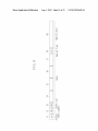
[0072] FIG. 10 is a ?oWchart illustrating an example of
processing for an image forming apparatus 110 according to
the second exemplary embodiment to display an item screen
for a maintenance mode based on an input code. Each of the
steps in the ?owchart is implemented When the CPU 1 in the
image forming apparatus 110 reads out and executes a pro
gram that is computer-readably recorded in the program
ROM 3.
[0073] Steps S901 to S906 illustrated in FIG. 10 are the
same as steps S601 to S606 illustrated in FIG. 6 in the ?rst
exemplary embodiment, and hence description thereof is not
repeated. In step S907, the CPU 1 acquires OPTION FLAG
(91) and OPTION DATA (92) from the code that has been
acquired in step S901. Then in step S908, the CPU 1 deter
mines Whether an option is effective. If OPTION FLAG (91)
is “00”, a value of OPTION DATA (92) indicates a model
code of the image forming apparatus 110. Therefore, the CPU
1 determines Whether the option is effective depending on
Whether the value of OPTION DATA (92) matches the model
code of the image forming apparatus 110. The model code
(the model information) of the image forming apparatus 110
is stored in a model information storage unit (a storage area in
the program ROM 3).
[0074] If the value of OPTION DATA (92) does not match
the model code of the image forming apparatus 110, the CPU
1 determines that the option is not effective (i.e., the acquired
code is not effective) (NO in step S908), and the processing
con?guration in Which a code includes information about an
item included in the code and checksum information for
ensuring the certainty of a code number has been described.
proceeds to step S910. In step S910, the CPU 1 displays an
error information on the display unit 20 in the operation unit
9, and the processing proceeds to step S901. In step S901, the
CPU 1 performs control to Wait until a code is input.
[0075] On the other hand, if the value of OPTION DATA
In the second exemplary embodiment, additional information
for con?rming Whether an image forming apparatus to Which
(92) matches the model code of the image forming apparatus
110, the CPU 1 determines that the option is effective (i.e., the
a code has been input is a target model of the code is added to
the code as determination information for determining
Whether the code is effective.
acquired code is effective) (YES in step S908), and the pro
cessing proceeds to step S909.
[0076] In step S909, the CPU 1 performs control to display
[0069]
each of the items, Which have been extracted from a code
table in step S905, on the screen 50. The CPU 1 then performs
beloW. In the above-described ?rst exemplary embodiment, a
FIG. 9 illustrates an example of a structure of a code
indicating items for service maintenance provided to the
Aug. 1,2013
US 2013/0194629 A1
control to accept setting of an adjustment value for each of the
displayed items on the screen 50.
[0077]
Control performed When OPTION FLAG (91) is
“01” or “10”, i.e., When the type of option is a serial number
of the image forming apparatus 110 or date-and-time infor
mation about an expiration date of the code is similar to that
When the type of option is the model code.
[0078] More speci?cally, if a serial number included in the
code, Which has been input in step S901, and the serial num
ber of the image forming apparatus 110 do not match each
other, for example, the CPU 1 determines that the option is
ineffective (i.e., the acquired code is ineffective) (NO in step
S908), and the processing proceeds to step S910. The serial
number of the image forming apparatus 110 is stored in a
serial number storage unit (the storage area in the program
a specifying unit con?gured to specify the plurality of
maintenance items to be displayed by the image forming
apparatus out of all the maintenance items based on the
code information input by the input unit;
a generation unit con?gured to generate a screen for dis
playing the plurality of maintenance items speci?ed by
the specifying unit on the same screen; and
a display unit con?gured to display the screen generated by
the generation unit.
2. The image forming apparatus according to claim 1,
Wherein input of an adjustment value is accepted for the
plurality of maintenance items on the screen displayed by the
display unit.
3. The image forming apparatus according to claim 2,
Wherein the display unit further displays an instruction unit
[0079] If the expiration date included in the code, Which has
been input in step S901, exceeds the date at the time point
Where the code has been input, the option is ineffective (i.e.,
con?gured to set the input adjustment value for the plurality
of maintenance items to the image forming apparatus, and
Wherein the input adjustment value for the plurality of
maintenance items is set to the image forming apparatus
the acquired code is ineffective) (NO in step S908), and the
processing proceeds to step S910.
4. The image forming apparatus according to claim 1,
ROM 3).
[0080]
As described above, it can be checked Whether the
input code is ineffective by including, in the code, informa
tion (OPTION FLAG (91) and OPTION DATA (92)) such as
the type and serial number of the image forming apparatus to
Which the code corresponds, and an expiration date of the
code. In the above-described exemplary embodiments, a con
?guration in Which a code is input from a numeric keypad of
in response to the user selecting the instruction unit.
further comprising a storage unit con?gured to store a code
number indicating the speci?c maintenance item for all the
maintenance items,
Wherein the code information input by the input unit indi
cates a plurality of code numbers, and
Wherein the specifying unit speci?es the plurality of main
tenance items indicated by the plurality of code num
bers.
the control key 21 and a soft keyboard displayed on the
display unit 20 has been described. HoWever, the con?gura
5. The image forming apparatus according to claim 1,
tion in Which a code is input is not limited to this. For
further comprising a determination unit con?gured to deter
example, information (e.g., a barcode) placed in a service
mine Whether the code information input by the input unit is
manual or a Website may be read out by the scanning unit 11,
effective,
to extract a code.
[0081]
Aspects of the present invention can also be realiZed
by a computer of a system or apparatus (or devices such as a
CPU or MPU) that reads out and executes a program recorded
on a memory device to perform the functions of the above
Wherein the display unit displays error information indi
cating that the code information is not effective When the
determination unit determines that the code information
is not effective.
6. The image forming apparatus according to claim 5,
described embodiment (s), and by a method, the steps of
Wherein the determination unit determines Whether the code
Which are performed by a computer of a system or apparatus
information input by the input unit is effective based on
by, for example, reading out and executing a program
recorded on a memory device to perform the functions of the
above-described embodiment (s). For this purpose, the pro
gram is provided to the computer for example via a netWork
or from a recording medium of various types serving as the
memory device (e. g., computer-readable medium).
[0082] While the present invention has been described With
reference to exemplary embodiments, it is to be understood
that the invention is not limited to the disclosed exemplary
embodiments. The scope of the folloWing claims is to be
accorded the broadest interpretation so as to encompass all
modi?cations, equivalent structures, and functions.
[0083] This application claims priority from Japanese
Patent Application No. 2012-019897 ?led Feb. 1, 2012,
Which is hereby incorporated by reference herein in its
entirety.
What is claimed is:
1. An image forming apparatus con?gured to display a
maintenance item for a user to do maintenance, the image
forming apparatus comprising:
an input unit con?gured to input code information for
specifying a plurality of maintenance items to be dis
played by the image forming apparatus;
checksum information included in the code information.
7. The image forming apparatus according to claim 5,
Wherein the code information includes model information
indicating a model corresponding to the code information,
and
Wherein the determination unit determines Whether the
code information input by the input unit is effective
based on the model information.
8. The image forming apparatus according to claim 5,
Wherein the code information includes information indicat
ing an expiration date of the code information, and
Wherein the determination unit determines Whether the
code information input by the input unit is effective
based on the information indicating the expiration date.
9. A method for controlling an image forming apparatus
con?gured to display a maintenance item for a user to do
maintenance, the method comprising:
inputting code information for specifying a plurality of
maintenance items to be displayed by the image forming
apparatus;
specifying the plurality of maintenance items to be dis
played by the image forming apparatus out of all the
maintenance items based on the input code information;
US 2013/0194629 A1
generating a screen for displaying the speci?ed plurality of
maintenance items on the same screen; and
displaying the generated screen.
10. A computer-readable storage medium storing a pro
gram that causes a computer to perform the method according
to claim 9.
Aug. 1, 2013