1
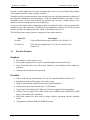
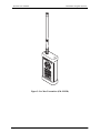
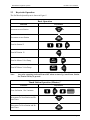
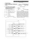
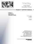
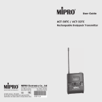
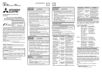
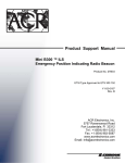
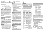
FM Remote Control System
Pro Max
User Manual
Models:
PROMAX
PROMAX-UA
Document No. 500055 Rev. E
Rain Master Irrigation Systems
Pro Max User’s Manual
Table of Contents
1.0 Introduction........................................................................................................1
1.1
1.2
1.3
Pro Max Features................................................................................................................ 2
Ranges and Method of Transmission ................................................................................. 3
Licensing Information ........................................................................................................ 4
2.0 Model Pro Max Remote Control System (Rain Master Only) ......................6
2.1 Using the Receiver with a Rain Master Controller ............................................................ 7
2.1.1 Connecting the Receiver to a Rain Master Controller .................................................. 7
2.1.2 Disconnecting the Receiver from a Rain Master Controller......................................... 8
2.2 Permanent Mount Pro Max Receiver ................................................................................. 8
2.3 Keystroke Operation......................................................................................................... 11
2.3.1 Evolution DX2 Keystroke Operations ........................................................................ 14
3.0 Model Pro Max-UA Remote Control System (Universal) ...........................15
3.1
3.2
3.3
3.4
3.5
3.6
3.7
3.8
3.9
Using the Pro Max-UA Universal Adapter with a Non Rain Master Controller ............. 16
Installing the Pro Max-UA System .................................................................................. 16
Temporary Connector Installation.................................................................................... 19
Disconnecting the Pro Max-UA from a Non-Rain Master Controller ............................. 19
Non-Rain Master Controllers Lacking 24 Volts AC........................................................ 19
Disconnecting the Pro Max-UA from a Non-Rain Master Controller ............................. 20
Non-Rain Master Controllers Lacking 24 Volts AC........................................................ 20
Permanent Wire Connections ........................................................................................... 20
Keystroke Operation......................................................................................................... 21
4.0 Detailed Operation...........................................................................................22
4.1 Remote Operation............................................................................................................. 22
4.2 Stations On and Off .......................................................................................................... 22
4.3 Auto Up and Auto down Keys ......................................................................................... 23
4.4 On and Off Keys............................................................................................................... 23
4.5 Master Valve/Pump Key .................................................................................................. 23
4.6 Controller Access Code.................................................................................................... 24
4.7 Add Stations ..................................................................................................................... 25
4.7.1 Add Stations – On Key ............................................................................................... 25
4.7.2 Add Stations – Auto Up and Auto down Keys ........................................................... 25
4.7.3 Add Stations - Off Key ............................................................................................... 25
4.8 Program Function ............................................................................................................. 26
4.8.1 Program – Off Key...................................................................................................... 26
4.8.2 Program – Auto up Key .............................................................................................. 26
4.8.3 Program - Sensor Switches ......................................................................................... 26
4.9 Minutes Function.............................................................................................................. 27
4.10 Beeper Operation.............................................................................................................. 27
4.10.1 Power on Beeper Operation ....................................................................................... 27
4.10.2 Universal Adapter Over-Current Detection Beeper................................................... 28
4.11 Transmitter Battery Replacement..................................................................................... 28
Page i
Pro Max User’s Manual
Rain Master Irrigation Systems
5.0 Checking Out Electrical Problems.................................................................30
5.1
5.2
5.3
Field Wiring Shorts, the Receiver, and Rain Master Controllers..................................... 30
Field Wiring Shorts, the Receiver, and Non Rain Master Controllers............................. 30
A Note about Solenoids.................................................................................................... 30
6.0 Troubleshooting ...............................................................................................31
7.0 Pro Max Specifications....................................................................................33
7.1
7.2
7.3
7.4
Pro Max Transmitter ........................................................................................................ 33
Pro Max Receiver ............................................................................................................. 33
Pro Max Universal Adapter.............................................................................................. 33
Pro Max Carrying Case .................................................................................................... 33
8.0 Pro Max Series Parts List ...............................................................................34
Rain Master Limited Warranty ...........................................................................35
Page ii
Rain Master Irrigation Systems
Pro Max User’s Manual
Table of Figures
Figure 1: Pro Max FM Remote Control System............................................................................ 1
Figure 2: Complete Pro Max System.............................................................................................. 6
Figure 3: Pro Max Receiver to Rain Master Controller.................................................................. 8
Figure 4: Permanent Mount Pro Max Receiver .............................................................................. 9
Figure 5: Pro Max Transmitter (PM-XMTR) ............................................................................... 10
Figure 6: Complete Pro Max-UA System..................................................................................... 15
Figure 7: Relay (such as Rain Master RLY1)............................................................................... 17
Figure 8: Pro Max-UA Installation to a Non-Rain Master Controller.......................................... 19
Figure 9: Non-Rain Master Controller 24 Volts AC .................................................................... 20
Figure 10: Pro Max-UA Permanent Connection .......................................................................... 21
Figure 11: Battery Replacement ................................................................................................... 28
Notice:
Information furnished by Rain Master Irrigation Systems Inc. is believed to be accurate and
reliable. However, Rain Master shall not be liable for errors contained herein or for incidental
or consequential damages in connection with the furnishing, performance or use of this
material.
The information contained in this document is subject to change without notice.
Page iii
Rain Master Irrigation Systems
Pro Max User’s Manual
Pro Max
Congratulations… you have chosen one of the ultimate weapons to use in keeping maintenance
costs down and satisfaction high – the Rain Master Pro Max Remote Control System. Rain
Master engineer’s take great pride in all their work, but they are especially proud of Pro Max.
You’ll find it packed with features you’ve been looking for and it’s extremely easy for everyone
to use. Pro Max has been designed to give you years of dependable service.
To take full advantage of all the ways Pro Max can help you do your job more efficiently and
economically, please take a few minutes and read your User Manual. It won’t be long before
your best friend in the field is Pro Max.
Figure 1: Pro Max FM Remote Control System
1.0 Introduction
The Pro Max Remote Control System is designed to save valuable time and energy, which would
have been spent walking back and forth between the controller and the irrigation field zone
Page 1
Pro Max User’s Manual
Rain Master Irrigation Systems
location. It makes light work of system checkouts and service work, providing field personnel
with complete control over the irrigation controller.
Controllers may be operated remotely from watering zone sites allowing immediate evaluation of
the irrigation configuration and performance. Using the hand-held battery operated Pro Max
Transmitter from a remote zone location; the operator may turn ON a single station or any
number of stations with the push of a few simple keys.
An access code feature allows independent control of multiple Pro Max receivers permanently
installed in up to 999 controllers. In addition to the maintenance features, the Pro Max system
provides specialized irrigation functions, which are described in Section 1.1.
The Pro Max remote control system is composed of two model numbers:
1.1
Model No.
Pro Max
Description
Used with Rain Master only controllers. (See Section 2.0)
Pro Max-UA
Used with any manufacturers’ 24-volt AC controller. (See
Section 3.0)
Pro Max Features
Simplicity
•
•
•
•
The industries easiest remote to use.
Fits in shirt or pants pocket or can be attached using the convenient belt clip.
Large dedicated feature keys allow most functions to be performed with a single key
operation.
Auto-up and auto-down station operation.
Flexibility
•
•
•
•
•
•
•
•
Page 2
Can be used with any manufacturers’ 24-volt AC controller (Model Pro Max-UA).
Independent control of the master valve and/or pump.
Single or multi-station capabilities for testing system hydraulics.
Timed station operation selectable from 1 to 60 minutes.
Control up to 999 individual Pro Max receivers from a single Pro Max transmitter.
Ability to turn a program ON or OFF (when used with RME Sentar, RME Hawk, RME
Eagle, or Evolution DX2 controllers).
Small and compact Pro Max receiver design facilities permanent internal controller
mount.
Compatibility with Rain Master RT5/RRAD remote.
Rain Master Irrigation Systems
Pro Max User’s Manual
Intelligence
•
•
•
•
•
•
•
•
Detects and provides an audible alert against field wiring short circuits (Model Pro MaxUA).
No more tripped circuit breakers or blown fuses during installation checkout.
Receiver has built-in safety default to automatically turn station OFF after 60 minutes.
Audible Pro Max transmitter and Pro Max receiver tones verify proper Pro Max remote
control operations at all times.
High tech power saver circuitry means no more battery recharging required (no down
time).
Transmitter has a single replacement lithium battery that can be purchased locally and
field replaced. The battery will last an entire season, under normal conditions.
Audible low battery alert.
No fuses required.
Durability
•
•
Tough, rugged all metal construction with shock absorbing rubber bumpers.
Hard cover case for carefree transportation.
Reliability
•
1.2
Utilizes three mechanisms to insure reliable, interference-free communications.
- Digital filters
- Factory set coding
- VHF FM communications
Ranges and Method of Transmission
It is not possible to exactly predict the distance over which the Pro Max system will perform.
Several factors may affect the distance and reliability of any radio transmission:
•
•
•
•
•
Frequency used
Terrain
Building Structures
On channel interference
Antenna types
•
•
•
•
•
Transmission Power
Antenna placement
Weather conditions
Atmospheric disturbances
Mode of operation (AM, FM, etc.)
Your Pro Max system has been designed to operate at distances up to one mile. Under ideal open
field conditions, it can readily operate up to 5 miles.
When attempting to use Pro Max over extended distances, it is important to ensure that the
receiving antenna is properly located. If possible, avoid Pro Max receiver antenna locations,
Page 3
Pro Max User’s Manual
Rain Master Irrigation Systems
which are indoors, especially basements, or structures, which are concrete and steel. It may be
possible to remotely locate an external antenna whenever poor Pro Max receiver locations exist.
Call Rain Master Technical support for assistance, telephone (805) 527-4498. Moving the Pro
Max transmitter to a more favorable location or usage of optional high gain antennas on both the
Pro Max transmitter and Pro Max receiver may improve operations.
The Pro Max system utilizes VHF/FM communications and the Pro Max receiver/Pro Max
transmitter pair is factory encoded to insure that other services including other Rain Master
remotes do not interfere or false trigger the Pro Max receiver. Digital filtering further enhances
operation in interference prone environments. FM transmission is employed for its inherent
quality and immunity to atmospheric, static, and electrical interference which are commonly
found in AM types of equipment such as citizen’s band radio, garage door openers, etc. Usage of
FM transmissions also insures that the stronger signal prevails (capture ratio), meaning that all
received signals, which are weaker than the Pro Max transmission, are completely overridden.
Note:
1.3
Antennas are not just a piece of wire; they are cut for a precise frequency of
operation in order to ensure optimal performance. When using antennas with the
Pro Max system, only utilize Rain Master specified parts, which are available
through your authorized Rain Master distributor.
Licensing Information
Your Rain Master Pro Max radio operates on FM radio communication frequencies and is
subject to the rules and regulations of the local communications governing agencies. These
agencies may require that all operators using private land mobile or general mobile radio
frequencies obtain a radio license before operating their equipment. The operator receives a
license for use of the radio equipment under a specific eligibility and ON a particular frequency
or set of frequencies. To determine eligibility for use of private land mobile service frequencies,
contact your local communications governing agency. This agency can supply information
required to properly obtain and complete the license application form.
For U.S. License Applications, contact:
FCC Forms Distribution Center
1 (800) 418-3676
Request form 600 and all schedules and instructions.
For license questions call the FCC at 1 (888) 225-5322.
The following are addresses of communications agencies in North America:
Page 4
United States
Canada
Federal Communications Commission
1270 Fairfield Road
Gettysburg, PA 17325-7245
1-800-322-1117
Department of Communications
1241 Clyde Avenue
Ottawa, Ontario
K2C 143
Rain Master Irrigation Systems
Pro Max User’s Manual
Mexico
Sectretaria De Comunicaciones
Y Transportes
Direccion General de Politicas Y Normas de Comunicaciones
Av. Eugenia No. 197-5o. Piso
Mexico, D.F. 06700
Page 5
Pro Max User’s Manual
Rain Master Irrigation Systems
2.0 Model Pro Max Remote Control System (Rain Master Only)
The Pro Max receiver is designed to connect directly to any Rain Master controller by plugging
the 9-pin connector from the Pro Max receiver into the front panel remote control jack found ON
Rain Master controllers.
Figure 2: Complete Pro Max System
Pro Max Parts List
Part No.
Ref.
Description
PM-XMTR
1
Pro Max Remote radio transmitter
PM-RCVR
2
Pro Max Remote receiver
PM-SER99
3
36” remote cable
500055
4
Pro Max User’s manual
PM-CASE
5
Pro Max carrying case
PM-ANT-XMTR
6
Antenna, BNC
PM-ANT-RCVR
7
Antenna, hinged, BNC
Page 6
Rain Master Irrigation Systems
2.1
Pro Max User’s Manual
Using the Receiver with a Rain Master Controller
One of the unique and patented features of Rain Master Controllers is the built-in capability for
remote control. Making the connections between the hand held remote transmitter and the Pro
Max receiver, which is attached to the controller, takes just a few seconds.
2.1.1 Connecting the Receiver to a Rain Master Controller
Connecting the Pro Max receiver to the controller is a very simple operation. The following
procedure steps are all that is required. Please refer to Figure 3: Pro Max Receiver to Rain
Master Controller.
Step 1
Make sure the controller is in the Automatic mode press the controllers’ QUIT
key.
Step 2
Make sure the controller’s Rain Switch, if so equipped, is in the automatic
watering position.
Step 3
Place the Pro Max receiver on top of the controller with the antenna pointing
straight up. Do not allow the antenna to touch any metal objects or wire.
Step 4
Connect the female end of the PM-SER99 cable to the Pro Max receiver and
secure with lock screws. Hands tighten only. Connect the other end of the cable
to the remote control receptacle on the front panel of the controller (it is keyed
to fit only in one way).
The controller’s display will either go blank or indicate that the remote is active.
The Pro Max receiver will beep to indicate that it is ready for use.
Note:
NEVER operate the Pro Max transmitter without the
CORRECT antenna properly installed.
Page 7
Pro Max User’s Manual
Rain Master Irrigation Systems
Upon Receiver Connection
Beep Response
1 Beep (1/2 sec)
2 Beeps
3 Beeps
Description
Ready
Multi-Pro Max receiver mode:
• Requires corresponding access code to
enable Pro Max receiver operation.
Failed internal diagnostic tests. Contact Rain
Master.
Figure 3: Pro Max Receiver to Rain Master Controller
2.1.2 Disconnecting the Receiver from a Rain Master Controller
To disconnect the Pro Max Pro Max receiver, follow the procedure below.
Step 1
2.2
Disconnect the Pro Max receiver’s plug from the controller’s front panel by
grasping the plug housing, not the cable, and pulling straight out. The controller
display should now return to the automatic screen display.
Permanent Mount Pro Max Receiver
Pro Max Receivers may be permanently installed into any Rain Master controller.
Two items are required for permanent controller installation:
Page 8
Rain Master Irrigation Systems
Pro Max User’s Manual
1. Part No. JACK-IRC
•
•
Factory installed permanent interface.
Factory programmed Pro Max receiver with a programmed access code (1-999). Access
codes are required whenever one Pro Max transmitter controls multiple Pro Max Pro
Max receivers.
2. Part No. PMRKIT
• Permanently mounted Pro Max receiver
• Antenna Pro Max-ANT
• All interconnecting cables and hardware
Note:
Operation of a permanent mount Pro Max receiver requires usage of the
ACCESS CODE feature key. Refer to section 4.6.
Figure 4: Permanent Mount Pro Max Receiver
Page 9
Pro Max User’s Manual
Rain Master Irrigation Systems
Figure 5: Pro Max Transmitter (PM-XMTR)
Page 10
Rain Master Irrigation Systems
2.3
Pro Max User’s Manual
Keystroke Operation
The Pro Max keyboard layout is shown in Figure 5.
Basic Operation
Function
Keystrokes
Increment to next Station
Decrement to next Station
1
Turn On Station 12
2
Turn Off Station 12
Turn On Master Valve/Pump
MV
PUMP
Turn Off Master Valve/Pump
MV
PUMP
Note:
Any prior operating station will turn OFF when an Auto-Up, Auto-Down, Station
On, Station Off key is pressed.
Timed Station Operation (Minutes) *
Function
Turn On Station 1 for 5 minutes
Keystrokes
1
5
MINUTES
Increments To Next Station and Restart Timer
Decrement To Next Station and Restart Timer
Page 11
Pro Max User’s Manual
Rain Master Irrigation Systems
Multiple Stations On (Add Stations)
Function
Keystrokes
Turn On Multiple Stations
1, 2, 6,
1
ADD
STATIONS
2
ADD
STATIONS
6
ADD
STATIONS
6
Turn Station 6 OFF
(Station 1, 2 remain)
Turn All Stations OFF
Turn All Stations OFF
and Increment the stations
selected From Last
Station
* When this function is used with the Rain Master RME Sentar, RME Hawk, or Evolution DX2
controllers, the controller will automatically turn ON the appropriate Master Valve or Pump.
Program Operation (Program) **
Function
Turn Program 5 On
Increment to Next Station in
Program
Turn Program 5 Off
Page 12
Keystrokes
PROGRAM
5
Rain Master Irrigation Systems
Pro Max User’s Manual
Using Multiple Receivers (Access Code)
Function
Keystrokes
Enable Pro Max Receiver #15.
Controller now accepts all
remote keys.
ACCESS
CODE
1
5
Disable Pro Max Receiver #15
ACCESS
CODE
1
5
Disable All Pro Max Receivers
ACCESS
CODE
** This function only works with the following Rain Master controllers: RME Sentar, Hawk,
Eagle, Evolution DX2 controllers. Only one program can be operated at a time.
Page 13
Pro Max User’s Manual
Rain Master Irrigation Systems
2.3.1 Evolution DX2 Keystroke Operations
The following operations are only available when using the Pro Max Remote Control System
with the Rain Master Evolution DX2 Controller:
Evolution DX2 Master Valve
Function
Keystrokes
Turn On Master Valve One
MV
PUMP
1
Turn ON Master Valve Two
MV
PUMP
2
MV
PUMP
3
MV
PUMP
3
MV
PUMP
4
Turn On Normally Open Master
Valve
(Closes the normally open
valve)
Turn Off Normally Open
Master Valve
(Valve returns to normally open
state)
Turn On Pump
Page 14
Rain Master Irrigation Systems
Pro Max User’s Manual
3.0 Model Pro Max-UA Remote Control System (Universal)
The Pro Max-UA Universal Adapter Model offers the capability to connect to virtually any
controller, regardless of manufacturer. This system consists of:
Figure 6: Complete Pro Max-UA System
Pro Max-UA Parts List
Part No.
PM-XMTR
PM-RCVR
PM-SER99
PM-UADAPT
32 PC
500055
PM-CASE
PM-ANT-XMTR
PM-ANT-RCVR
Ref.
1
2
3
4
5
6
7
8
9
Description
Pro Max Remote radio transmitter
Pro Max Remote receiver
36” remote cable
Universal adapter
30” permanent connector
Pro Max User Manual
Pro Max carrying case
Antenna, BNC
Antenna, hinged, BNC
Page 15
Pro Max User’s Manual
Rain Master Irrigation Systems
The Universal Adapter is equipped with a 35-conductor connection cable RMIS Part Number
32PC, which must be physically wired to each station of the generic controller.
Note:
If you have purchased model Pro Max-UA and you need to connect to a
Rain Master controller, the Universal Adapter box (PM-UDAPT) is not
required. Refer to section 2.0 for installation and operation.
In cases where the controller does not provide the required 24 Volts AC, a step-down
transformer is employed to convert standard 117 Volts AC or 220 Volts AC to 24 Volts AC.
3.1
Using the Pro Max-UA Universal Adapter with a Non Rain Master
Controller
The controller serves only two purposes when using the Universal Adapter.
First, it provides 24 Volts AC for the Pro Max receiver. Never allow more than the “normal” 24
Volts AC (up to 28 Volts AC maximum) to enter the Pro Max receiver through the wires
designated for 24 Volts AC. If the controller runs ON a voltage other than 24 Volts AC, use a
step-down transformer to convert the voltage to 24 Volts AC for input to the Pro Max receiver.
Transformers that convert higher voltages to 24 Volts AC are available from Rain Master.
Secondly, the controller serves as a point of connection for the field wires and the Pro Max
receiver’s output. Usually the point of connection is the terminal strip or a quick disconnect
within the controller or pedestal. Rain Master offers several types of connector cables for wiring
to the controller. The RMIS Part Number 32PC or RMIS Part Number 24PC Permanent
Connector Cable, which is intended to be permanently connected to the controller. The other is
the RMIS Part Number 32TC Temporary Connector using alligator clips.
3.2
Installing the Pro Max-UA System
To install a Permanent Connector, follow the instructions below. Prior to installation, please
observe the following precautions:
CAREFUL
WARNING:
CAUTION
DANGER
STOP – PLEASE READ ALL INSTRUCTIONS AND
THE FOLLOWING WARNING MESSAGES
BEFORE OPERATING THIS EQUIPMENT.
Always use with the approved Rain Master cable connector assemblies (RMIS Part Number
24PC, RMIS Part Number 32PC, RMIS Part Number 32TC, RMIS Part Number 32EX) Use of
any other connector will void the warranty and may damage the Pro Max remote control system.
NEVER allow more than the “normal” 24 Volts AC to enter the Universal Adapter on
any of its wires. If there is any question about a connection voltage, check the voltages
with a voltmeter.
NEVER operate the Pro Max transmitter without the CORRECT antenna properly
installed.
Page 16
Rain Master Irrigation Systems
Pro Max User’s Manual
NEVER connect the Universal Adapter to more than one controller at a time.
Procedure (Refer to Figure 7)
Step 1
Remove power from the controller.
Step 2
Connect a single wire to each station (up to 32) of the RMIS Part Number 32PC
wiring harness at the controller’s terminal strip. The field wiring should remain
connected and in place. Simply add the RMIS Part Number 32PC wiring to it.
Make sure to follow the station color code-wiring list illustrated ON the back
cover of this manual.
Note:
The chart defines the connections for the following cables:
RMIS Part Number 32PC (supplied with Pro Max-UA),
RMIS Part Number 24PC, 12PC, and RMIS Part Number
32TC.
Make sure that any unused station wires on the PC cables are insulated and will
not short to any metal object.
If there is a Master Valve and/or Pump in the system, make sure you understand
how they are controlled before hooking up the Master Valve and/or Pump wire
of the Permanent Connector. If there is any doubt - find out before connecting it
to a voltage above the “normal” 24Volts AC will damage the Pro Max Pro Max
receiver unit.
If the Controller Supplies 24 Volts AC to activate the Master Valve/Pump, then
connect the Master Valve/Pump wire of the Permanent Connector to the
controller’s Master Valve/Pump terminal.
If the Controller acts as a switch to activate the Master Valve/Pump Finding two
terminals in the controller associated with the Master Valve/Pump usually, but
not always, indicates that a relay will be required. The relay is wired such that
its coil terminals are activated by the Master Valve/Pump and COMMON of the
PC and its switch contacts are in parallel with the controller’s two terminals, see
Figure 4 below.
From MV/P wire
of the Interface
Cable
To MV/P Switch
Type Terminals
of controller
Common of the
Cable or
Controller
Figure 7: Relay (such as Rain Master RLY1)
Page 17
Pro Max User’s Manual
Rain Master Irrigation Systems
Step 3
Connect the wire for the PC Cable COMMON to the COMMON terminal of the
controller.
Step 4
Important! If 24 Volts AC is not available from the controller’s terminal strip,
see Section 3.5 and skip to Step 6 below.
Step 5
Connect the wire from the PC cables 24 Volts AC to the 24 Volts AC terminal
of the controller. Note that the PC cable has only one wire for 24 Volts AC
despite the controller having two 24 Volts AC terminals. This is because the
controller takes one of its 24 Volts AC terminals and connects it to the
COMMON terminal and you have already attached the PC cables COMMON
wire to the controller’s COMMON terminal.
You must find which 24 Volts AC terminal on the controller is NOT electrically
the same as the controller’s COMMON terminal and connect the PC’s 24 Volt
AC wire to it.
Using a voltmeter, power up the controller and set the voltmeter on a 30 Volts
or higher AC scale. Place one of the voltmeter leads ON the controller’s
COMMON terminal and use the other lead of the meter to read each of the 24
Volt AC terminals. Connect the PC cables 24 Volt AC wire to whichever
terminal gives a reading of 24 Volt AC on the meter.
If the controller does not have any terminals marked 24 Volts AC then leave
one of the voltmeter leads ON the controller’s COMMON and try the other lead
of the meter to measure the low voltage wires ON the secondary of the
controller’s transformer. Connect the PC cables 24 Volts AC wire to whichever
terminal provides a reading of 24 Volts AC ON the meter.
Step 6
Place the Rain switch in the OFF or Rain position.
Step 7
Connect the 9-pin female end of the PM-SER99 cable to the Pro Max receiver
and the male end to the universal adapter. Hands tighten the screw locks.
Step 8
Align the large connector of the RMIS Part Number 32PC cable with the
connector ON the universal adapter and plug them together.
Step 9
Reconnect power to the controller. Refer to the following table:
Upon Receiver Connection
Beep Response
1 Beep (1/2 sec)
2 Beeps
3 Beeps
No Beeps
Page 18
Description
Ready for use.
Multi-Pro Max receiver mode:
• Requires corresponding access code to enable Pro
Max receiver operation.
Failed internal diagnostic tests. Contact Rain Master.
Check the 24 Volts AC and COMMON connections.
Rain Master Irrigation Systems
3.3
Pro Max User’s Manual
Temporary Connector Installation
The RMIS Part Number 32TC Temporary Cable is wired in the exact same fashion as the
Permanent Cable Connector described above except that it uses alligator clips for connection to
the terminal strip within the controller so that it may be easily installed and removed. Follow the
connection instructions for the permanent connector; be very careful that the alligator clips are
secure and not “shorting” to any metal or each other.
3.4
Disconnecting the Pro Max-UA from a Non-Rain Master Controller
To disconnect the universal adaptor, use the following procedure:
Step 1
3.5
Disconnect the large 37 pin connector plug from the universal adaptor by
grasping the plug’s body, not by the cable, and pull straight out.
Non-Rain Master Controllers Lacking 24 Volts AC
24 Volts AC is required to power the Universal Adapter. If 24 Volts AC is not available from the
controller, use a step-down transformer to convert from the line voltage (usually 117 or 240
Volts AC) to 24 Volts AC and run the 24 Volts AC wire into the PC cable to the two wires
designated for 24 Volts AC and COMMON. There is no need to worry about the polarity of
these two connections. Additionally, connect the PC cables COMMON wire to the controller’s
COMMON terminal. Do not connect the PC cables 24 Volts AC wire to the controller.
Figure 8: Pro Max-UA Installation to a Non-Rain Master Controller
Page 19
Pro Max User’s Manual
3.6
Rain Master Irrigation Systems
Disconnecting the Pro Max-UA from a Non-Rain Master Controller
To disconnect the universal adaptor, use the following procedure:
Step 1
3.7
Disconnect the large 37 pin connector plug from the universal adaptor by
grasping the plug’s body, not by the cable, and pull straight out.
Non-Rain Master Controllers Lacking 24 Volts AC
24 Volts AC is required to power the Universal Adapter. If 24 Volts AC is not available from the
controller, use a step-down transformer to convert from the line voltage (usually 117 or 240
Volts AC) to 24 Volts AC and run the 24 Volts AC wire into the PC cable to the two wires
designated for 24 Volts AC and COMMON. There is no need to worry about the polarity of
these two connections. Additionally, connect the PC cables COMMON wire to the controller’s
COMMON terminal. Do not connect the PC cables 24 Volts AC wire to the controller.
Non-Rain Master Controller
without 24 VAC
COMMON
Transformer
High Voltage
Input
COMMON on PC
24 VAC
Output of
Transformer
24 VAC on PC
Figure 9: Non-Rain Master Controller 24 Volts AC
3.8
Permanent Wire Connections
A permanent mount connector can be installed on any controller so that the Pro Max-UA can be
easily installed and disconnected without having to deal with wiring connections. Three parts are
required (see Figure 9).
1. RMIS Part Number 32PC (or appropriate size cable)
2. RMIS Part Number CMAD (chassis mount adaptor)
3. RMIS Part Number 32EX (48” extension cable)
Page 20
Rain Master Irrigation Systems
3.9
Pro Max User’s Manual
Keystroke Operation
Refer to section 2.3.
32EX
32PC
CMAD
Figure 10: Pro Max-UA Permanent Connection
Page 21
Pro Max User’s Manual
Rain Master Irrigation Systems
4.0 Detailed Operation
4.1
Remote Operation
When the remote Pro Max receiver is connected to a Rain Master controller, all running
programs are aborted, any stations and/or any master valves or pumps that are ON will be turned
OFF. During the time the remote is connected, the controller will display the “Remote” message.
Some controllers will blank the display or display additional information.
When the remote is disconnected, all stations and any Master Valve or Pumps, which are ON,
will be turned OFF. The only exception are programs, their operation remains unaffected upon
disconnection of the Pro Max receiver. (See section 4.8)
The Pro Max Series remote commands are an extended set of the older Rain Master
RT5/RR/RRAD remote control. The user interface for Pro Max remains identical when
performing like functions. The Pro Max remote control system however has several newer
capabilities and features, which will be delimited in subsequent sections.
In general, turning a station ON or OFF is independent of the master valve operation. That is,
turning a station ON will not affect the state of the master valve and vice versa. The exception to
this is timed station operation. Turning a station ON for a certain period of time will
automatically select the proper master valve and/or pump as required in order to perform
irrigation.
With the older Rain Master RT5 series remote system, only one station was allowed to be on at a
time. All remote key operations resulted in the previous station being turned off, prior to the next
station turning on. This is also true with Pro Max with one exception. The ADD STATIONS
feature has been incorporated so that multiple stations may be turned on simultaneously.
Each time a key is depressed at the Pro Max transmitter, a confirmation audio beep is generated.
Upon receipt of the command, the Pro Max receiver also generates a confirmation beep.
Consequently, basic Pro Max system performance can be verified by hitting a key at the Pro Max
transmitter while listening for the corresponding beep at the Pro Max receiver.
4.2
Stations On and Off
When one of the Pro Max transmitter’s keys is pressed, a signal is transmitted and an audible
tone is generated to acknowledge that the signal has been transmitted.
All stations, except the Master Valve/Pump, are turned on by pressing the number of the station
followed by the ON key. To turn off a station, simply press the OFF key. To turn the station on
again, press the ON key. There is no need to press the station’s number until a new station is
desired.
Example: To turn Station 12 on, then off, and then on again.
Press:
Page 22
1
2
Rain Master Irrigation Systems
Pro Max User’s Manual
Example: To go to Station 3, there is no need to turn 12 off.
3
Press:
The controller automatically turned Station 12 off prior to turning Station 3 on.
4.3
Auto Up and Auto down Keys
For convenience and the rapid checkout of a system, pressing Auto Up will turn off the current
station and turn on the next sequential station number. There is no need to enter the station
number.
Note:
If the last station in a Rain Master controller is reached and Auto-Up is
pressed, wrap-around occurs (station 1 turns on). In a Pro Max-UA model,
wrap-around occurs after station 32 is reached.
Similarly, pressing Auto Down will turn off the current station and turn on the next lower station
number.
Once you find the station you want, you may turn it on and off simply by pressing the ON and
OFF keys. There is no need to know the station number.
Example:
4.4
You come to a job site and you know it has a problem but you don’t know which
station has the problem. Simply hook up the Pro Max receiver, go out to the field
and press Auto Up until you find the problem, then use the ON and OFF keys.
On and Off Keys
When the ON key is pressed, the station previously entered will be turned on, any other station
that was on will be turned off.
The previous station may have been entered explicitly by the digit keys or implicitly by using the
AUTO UP or AUTO DOWN keys. When the remote is first connected and the ON key is
pressed, nothing happens because the previous station is undefined.
When OFF is pressed, any station that was on will be turned off.
4.5
Master Valve/Pump Key
The Master Valve/Pump may be turned on or off at anytime. Its on/off state is unaffected, as
other valves are turned on or off. Therefore, checkout of an electrical problem on any valve may
be accomplished without actually watering, simply by turning the Master Valve/Pump off. This
assumes the system has a Master Valve and/or Pump.
Example: To turn the Master Valve/Pump on,
Press:
MV
PUMP
To turn it off,
Press:
MV
PUMP
Page 23
Pro Max User’s Manual
Rain Master Irrigation Systems
Refer to section 2.3 for additional Master Valve and Pump operations, which are applicable to
the Evolution DX2 controller.
4.6
Controller Access Code
The Access Code key is used to enable/disable the remote control Pro Max receiver. This allows
the user to have numerous Pro Max receivers permanently attached to Rain Master Controllers or
(any manufacturer’s controllers) at different geographic sites each with their own Controller
Access Code. One transmitter can be used to address them individually.
Access codes are factory-defined numbers ranging from 1 - 999. These codes are factory
programmable and should be requested at the time the unit is ordered. You must know the
Controller Access Code of the individual Pro Max receivers. The access code number of any Pro
Max receiver is listed within the Pro Max receiver serial number on the Pro Max receiver label.
Example: S/N RX031001-007-001
The access code appears as the third set of 3 digits (last digits) following the second dash; in this
case, the access code is 001.
Example: To enable Pro Max receiver number 1,
Press:
ACCESS
CODE
1
Receiver number 1 is now enabled and responds to all commands.
Example: To disable Pro Max receiver number 1,
Press:
ACCESS
CODE
1
Pro Max receiver number 1 is now disabled and will not respond to any commands. The attached
Rain Master controller returns to its automatic mode and operates as if the remote has been
disconnected.
Note 1:
It is possible to have more than one Pro Max receiver enabled simultaneously
(broadcast mode). In this mode, all enabled Pro Max receivers would respond to
commands from the Pro Max transmitter.
Note 2:
It is also possible to disable all enabled Pro Max receivers without using their
Controller Access Code by pressing:
ACCESS
CODE
Note 3:
Page 24
the Pro Max receivers will automatically time-out (after 8 hours) if a Pro Max receiver
is left enabled and no remote activity has occurred. The controller shall then resume its
normal operation (return to automatic mode).
Rain Master Irrigation Systems
4.7
Pro Max User’s Manual
Add Stations
The Add Stations feature allows additional stations to be added to the current operating station
group. Simultaneous station operation is important for testing system hydraulics and operation of
multi-station irrigation systems.
Example: To add a station,
Press:
1
ADD
STATIONS
Station number 1 will operate in addition to any current station, which may be in operation. If no
station is currently in operation, then station 1 will be the only station on.
Example: To turn the added stations off,
Press:
1
Additional stations may be added in the same manner.
Warning:
The use of the Add Stations feature is limited to the maximum amperage
supplied by the controller. Even though the Pro Max universal adapter is
protected against over-current, it is possible that non-Rain Master
controllers may blow a fuse and/or damage the controller if excessive
current is drawn. Caution should be exercised when using this feature.
Note:
The Add Stations only allows up to 5 stations and 1 master valve to be
turned ON at the same time. Attempting to turn on a sixth station will
turn the previous 5 stations off. The master valve will remain unaffected.
4.7.1 Add Stations – On Key
Pressing the ON key during multiple station operation will turn off all stations except the one
corresponding to the current number. The remote will resume standard remote operation
executing only one station at a time.
4.7.2 Add Stations – Auto Up and Auto down Keys
Pressing AUTO UP or AUTO DOWN during multiple station operation will advance the
previously entered number station accordingly and turn off all other stations. The remote will
resume standard remote operations executing only one station at a time.
4.7.3 Add Stations - Off Key
If the OFF key is pressed during multiple station operations, all stations will be turned off.
If the OFF key is preceded by digits, then only the entered station number will be turned off.
Page 25
Pro Max User’s Manual
4.8
Rain Master Irrigation Systems
Program Function
The Program feature is designed to be used only with the following Rain Master products:
•
•
•
•
RME Sentar
RME Hawk
RME Eagle
Evolution DX2 Controllers
The Program feature allows any program currently in the controller to be turned either on or off.
This allows special programs to be executed for testing, evaluation, and supplemental irrigation
cycles.
Example: To start Program 4,
Press:
PROGRAM
4
To turn Program 4 off,
Press:
Once started, the program will run to completion whether or not the Pro Max receiver remains
connected, whether the Access Code is turned off, or whether 60 minutes have elapsed.
4.8.1 Program – Off Key
Pressing the OFF key while the program is running will turn the program off and the controller
returns to the Automatic Mode of the operation.
Similarly, when the program is completed, the controller returns to the Automatic Mode of
operation.
4.8.2 Program – Auto up Key
Pressing the AUTO UP key while the program is running will advance the program to the next
station. If the last station in the program is running, the program will terminate.
4.8.3 Program - Sensor Switches
The position of the Rain Switch will not affect the running of the program. The program will still
run if the Rain Switch is in the “NO WATERING” position.
Programs configured under the control of sensors will continue to operate as configured. When a
sensor detects sufficient watering, the program will shut off watering.
Page 26
Rain Master Irrigation Systems
4.9
Pro Max User’s Manual
Minutes Function
The Minutes feature allows a station to be operated for a specified amount of time up to 60
minutes maximum. A station must first be selected and turned on prior to using the Minutes key.
Example: To turn on station 15 for 47 minutes,
Press:
1
5
4
7
MINUTES
The station will turn on immediately after pressing the ON key and all other stations will go off.
The time count will start when the Minutes key has been pressed.
Note:
If a station number is not entered, the currently selected station will be
turned on for the specified time of 47 minutes.
The maximum allowable remote control operations time is 60 minutes.
When the selected station is on, the only 3 keys that are recognized are:
1. OFF Key – The OFF key will turn the station, the master valve or the pump off. The
controller will return to the Automatic Mode.
2. AUTO UP - The current station turns off and the next sequential station turns on. The
minute counter automatically re-starts.
3. AUTO DOWN - The current station turns off and the previous sequential station turns
on. The minute counter automatically re-starts.
When the station run time is complete, either by the operator pressing the OFF key or the run
time as elapsed, the controller will return to the status of a newly connected remote.
•
•
•
AUTO UP will turn on station 1
AUTO DOWN will turn on the next sequential station
ADD STATIONS feature will do nothing, as there is no current number defined.
4.10 Beeper Operation
Beep tones are used to indicate the operational status of the Pro Max transmitter or Pro Max
receiver. A valid beep occurs when a key is pressed and the Pro Max transmitter unit
acknowledges the key entry by producing a single short tone burst. An invalid response occurs
when a invalid key is pressed, resulting in a series of short tones going on and off continuously.
The Pro Max receiver will emit a valid beep whenever a valid command is received from the Pro
Max transmitter. An invalid beep will occur whenever an illegal command sequence is received.
4.10.1
Power on Beeper Operation
When a Pro Max receiver is first powered on, a single beep is emitted for a duration of
approximately 1/2 second. The single beep indicates that the Pro Max receiver is operational.
If the Pro Max receiver emits two beeps on power up this indicates that the Pro Max receiver is
programmed for access code operation. Refer to section 4.6 for details on access code operation.
Page 27
Pro Max User’s Manual
Rain Master Irrigation Systems
If the Pro Max receiver emits three beeps upon power up or at any other time, this indicates an
invalid condition. Remove power and try again. If the invalid operational condition continues,
contact your local Rain Master distributor.
4.10.2
Universal Adapter Over-Current Detection Beeper
If an over-current condition in the Universal Adapter has been detected, a beep sequence of once
every six seconds will occur. This sequence will repeat until the power is cycled or the
Controller Access Code times out.
4.11 Transmitter Battery Replacement
When the battery is low, the normal “beep” sound, which is emitted when a key is pressed, will
instead be an intermittent fast beep. The battery should be replaced immediately.
The Pro Max transmitter battery is a 6-volt dual lithium battery pack, GE/Sanyo (CR-P2),
Duracell (DL223A), Energizer (EL223AP) or equivalent. This battery is available at most
retailers, including Radio Shack, Home Depot, or from your local Rain Master distributor.
Figure 11: Battery Replacement
To replace the battery refer to Figure 11 and do the following steps:
Step 1
Remove the two screws from the Pro Max transmitter bottom end cap. Pull the
end cap off to expose the battery.
Step 2
Remove the battery from the battery compartment.
Step 3
The battery holder is designed with an extruded tab(s) in the center to prevent
the battery from being installed backwards.
Position the new battery as shown and insert with the battery terminals facing
into the Pro Max transmitter.
Note:
Page 28
Be sure to push battery all the way in.
Rain Master Irrigation Systems
Pro Max User’s Manual
Step 4
With the battery contacts properly mated; press the reset button located at the
end of the circuit board, to reset the electronics.
Step 5
Replace the bottom rubber end-cap plate and secure it with the two screws. This
ends the battery replacement procedure.
The Pro Max transmitter has been designed to minimize power consumption, to prolong battery
life. Power is only consumed for a very short duration whenever a key is depressed.
Due to the various use of the Pro Max transmitter, it is impossible to predict exactly how long
the battery will last. In general, you may expect a battery life of 6 to 12 months.
Page 29
Pro Max User’s Manual
Rain Master Irrigation Systems
5.0
Checking Out Electrical Problems
5.1
Field Wiring Shorts, the Receiver, and Rain Master Controllers
If you suspect there is a short circuit in either the wiring or the solenoid of a station, then it is
important to understand what will occur when you transmit a signal, to the controller, to turn on
that station.
Example:
5.2
If there is a short circuit on station 3 and you send a command to turn on Station
3, the controller will attempt to turn it on. If the controller has a built-in overcurrent detector (standard on the Rain Master RME Sentar, RME Hawk, RME
Eagle, and Evolution DX2 controllers), the station will not be allowed to turn on.
The user should isolate/repair the short-circuit and try again. The Pro Max system
will remain fully operational.
Field Wiring Shorts, the Receiver, and Non Rain Master Controllers
The built-in over-current sensing capability of the Pro Max Universal Adapter protects the unit
and controller transformer against damage due to short circuits in solenoids or field wiring. If
you attempt to turn on a valve, which has a wiring problem, the Pro Max will sense the overcurrent and turn that station OFF immediately. The Pro Max receiver will beep every six seconds
to indicate that you have attempted to operate a faulty station. Other stations will operate
normally.
Once the problem is fixed, the station can be retried without having to walk back to the
controller.
When you finish your testing and return to the controller, the beeping indicates that you have a
problem with one or more stations. Power down and then up the Pro Max receiver, this will
eliminate the beeping.
5.3
A Note about Solenoids
A solenoid should never be turned ON without a plunger in place. If this is done, the solenoid
may draw from 2 to 5 times its normal electrical current. This will cause a rapid and dangerous
heating cycle and may destroy the solenoid very quickly. Depending upon the solenoid, this
electrical current may be enough to activate the attached controller’s circuit breaker, pop the
fuse, or damage the controller.
Page 30
Rain Master Irrigation Systems
Pro Max User’s Manual
6.0 Troubleshooting
Pro Max System Troubleshooting
Symptom
Action
No beep tone when Pro
Max transmitter key is
pressed.
Replace Battery.
No beep tone when Pro
Max transmitter is pressed
after changing the battery.
Remove end cap and press the Pro Max transmitterreset button. Ref. Figure 10 Page 33.
“Rapid beeps” when Pro
Max transmitter key is
pressed.
Replace battery. Rapid beeps indicate low battery
condition.
Key presses beep at the
Pro Max transmitter but no
valves turn ON at Rain
Master controller.
•
•
•
•
•
•
Receiver beeps once every
six seconds continuously.
For non-Rain Master
controller. (Model Pro
•
Check installation and antenna connections.
Remove PM-SER99 cable from the controller
and then re-insert.
Upon re-insertion of the cable listen for a Pro
Max receiver tone(s).
- One tone OK (approximately 1/2 second)
- Two tones OK (see Section 4.6 Access
Codes)
- Any other tones (contact factory)
Press the AUTO UP key and listen for a
confirmation beep at the Pro Max receiver. If
no beep heard contact factory.
- The controller display should show
remote station activity as AUTO UP is
pressed. If nothing displayed contact
factory.
Verify water is ON at selected stations. If no
water is available, is a Master Valve/Pump
required? Verify field station wiring is correct.
Confirm that the remote continues to work at
maximum distance. If not, contact factory.
The universal adapter has detected an
electrical short circuit when attempting to turn
ON a station.
Page 31
Pro Max User’s Manual
Rain Master Irrigation Systems
Pro Max System Troubleshooting
Symptom
Action
Max-UA)
-
Check the valve solenoid and replace if
necessary.
- Check the station wiring for short circuit
to common, check for insulation nicks
and exposed wiring in standing water.
- When field problem is fixed, turn station
back ON.
- Cycle Pro Max receiver power to reset the
unit.
Note: The Pro Max system will continue to
operate normally for non-shorted stations.
Keys beep at Pro Max
transmitter but no valves
turn on at a non Rain
Master controller. (Model
Pro Max-UA)
•
•
•
•
•
•
Page 32
Check installation, and antenna connections
(see Section 3.2, Figure 8 and Figure 9)
Remove the large 37-pin connector from the
universal adapter assembly and then re-insert.
Upon re-insertion of the cable listen for the
Pro Max receiver tone(s).
- No tone – check the 24 Volts AC and
common connections.
- One tone, OK (approximately 1/2
second)
- Two tones, OK (see Section 4.6 Access
Code)
- Any other tones (contact factory)
Press the AUTO UP key and listen for a
confirmation beep at the Pro Max receiver. If
no beep contact factory.
Verify water is ON at the selected stations. If
no water is available, is a Master Valve/Pump
required? Verify field station wiring is correct.
Confirm that the remote continues to work at
maximum distance. If not, contact factory.
Rain Master Irrigation Systems
Pro Max User’s Manual
7.0 Pro Max Specifications
7.1
Pro Max Transmitter
Operating Frequency………….…
Modulation type …………………
Frequency Stability……………....
Power Output…………………….
Power Source……………………
Operating Temperature Range…
Storage Temperature Range……
Humidity Range…………………..
Battery…………………………….
Battery Life Expectancy………...
Dimensions……………………….
Weight……………………………..
7.2
Pro Max Receiver
Operating Frequency…………….
Sensitivity………………………….
Power Source…………………….
Operating Temperature Range…
Storage Temperature Range…
Humidity Range…………………..
Dimensions………………………..
Weight……………………………..
7.3
154.600 MHz
Frequency Modulation
.005%
1 Watt nominal
One 6 volt type CR-P2 lithium battery
0 to 60 degrees Celsius (32 to 140 °
Fahrenheit)
-20 to 70 degrees Celsius (-4 to 158 °
Fahrenheit)
0 to 90% non-condensing
CR-P2 Lithium 6V (user replaceable)
1 season (typical)
3”L x 1 3/8”W x 5 ½”H (less antenna)
12 oz.
154.600 MHz
0.4 micro-volt typical
22 – 32 Volts AC 50/60 Hz.
0 to 60 degrees Celsius (32 to 140 °
Fahrenheit)
-20 to 70 degrees Celsius (-4 to 158 °
Fahrenheit)
0 to 90% non-condensing
6 ¼”L x 3 ¼”W x 1 1/16”H *
11 oz.
Pro Max Universal Adapter
Power Source…………………….
Operating Temperature Range…
Storage Temperature Range…
Humidity Range…………………..
Output Capability…………………
Dimensions………………………..
Weight……………………………..
22 – 32 Volts AC 50/60 Hz.
0 to 60 degrees Celsius (32 to 140 °
Fahrenheit)
-20 to 70 degrees Celsius (-4 to 158 °
Fahrenheit)
0 to 90% non-condensing
1 amp/station, 1.5 amp total
6 ¼”L x 3 ¼”W x 1 1/16”H *
13 oz.
*Connectors not included
7.4
Pro Max Carrying Case
Dimensions………………………..
12 ½”L x 7 ½”W x 10”H
Page 33
Pro Max User’s Manual
Rain Master Irrigation Systems
8.0 Pro Max Series Parts List
Model
Pro Max
Pro Max-UA
Description
The complete remote set for Rain Master Controllers
The complete remote set for Non-Rain Master Controllers,
include universal adaptor.
Accessories
PMRKIT
Description
Permanent mount remote Pro Max receiver, includes
antenna (PM-PM-ANT) cables & hardware.
Chassis mount access door, gives access to the permanent
connectors through the wall of other manufacturers
controllers.
30” permanent connector cable for 12 stations and Master
Valve/Pump on non-Rain Master controllers.
30” permanent connector cable for 24 stations and Master
Valve/Pump on non-Rain Master controllers.
30” permanent connector for cable 32 stations and Master
Valve/Pump on non-Rain Master controllers.
60” temporary connector with alligator clips, for up to 32
stations and Master Valve/Pump on non-Rain Master
controllers
48” extension cable to connect to Pro Max receiver and
PC or TC cables (Typical use with CMAD)
CMAD
12PC
RMIS Part Number
24PC
RMIS Part Number
32PC
RMIS Part Number
32TC
RMIS Part Number
32EX
Pro Max
Replacement Parts
PM-XMTR
PM-RCVR
PM-UADAPT
PM-PM-ANT
PM-PM-ANT2
PM-RCVR-ANT*
PM-XMTR-ANT*
PM-SER99
Option
417-2013
PM-CASE
JACK-IRC
•
Description
Pro Max remote Pro Max transmitter, includes battery and
antenna (PM-XMTR-ANT)
Pro Max remote Pro Max receiver and antenna (PMRCVR-ANT)
Universal adapter (32 station and Master Valve/Pump
output control)
Pro Max permanent mount 16” chassis antenna
Pro Max permanent mount Low-Profile, encapsulated
chassis mounted antenna
Replacement antenna for Pro Max receiver (right angle)
Replacement antenna for Pro Max transmitter
36” remote cable with a DB9 (9-pin) connector
Description
Receiver connection cable for Rain Master controllers
with rear permanent mount interface.
Pro Max Remote Case
Factory installed rear permanent interface RME Hawk,
RME Sentar & Evolution DX2 only. Includes access code
(Add – T to these parts for telescope high gain version.)
Page 34
Rain Master Irrigation Systems
Pro Max User’s Manual
Rain Master Limited Warranty
Rain Master Irrigation Systems Inc. warrants to the first customer purchaser that this Rain
Master brand product (the “product”), when shipped in its original container, will be free from
defective workmanship, and materials and agrees that it will, at its option, either repair the defect
or replace the defective product or part thereof at no charge to the purchaser for parts or labor for
the time period set forth below.
This warranty does not apply to any appearance items of the product nor to any product has the
exterior of which been altered or modified in design or construction. (See additional exclusion
below). This limited warranty described above is in addition to whatever implied warranties may
be granted to purchasers by law.
This limited warranty does not apply to product failure caused by improper installation or
grounding, improper handling, physical abuse, neglect, whether accidental or malicious, acts of
God, such as lightning and/or power surges, floods, earthquakes, hurricane, tornados, vandalism
etc.
(All implied warranties including the warranty of merchantability, and fit for use are limited to
the period(s) from date of purchase set forth below).
Neither the sales personnel of the seller nor any other person is authorized to make any
warranties other than those described above, or to extend the duration of any warranties beyond
the time period described herein.
The warranties described above shall be the sole and exclusive warranties granted by Rain
Master Irrigation Systems Inc. and shall be the sole and exclusive remedy available to the
purchaser. Correction of defects, in the manner and period of time described herein, shall
constitute complete fulfillment of all liabilities and responsibilities of Rain Master to the
purchaser with respect to the product, and shall constitute full satisfaction of all claims, whether
based on contract, negligence, strict liability or otherwise.
In no event shall Rain Master be liable or in any way responsible, for any damages or defects in
the product which were caused by repairs or attempted repairs performed by anyone other than a
Rain Master Service dealer or center. Nor shall Rain Master be liable or in any way responsible
for an incidental or consequential economic or property damage. Some states do not allow the
exclusion of incidental or consequential damages, so the above exclusion may not apply to you.
The Rain Master Pro Max series products carry a 2 year limited warranty unless otherwise
specified. In order to enforce the rights of this limited warranty, please follow the directions as
described in the following sections.
SERVICE
Prior to sending your Pro Max system for service:
1. Please refer to the troubleshooting section of the manual for possible solutions.
2. Contact Rain Master Technical Support at (805) 527-4498. Be sure you can describe your
problem(s) and if possible, be able to reproduce your problem(s) while ON the phone. You
will need the serial numbers of both your Pro Max transmitter and Pro Max receiver.
3. If required to ship, ensure the unit is properly packaged, preferably in the original shipping
case. Include all cables and components, and make sure adequate packaging material is used
to protect the unit(s) from shipping abuse.
Page 35
Pro Max User’s Manual
Rain Master Irrigation Systems
4. Enclose a complete description of the type of problem that is occurring, and be sure to
include your name, address and phone number where you can be reached.
5. Product can be:
A. Sent or take to an authorized Rain Master Distributor. Call Rain Master at (805) 5274498 for nearest distributor.
B.
Sent or take to:
Rain Master Irrigation Systems
Attn: Service Dept.
310-B Royal Ave.
Simi Valley, CA 93063
Warning:
This equipment has been tested and found to comply with the limits for Class
A digital device pursuant to part 15 of the FCC Rules. These limits are
designed to provide reasonable protection against harmful interference when
the equipment is operated in a commercial environment. This equipment
generates, uses, and can radiate radio frequency energy and if not installed
and used in accordance with the instruction manual, may cause interference
to radio communications. Operation of this equipment in a residential area is
likely to cause interference in which case the user will be required to correct
the interference at the user’s expense.
The user is cautioned that changes and modifications made to the equipment
without approval of the manufacturer could void the user’s authority to
operate this equipment.
Page 36
Wiring List for PROMAX-UA
Station
1
2
3
4
5
6
7
8
9
10
11
12
13
14
15
16
17
18
19
20
21
22
23
24
25
26
27
28
29
30
31
32
MV/P
COMMON
COMMON*
24 VAC
Base Color
Black
White
Red
Green
Orange
Blue
White
Red
Green
Orange
Blue
Black
Blue
Red
Orange
Black
White
Red
Green
Orange
Blue
Black
White
Red
Black
White
Red
Green
Brown
Blue
Orange
Yellow
Green
Orange
Red
Blue
1st Stripe
Color
2nd Stripe
Color
Black
Black
Black
Black
Black
White
Red
Green
Green
White
Black
Black
Black
Black
Black
Red
Red
Black
White
Red
White
White
Red
Red
White
White
White
White
Green
Green
Green
(Standard)
*Some cables may use this color scheme for common
3910-B Royal Avenue
Simi Valley, California 93063
Telephone: (805) 527-4498 Fax: (805) 527-2813
www.Rainmaster.com
Cable
Large
Large
Large
Large
Large
Large
Large
Large
Large
Large
Large
Large
Large
Large
Large
Large
Large
Large
Large
Large
Large
Large
Large
Large
Small
Small
Small
Small
Small
Small
Small
Small
Large
Large
Large
Large