1
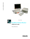
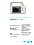
IntelliVue MP2/X2
Se r vi c e G ui de
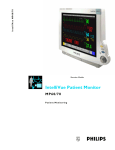
IntelliVue Patient Monitor
MP2/X2
Pa tie n t Monit o ring
Part Number M3002-9301B
4535 641 12541
*M3002-9301B*
Contents
1 Introduction
Who Should Use This Guide
How to Use This Guide
9
9
9
Responsibility of the Manufacturer
10
Passwords
10
Warnings and Cautions
11
2 Theory of Operation
Monitor Theory of Operation
13
13
System Boundaries
14
Hardware Building Blocks
15
Data Flow
19
How does the Support Tool Work with the Monitor
22
Monitor Software Block Diagram
22
Block Diagram Legend
23
3 Testing and Maintenance
27
Introduction
27
Terminology and Definitions
28
Recommended Frequency
29
When to Perform Tests
30
Testing Sequence
34
Visual Inspection
35
Before Each Use
35
After Each Service, Maintenance or Repair Event
35
Power On Test
35
Safety Tests
36
Warnings, Cautions, and Safety Precautions
37
Safety Test Procedures
38
System Test
62
What is a Medical Electrical System?
62
General Requirements for a System
62
System Example
63
System Installation Requirements
64
Required Protective Measures at System Installation
65
System Test Procedure
75
Preventive Maintenance Procedures
Noninvasive Blood Pressure Measurement Calibration
Performance Assurance Tests
Basic Performance Assurance Test
76
76
76
76
3
Full Performance Assurance Test
77
ECG/Resp Performance Test
77
ECG Sync Performance Test
78
SpO2 Performance Test
78
NBP PerformanceTest
79
Invasive Pressure Performance Test
81
Temperature Performance Test
82
M3014A Capnography Extension Performance Tests
82
Microstream CO2 Performance Test
85
Cardiac Output Performance Test
90
Power Loss Alarm Buzzer Performance Test (only if Multi-Port Nurse Call Connector Board is installed)
92
IntelliVue 802.11 Bedside Adapter Communication Test
92
IIT Communication Test
93
Short Range Radio (SRR) Performance Test
94
Reporting of Test Results
95
Carrying Out and Reporting Tests
95
Evaluation of Test Results
97
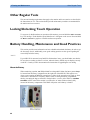
Other Regular Tests
98
Locking/Unlocking Touch Operation
98
Battery Handling, Maintenance and Good Practices
98
About the Battery
Checking the Battery Status
98
99
Battery Status on the Main Screen
100
Battery Status Window
101
Checking Battery Charge
103
Replacing a Battery
103
Optimizing Battery Performance
104
Battery Safety Information
108
After Installation, Testing or Repair
108
4 Troubleshooting
109
Introduction
109
How To Use This Section
109
Who Should Perform Repairs
109
Replacement Level Supported
110
Software Revision Check
110
Software Compatibility Matrix
110
Compatibilty with MMS
111
Compatibility with Information Center
111
Obtaining Replacement Parts
111
Troubleshooting Guide
112
4
Checks for Obvious Problems
112
Checks Before Opening the Instrument
112
Troubleshooting Tables
114
Status Log
130
List of Error Codes
131
Troubleshooting with the Support Tool
131
Troubleshooting the Individual Measurements or Applications
131
5 Repair and Disassembly
133
Who Should Perform Repairs
133
Tools required
133
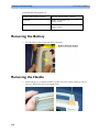
Removing the Battery
134
Removing the Handle
134
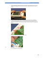
Removing the Side Cover
135
Removing the Display/Exchanging the SRR Board
136
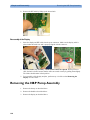
Reassembly of the Display
138
Removing the NBP Pump Assembly
138
Reassembling the NBP pump chassis
140
Exchanging the NBP Pump
142
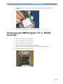
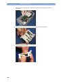
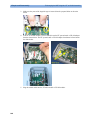
Exchanging the NBP Airguide / IIT or WLAN Assembly
145
Reassembly Procedure
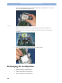
Exchanging the Loudspeaker
147
150
Reassembly Procedure
151
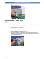
Removing the Power Board
152
Reassembly Procedure
154
Removing the ECG Sync Pulse Out Connector
155
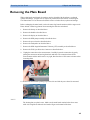
Removing the Main Board
157
Removing the Rear Housing
158
Removing the Measurements
160
Exchanging the Main Housing
161
Exchanging the Silicon Pads
162
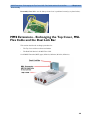
MMS Extensions - Exchanging the Top Cover, MSL Flex Cable and the Dual Link Bar
165
Exchange Procedures
Disassembly Procedures for the M3015A MMS Extension (HW Rev. A)
166
177
Removing the Front Cover
177
Refit Procedures for the MMS Extension
181
Smart Battery Charger LG1480 (M8043A)
183
Cleaning the Air Filter Mats
183
Replacing the Fan
183
6 Parts
187
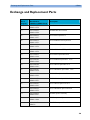
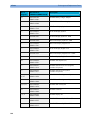
Exchange and Replacement Parts
189
MMS Extension Parts (M3012A, M3014A, M3015A and M3016A)
192
MMS Extension Part Numbers - Release Mechanisms
192
MMS Extension Part Numbers - Top Cover, Flex Cable and Link Bar
193
MMS Extension Part Numbers - Front Bezels
193
Exchange Parts List
195
5
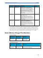
Smart Battery Charger Part Numbers
197
7 Installation Instructions
199
Out-Of-Hospital Transport - Standards Compliance
199
Electromagnetic Interference (SRR)
201
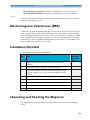
Installation Checklist
201
Unpacking and Checking the Shipment
201
Initial Inspection
202
Claims for Damage
202
Repacking
202
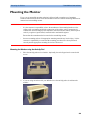
Mounting the Monitor
203
Mounting the Monitor using the Anti-slip Pad
203
Mounting the Monitor using the MMS Mount and Mounting Clamp
205
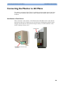
Connecting the Monitor to AC Mains
209
Host Monitor as Power Source
209
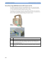
External Power Supply M8023A(Standard with MP2, Optional with X2)
210
Checking Out the Monitor
211
Configuration Tasks
212
Checking Country-Specific Default Settings
212
Setting Altitude, Line Frequency, ECG Cable Colors and Height & Weight Units
213
Configuring the Equipment Label
213
Configuring IP Address, Subnet Mask and Default Gateway
214
Configuration Settings for CSCN Routed Bedside Monitors (RBM)
214
Configuring Routed Bedside Monitors Support
215
Setting the Date and Time
215
Handing Over the Monitor
216
Philips Clinical Network (Wired)
216
Philips IntelliVue Information Center
216
IntelliVue Instrument Telemetry (IIT)
217
Short Range Radio
218
Configuring SRR Channels
218
ECG Sync Pulse
221
MSL Cable Termination
222
8 Site Preparation
Introduction
225
Site Planning
225
Roles & Responsibilities
226
Monitor Site Requirements
228
Space Requirements
228
Environmental Requirements
228
Electrical and Safety Requirements (Customer or Philips)
229
Connecting Non-Medical Devices
230
Philips Medical LAN
6
225
230
9 MP2/X2 Product Structure
Upgrades
231
238
10 Default Settings Appendix
Country-Specific Default Settings
11 Index
241
241
251
7
8
1
Introduction
1
This Service Guide contains technical details for the IntelliVue MP2 Patient Monitor and the
IntelliVue X2.
This guide provides a technical foundation to support effective troubleshooting and repair. It is
not a comprehensive, in-depth explanation of the product architecture or technical
implementation. It offers enough information on the functions and operations of the monitoring
system so that engineers who repair them are better able to understand how it works.
Who Should Use This Guide
This guide is for biomedical engineers or technicians responsible for installing, troubleshooting,
repairing, and maintaining Philips’ patient monitoring systems.
How to Use This Guide
This guide is divided into eight sections. Navigate through the table of contents at the left of the
screen to select the desired topic. Links to other relevant sections are also provided within the
individual topics. In addition, scrolling through the topics with the page up and page down keys
is also possible.
9
1 Introduction
Responsibility of the Manufacturer
Responsibility of the Manufacturer
Philips only considers itself responsible for any effects on safety, EMC, reliability and
performance of the equipment if:
-
assembly operations, extensions, re-adjustments, modifications or repairs are carried out by
persons authorized by Philips, and
-
the electrical installation of the relevant room complies with national standards, and
-
the instrument is used in accordance with the instructions for use.
To ensure safety and EMC, use only those Philips parts and accessories specified for use with
the monitor. If non-Philips parts are used, Philips is not liable for any damage that these parts
may cause to the equipment.
This document contains proprietary information which is protected by copyright. All Rights
Reserved. Reproduction, adaptation, or translation without prior written permission is prohibited,
except as allowed under the copyright laws.
Philips Medizin Systeme Böblingen GmbH
Hewlett-Packard Str. 2
71034 Böblingen, Germany
The information contained in this document is subject to change without notice.
Philips makes no warranty of any kind with regard to this material, including, but not limited to,
the implied warranties or merchantability and fitness for a particular purpose.
Philips shall not be liable for errors contained herein or for incidental or consequential damages
in connection with the furnishing, performance, or use of this material.
Passwords
In order to access different modes within the monitor a password may be required. The
passwords are listed below.
Monitoring Mode: No password required
Configuration Mode: 71034
Demo Mode: 14432
Service Mode: 1345
Consult the configuration guide before making any changes to the monitor configuration.
10
Warnings and Cautions
1 Introduction
Warnings and Cautions
In this guide:
-
A warning alerts you to a potential serious outcome, adverse event or safety hazard. Failure
to observe a warning may result in death or serious injury to the user or patient.
-
A caution alerts you where special care is necessary for the safe and effective use of the
product. Failure to observe a caution may result in minor or moderate personal injury or
damage to the product or other property, and possibly in a remote risk of more serious
injury.
11
1 Introduction
12
Warnings and Cautions
2
Theory of Operation
2
Monitor Theory of Operation
The IntelliVue MP2/X2 Patient Monitor:
-
displays real-time data
-
alarms in the case of patient or equipment problems
-
offers limited data storage and retrieval (trending)
-
interfaces to the Philips Clinical Network and other equipment
The monitor can be configured with various different measurement and interface capabilities.
NOTE
The following descriptions may vary depending on the monitor option purchased.
13
2 Theory of Operation
Monitor Theory of Operation
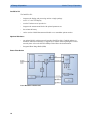
System Boundaries
The following diagram discusses specific boundaries within the overall system with respect to
their openness and real-time requirements:
System Boundaries
Measurement connections
Built-in measurement block
Philips Clinical Network (wired LAN)
connects multiple patient monitors, information centers,
application servers; closed system, only Philips qualified
products (tested and with regulatory approval) are connected,
Philips is responsible for guaranteed real-time functionality and
performance
Philips Clinical Network (wireless)
like Philips Clinical Network (wired) LAN, however due to
current wireless technologies available it has reduced
bandwidth, longer latencies, reduced functionality
Hospital LAN, Internet
Standard Network, not under Philips control, no guaranteed
service, no real-time requirements
14
Monitor Theory of Operation
2 Theory of Operation
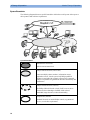
Hardware Building Blocks
The following hardware building blocks make up the monitoring system:
MP2/X2 Hardware Building Blocks
IntelliVue MP2
The MP2 monitor:
-
integrates the display and processing unit into a single package
-
uses a 3.5” color TFT display
-
uses the Touchscreen as input device
-
integrates the measurement block with optional parameter sets
-
has an internal battery
-
standalone patient monitor
15
2 Theory of Operation
Monitor Theory of Operation
IntelliVue X2
The IntelliVue X2:
-
integrates the display and processing unit into a single package
-
uses a 3.5” color TFT display
-
uses the Touchscreen as input device
-
integrates the measurement block with optional parameter sets
-
has an internal battery
-
can be used as a Multi-Measurement Module or as a standalone patient monitor
Optional Hardware
-
An optional built-in wireless network interface (IntelliVue 802.11 Bedside Adapter or
IntelliVue Instrument Telemetry) is supported. For further details regarding the wireless
network please refer to the M3185A Philips Clinical Network documentation.
-
Integrated Short Range Radio (SRR)
Power Distribution
Power Distribution Architecture
16
Monitor Theory of Operation
2 Theory of Operation
The DC/DC converter transforms the DC power (36-60 V DC range) coming from the MSL plug
into a 16 V DC source and isolates the monitoring system from the DC MSL.
The 16V DC is distributed via the Power Board to the battery charging circuit and to the main
board.
The power is used to charge the battery and supply the monitoring system. As soon as the DC
power source is disconnected, the battery starts and keeps the system powered (battery mode).
The main board contains power supply circuits, which convert the 16 V DC into several voltages
supplying the particular components of the monitoring system.
The realtime clock and the buffered RAM is supplied with cont. 3.6 V DC power, provided
either by the 16 V DC system power or by the battery power and converted to 3.6 V DC.
The CPU board has an MPC852 MHz processor in the patient monitor that provides a number of
on-chip, configurable interfaces. An array of fast UARTS with configurable protocol options are
implemented in an ASIC (along with other system functions such as independent watchdogs,
video, etc.), providing interfacing capabilities to integrated measurements. The main board
contains additional video hardware.
The CPU provides a LAN interface to connect to the Philips Clinical Network (Ethernet).
System Interfaces
The LAN interface on the Measurement Link (MSL) is used as the network interface.
17
2 Theory of Operation
Monitor Theory of Operation
Compatible Devices
M3012A, M3014A, M3015A, M3016A MMS Extensions
NOTE
The MMS Extensions are not supported if the IntelliVue MP2/X2 is powered from the internal
battery. Although they can still be attached, they will not function in this case.
18
Monitor Theory of Operation
2 Theory of Operation
Data Flow
The following diagram shows how data is passed through the monitoring system. The individual
stages of data flow are explained below.
Display
and User
Interface
Data
Acquisition
Data
Provider
Service
Applications
Persistent
Data
Storage
Data
Output
Data Flow
Data Acquisition
Monitoring data (for example patient measurement data in the form of waves, numerics and
alerts) is acquired from a variety of sources:
-
Measurement Block
The integrated measurements convert patient signals to digital data and apply measurement
algorithms to analyze the signals.
-
External measurement devices
Data can be also acquired from devices connected to the monitor. Software modules
dedicated to such specific devices convert the data received from an external device to the
format used internally.
-
Server systems on the Philips Clinical Network
To enable networked applications, data can be acquired from server systems attached to the
Philips Clinical Network, for example a Philips Information Center
19
2 Theory of Operation
Monitor Theory of Operation
Data Provider System Service
All data that is acquired from integrated measurements or external measurement devices is
temporarily stored by a dedicated data provider system service. All monitor applications use this
central service to access the data in a consistent and synchronized way rather than talking to the
interfaces directly.
This service makes the applications independent of the actual type of data acquisition device.
The amount of data stored in the data provider system service varies for the different data types.
For example several seconds of wave forms and the full set of current numerical values are
temporarily stored in RAM.
Persistent Data Storage System Service
Some applications require storage of data over longer periods of time. They can use the
persistent data storage system service. Dependent on the application requirements, this service
can store data either in battery backed-up (buffered) memory or in flash memory. The buffered
memory will lose its contents if the monitor is without power (not connected to mains) for an
extended period of time. The flash memory does not lose its contents.
The trend application for example stores vital signs data in a combination of flash memory and
buffered memory, while the system configuration information (profiles) is kept purely in flash
memory.
Display and User Interface Service
Applications can use high level commands to display monitoring data or status and command
windows on the internal LCD panel. These commands are interpreted by the display manager
application. This application controls the dedicated video hardware which includes video
memory and a special hardware in the ASIC.
User input is acquired from the touchscreen. The system software makes sure that the user input
is directed to the application which has the operating focus.
Monitor Applications
The monitor applications provide additional system functionality over the basic measurement
and monitoring capabilities. This includes for example trending, report generating, event storage
or derived measurements.
In general, the monitor applications use the data provider system service to access the
measurement data. Application interfaces to the other system services allow the application to
visualize data, to store data over extended periods of time or to output data to other devices.
20
Monitor Theory of Operation
2 Theory of Operation
Internal LAN (Measurement Link)
The MP2/X2 communicates using an IEEE802.3 Ethernet LAN in the Measurement Link
(MSL). This network is used to distribute data between the components, for example:
-
Digitized patient signals including wave data, numerical data and status information
(typically from the measurement server to a display unit)
-
Control data representing user interactions (typically from the display unit to a measurement
server)
-
Shared data structures, for example representing patient demographical data and global
configuration items
The internal LAN allows plug and play configuration of the monitoring system. The system
automatically detects plugging or unplugging of measurement servers and configures the system
accordingly.
The components on the internal LAN are time-synchronized to keep signal data consistent in the
system. Dedicated hardware support for synchronization eliminates any latency of the network
driver software.
The integrated LAN provides deterministic bandwidth allocation/reservation mechanisms so that
the real-time characteristic of signal data and control data exchange is guaranteed. This applies
to the data flow from the X2 to the host monitor (for example measurement signal data) and the
data flow from the host monitor to an X2 (for example to feed data to a recorder module).
Philips Clinical Network
The monitoring system may be connected to the Philips Clinical Network, for example to
provide central monitoring capabilities or other network services. This connection may be
through a normal wired connection.
After configuration, the monitoring system sends the digitized patient signals including wave
data, numerical data and status information onto the network. Control data representing user
interactions can be exchanged between the monitoring system and a central station
bi-directionally.
For plug and play operation, the monitoring system uses the standard BootP protocol to
automatically acquire a network address.
21
2 Theory of Operation
Monitor Theory of Operation
How does the Support Tool Work with the Monitor
The support tool is a Windows application typically installed on the laptop of a customer
engineer or a biomedical engineer working in the customer’s own service department.
The purpose of the support tool is to upgrade, configure and diagnose all monitoring components
in the system over the network.
The service protocol developed for this purpose uses a raw access to the devices without the
need for IP addresses etc. over a standard customer network installation, so that even defective
devices can be upgraded as long as the few kBytes of initial boot code are working. The boot
code itself can also be upgraded using the same protocol.
The tool allows access to internal service information and to serial numbers. It can be remotecontrolled, for example via a dial-up connection from a response center, provided the proper
infrastructure is in place.
For details see the Instructions for Use for the Support Tool.
Monitor Software Block Diagram
The figure below shows the functional block diagram for the monitoring system. A legend
explaining terms and diagram elements follows. The information below varies depending on the
purchased monitor options.
Functional Block Diagram
22
Monitor Theory of Operation
2 Theory of Operation
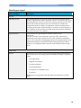
Block Diagram Legend
Functional Block
Description
Services
Operating System
The Operating System (OS) provides a layer of isolation between the specific
hardware implementation and the application software. The OS performs system
checks and allocates resources to ensure safe operation when the system is first
started. This includes internal self-tests on several hardware modules and
configuration checks for validity of configuration with the operating software.
During normal operation, the OS continues to run checks on system integrity. If
error conditions are detected the OS will halt monitoring operations and inform
the operator about the error condition.
System Services
The System Services provide generic common system services.
In particular:
They use a real-time clock component to track time. They synchronize to
network time sources and verify the accuracy of the system time information.
They are also responsible for managing persistent user configuration data for all
Measurement parameters and IntelliVue Patient Monitoring System software
modules. User configuration data is stored in a non-volatile read/write storage
device
Applications
Reports
The Reports Service retrieves current and stored physiological data and status
data to format reports for printing paper documentation. Examples of supported
reports:
-
Vital Signs Report
-
Graphical Trend Report
-
Event Review Report
-
Event Episode Report
-
ECG Report (12 Lead/Multi-Lead)
-
Test Report
The Reports service generates report data which can be printed on a central
printer.
23
2 Theory of Operation
Monitor Theory of Operation
Functional Block
Description
Alarm
The Alarm Service contains logic that prioritizes alarm conditions that are
generated by IntelliVue Patient Monitoring System software modules. Visual
alarm signals (messages) are displayed at the top of the IntelliVue Patient
Monitoring System display and alarm sounds are generated by a loudspeaker.
Alarm conditions may be generated when a physiological parameter exceeds
preselected alarm limits or when a physiological parameter or any other software
module reports an inoperative status (technical alarm, for example, the ECG
leads may have fallen off the patient). The Alarm service manages the alarm
inactivation states, for example suspension of alarms, silencing of alarms, and
alarm reminder. Alarm signals may also be configured as latching (alarm signals
are issued until they are acknowledged by the operator, even when the alarm
condition is no longer true). The Alarm service controls the visual alarm signals
(alarm lamps).
Trend
The Trend service stores the sample values of physiological data and status data
with a resolution of 12 seconds, 1 minute or 5 minutes for a period of up to 48
hours. The data is kept in battery buffered read/write storage and flash memory
devices to be preserved across power failures. The stored data is protected via
consistency checks and checksums. When a new patient is admitted, the trend
database erases all data of the previous patient.
ADT
The ADT (Admit/Discharge/Transmit) service maintains the patient
demographics information. The operator may admit a new patient, discharge the
old patient and enter or modify the patient demographics.
Calc Param
The Calc Param (Calculated Parameters) application performs calculations on
physiological numerical values to derive calculated parameters like Temperature
Difference.
Interface Managers
MDSE
The MDSE (Medical Data Service Element) Interface Manager is responsible
for the exchange of real-time data between the IntelliVue Patient Monitoring
System display unit and the Measurement parameters and other devices attached
to the network. MDSE establishes and maintains a data communication link
between the devices. It provides configuration information about the remote
device to applications in the local device and it allows the exchange of
measurement data and status information between the devices.
Printer
The Printer Interface Manager provides a high level interface to a printer. It
provides means to:
-
establish a connection to the printer
-
transfer data to the printer
-
get status of the printer
-
close connection to the printer
The Printer Interface Manager also supervises the connection to the printer and
whether the printer accepts data (for example paper out). The Printer Interface
Manager notifies the operator in such cases.
24
Monitor Theory of Operation
2 Theory of Operation
Functional Block
Description
Display & Operator
Interface
The Display and Operator Interface Manager performs the following tasks:
-
Screen presentation of real-time and stored physiological measurement data,
alarm condition data and status information received from the MDSE
interface manager, the Alarm service or other IntelliVue Patient Monitoring
System modules
-
Screen presentation of operating controls (control windows)
-
Processing of operating control commands received from HIF Control
interface. The module verifies and interprets the received commands and
forwards them to other software modules of the IntelliVue Patient
Monitoring System display unit or measurement parameters.
-
Sound generation (issues audible alarm signals and generates audible
information signals, for example QRS and SpO2 tones, operator audible
feedback)
Interfaces
LAN
The LAN interface implements the physical layer of IEEE 802.3. The LAN
interface performs Manchester encoding/decoding, receive clock recovery,
transmit pulse shaping, jabber, link integrity testing, reverse polarity
detection/correction, electrical isolation, and ESD protection. Electronically
separated interfaces are used for communication to the Measurement parameters
and to the network.
Display Controller
The Display Controller Interface consists of a video controller, video RAM and
the controlling software. The Display Controller interface processes the high
level display commands (character and graphic generation, wave drawing) and
translates them into pixels, which are written into the video RAM where the
video controller chip generates the video synchronization signals and the pixel
stream for the Color LCD Display.
HIF Control
The HIF (Human Interface Control) interface scans the Human Interface devices
for operator controls (Touch Screen), formats the collected data and sends it to
the display and Operating Interface.
Sync Out (ECG)
A pulse signal is provided on the Sync Out connector to allow synchronisation
with other medical devices.
IIT
The built-in IIT module allows operation of the MP2/X2 monitors within
IntelliVue Instrument Telemetry Infrastructure.
WLAN
The built-in WLAN interface allows wireless operation of the X2/MP2 monitors
with the IntelliVue 802.11 Bedside Adapter
SRR
The built-in SRR interface allows wireless communication of the MP2/X2
monitors with an IntelliVue Instrument Telemetry Transceiver.
MSL
All components of the monitoring system communicate using an IEEE802.3/
Ethernet LAN in the Measurement Link (MSL). This network is used to
distribute data between the components
25
3
Testing and Maintenance
3
Introduction
This chapter provides a checklist of the testing and maintenance procedures to ensure the
performance and safety of the monitor and the MMS Extensions. For testing of the host monitor
and the Flexible Module Rack (FMS), see the Service Guide of the host monitor.
These tests must be performed only by qualified personnel certified by the responsible
organization. Qualifications required are: training on the subject, knowledge, experience and
acquaintance with the relevant technologies, standards and local regulations. The personnel
assessing safety must be able to recognize possible consequences and risks arising from
non-conforming equipment.
All recurring safety and performance assurance tests must be performed under equal
environmental conditions to be comparable.
Testing of the MP2/X2 may be performed either on the MP2/X2 (with external power supply)
directly or (for the X2) on the host monitor.
Preventive Maintenance refers specifically to the series of tests required to make sure the
measurement results are accurate. The accuracy and performance procedures are designed to be
completed as specified in the following sections or when readings are in question.
For detailed instructions on the maintenance and cleaning of the monitor and its accessories, see
Care and Cleaning, Using Batteries and Maintenance and Troubleshooting in the monitor's
Instructions for Use.
27
3 Testing and Maintenance
Terminology and Definitions
Terminology and Definitions
The following terms and definitions are used throughout this chapter and taken from the
international standards IEC 60601-1, IEC 60601-1-1 and IEC 62353.
28
-
Medical System: a medical electrical system is a combination of at least one medical
electrical device and other electrical equipment, interconnected by functional connection or
use of a multiple portable socket-outlet.
-
Patient Vicinity: any area in which intentional or unintentional contact can occur between
the patient and parts of the medical system or between the patient and other persons who
have had contact with parts of the medical system. The patient vicinity is defined anywhere
within 1.5m (5 feet) of the perimeter of the patient's bed and 2.5m (8.2 feet) from the floor.
-
Separation Device/Transformer: a component or arrangement of components with input
parts and output parts that, for safety reasons, prevent a transfer of unwanted voltage or
current between parts of a medical system.
-
Multiple Portable Socket-Outlet: a combination of two or more socket-outlets intended to
be connected to or integrated with flexible cables or cords, which can easily be moved from
one place to another while connected to the power mains.
-
Functional Connection: an electrical connection for transfer of signals and/or power.
-
Tests: Safety or Performance Assurance test procedures which may consist of several steps.
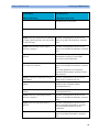
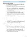
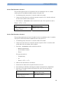
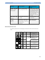
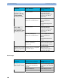
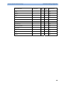
Recommended Frequency
3 Testing and Maintenance
Recommended Frequency
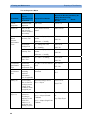
Perform the procedures as indicated in the suggested testing timetable. These timetable
recommendations do not supersede local requirements.
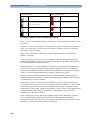
Table 1: Suggested Testing Timetable
Tests
Frequency
Preventive Maintenance*
Other Regular Tests
NBP Performance
Once every two years, or more often if
specified by local laws.
Microstream CO2 Calibration
Once a year or after 4000 hours of
continuous use and following any
instrument repairs or the replacement of
any instrument parts.
Visual Inspection
Before each use.
Power On Test
Performance Assurance
Tests
ECG/Resp Performance
ECG Sync Pulse Performance
SpO2 Performance
NBP Performance
Once every two years, or if you suspect
the measurement is incorrect, except
Mainstream CO2 Accuracy Check,
Sidestream CO2 Accuracy Check and
Flow Check - required once a year.
Invasive Pressure Performance
Temperature Accuracy
M3014A Capnography Extension
Performance Tests
Microstream CO2 Performance Test
C.O. Performance Test
Safety
Tests
Visual
Electrical
Visual Inspection
After each service event.
Protective Earth
Patient Leakage Current
Once every two years and after repairs
where the power supply has been
removed or replaced or the monitor has
been damaged by impact.
System Test
Once every two years
Equipment Leakage Current
*M3015A with the old hardware Rev. A (i.e. Serial No. DE020xxxxx) also require the CO2
pump/CO2 scrubber replacement procedure. This is required every three years or after 15000
operating hours.
29
3 Testing and Maintenance
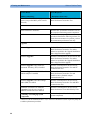
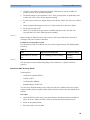
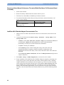
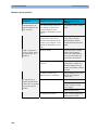
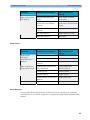
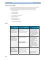
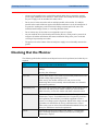
When to Perform Tests
When to Perform Tests
This table tells you when to perform specific tests.The corresponding test procedures are
described in the following sections All tests listed below must be performed on the monitor
itself and its host monitor.
When to perform tests
Service Event
Tests Required
(When performing...
...Complete these tests)
Installation
Installation of a monitor in combination with
a medical or non-medical device connected to
the same multiple socket outlet.
Perform Visual Inspection, Power On and
System Tests
Installation of monitor with IntelliVue
Instrument Telemetry (IIT)
Perform Visual Inspection, Power On and IIT
communication test
Installation of monitor with IntelliVue
802.11 Bedside Adapter
Perform Visual Inspection, Power On and
IntelliVue 802.11 Bedside Adapter
Communication Test
Installation of a monitor with Short Range
Radio (SRR)
Perform Visual Inspection, Power On and SRR
communication test
Installation of networked monitor (LAN)
Perform Visual Inspection and Power On Test
Preventive Maintenance
Preventive Maintenance*
Perform preventive maintenance tests and
procedures:
-
NBP calibration
-
Microstream CO2 calibration
Other Regular Tests and Tasks
Visual Inspection
30
Perform Visual Inspection test block
When to Perform Tests
3 Testing and Maintenance
Service Event
Tests Required
(When performing...
...Complete these tests)
Power On Test
Perform Power On test block
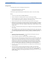
Repairs
Repairs where the monitor has been damaged
by impact, liquid ingression, fire, short circuit
or electrical surge.
Perform Visual Inspection, Power On, all
Safety Tests and Full Performance Assurance
Tests
Repairs where the MSL power board is
removed or replaced
Perform Visual Inspection, Power On, all
Safety Tests and Basic Performance Assurance
Test
Repairs where the main board has been
replaced.
Perform Visual Inspection, Power On, Basic
Performance Assurance Test and NBP
Accuracy Test and Calibration.
Repairs where the measurement block has
been removed or replaced
Perform Visual Inspection, Power On, all
Safety Tests and Basic Performance Assurance
Test.
If a certain parameter seems suspicious,
perform Full Performance Assurance Test for
this parameter.
Repairs of IntelliVue Instrument Telemetry
(IIT) Module
Perform Visual Inspection, Power On Test
Block and IIT communication test
Repairs of IntelliVue 802.11 Bedside
Adapter
Perform Visual Inspection, Power On and
IntelliVue 802.11 Bedside Adapter
Communication Test
Repairs of Short Range Radio (SRR)
Interface
Perform Visual Inspection, Power On and SRR
Communication Test
Repairs where the rear housing has been
removed or replaced.
Perform Visual Inspection, Power On, all
Safety Tests and Basic Performance Assurance
Test.
Repairs where the NBP pump has been
replaced
Perform Visual Inspection, Power On, all
Safety Tests, Basic Performance Assurance
Test and NBP Performance Test and
Calibration
Repairs of the M3015A MMS Extension
Perform Visual Inspection, Power On, all
Safety Tests, Basic Performance Assurance
Test
31
3 Testing and Maintenance
When to Perform Tests
Service Event
Tests Required
(When performing...
...Complete these tests)
All other IntelliVue Monitoring System
repairs (except when MSL power board is
removed)
Perform Visual Inspection, Power On Test and
Basic Performance Assurance Test
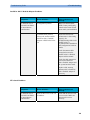
Performance Assurance
Basic Performance Assurance
Perform basic performance assurance tests for
the respective monitoring system component.
Full Performance Assurance
Perform all accuracy and performance test
procedures listed in the following sections. If a
particular measurement is in question, perform
the measurement performance test only.
Upgrades
Software Upgrades
Perform Visual Inspection, Power On Test and
Basic Performance Assurance Test unless
otherwise specified in the Upgrade Installation
Notes shipped with the upgrade.
Hardware Upgrades
Perform Visual Inspection, Power On Test and
Basic Performance Assurance Test unless
otherwise specified in the Upgrade Installation
Notes shipped with the upgrade.
Hardware Upgrades where IntelliVue
Instrument Telemetry (IIT) is installed
Perform Visual Inspection, Power On Test,
Basic Performance Assurance Test and IIT
communication Test
Hardware Upgrades where IntelliVue 802.11
Bedside Adapter is installed
Perform Visual Inspection, Power On Test,
Basic Performance Assurance Test and
IntelliVue 802.11 Bedside Adapter
Communication Test
Hardware Upgrades where Short Range
Radio (SRR) is installed
Perform Visual Inspection, Power On Test,
Basic Performance Assurance Test and SRR
communication Test
Installation of Interfaces or Hardware
Upgrades where the power supply or
parameter boards need to be removed.
Perform Visual Inspection, Power On Test,
Basic Performance Tests and all Safety Tests
Combining or Exchanging System
Components
Perform the System Test for the respective
system components
*M3015A with the old hardware Rev. A (i.e. Serial No. DE020xxxxx) also require the pump and
scrubber replacement procedures.
32
When to Perform Tests
3 Testing and Maintenance
NOTE
It is the responsibility of the facility operator or their designee to obtain reference values for
recurring safety and system tests. These reference values are the results of the first test cycles
after an installation. You may also purchase this service from Philips.
33
3 Testing and Maintenance
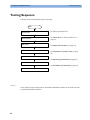
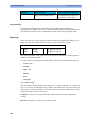
Testing Sequence
Testing Sequence
Summary of the recommended sequence of testing:
Start
See When to Perform Tests
Select the test
Visual Inspection
Safety Tests
Performance Tests
See Visual Test (see "Before Each Use" on
page 35).
See Safety Test Procedures (on page 38).
See Performance Assurance Tests (on page
76).
Reporting of Results
See Reporting of Test Results (on page 95)
Evaluation of Results
See Evaluation of Test Results (on page 97)
Check and prepare for normal use
NOTE
If any single test fails, testing must be discontinued immediately and the device under test must
be repaired or labeled as defective.
34
Visual Inspection
3 Testing and Maintenance
Visual Inspection
Before Each Use
Check all exterior housings for cracks and damage. Check the condition of all external cables,
especially for splits or cracks and signs of twisting. If serious damage is evident, the cable should
be replaced immediately. Check that all mountings are correctly installed and secure. Refer to
the instructions that accompany the relevant mounting solution.
After Each Service, Maintenance or Repair Event
Ensure all fuses accessible from the outside comply with the manufacturer’s specification.
Check:
-
the integrity of mechanical parts, internally and externally.
-
any damage or contamination, internally and externally
-
that no loose parts or foreign bodies remain in the device after servicing or repair.
-
the integrity of all relevant accessories.
Power On Test
1. Connect the monitoring system to mains and switch it on. This includes connected displays
and MMS Extensions.
2. Make sure that all steps listed in the table Initial Instrument Boot Phase in the
Troubleshooting section are completed successfully and that an ECG wave appears on the
screen.
The expected test result is pass: the monitor boots up and displays an ECG wave. The wave
might be a flat line if no simulator is attached.
35
3 Testing and Maintenance
Safety Tests
Safety Tests
The following safety test needs to be performed on the monitoring system:
-
applied part leakage current
-
system test (if required)
Safety test requirements are set according to international standards, their national deviations and
specific local requirements. The safety tests detailed in this Service Guide are derived from
international standards but may not be sufficient to meet local requirements. We recommend that
you file the results of safety tests. This may help to identify a problem early particularly if the
test results deteriorate over a period of time.
Each individual piece of equipment of the monitoring system which has its own connection to
mains or which can be connected or disconnected from mains without the use of a tool must be
tested individually. The monitoring system as a whole must be tested according to the System
Test (on page 61) procedure.
Accessories of the monitoring system which can affect the safety of the equipment under test or
the results of the safety test must be included in the tests and documented.
Electrical safety tests for MP2/X2 can be performed either on the individual device (MP2 or X2)
connected to the external power supply or on a connected host monitor (e.g. MP20-90). Note that
if the electrical safety tests are performed with a host monitor the protective earth resistance and
equipment leakage current come mainly from the host monitor. The earthing of MP2/X2 is for
functional purposes and does not provide protection against electric shock. The protection
against electric shock in this device is provided by double and/or reinforced insulation. The
protective earth resistance and equipment leakage current measurements for MP2/X2 are
optional.
36
Safety Tests
3 Testing and Maintenance
Warnings, Cautions, and Safety Precautions
-
These tests are well established procedures of detecting abnormalities that, if undetected,
could result in danger to either the patient or the operator.
-
Disconnect the device under test from the patient before performing safety tests.
-
Disconnect the device under test from mains before performing safety tests. If this is not
possible, ensure that the performance of these tests does not result in danger to the safety
analyzer operator, patients or other individuals.
-
Test equipment (for example, a Safety Analyzer) is required to perform the safety tests.
Please refer to Annex C of IEC/EN 62353 for exact requirements for the measurement
equipment and for measurement circuits for protective earth resistance and leakage currents.
Refer to the documentation that accompanies the test equipment. Only certified technicians
should perform safety testing.
-
The consistent use of a Safety Analyzer as a routine step in closing a repair or upgrade is
emphasized as a mandatory step to maintain user and patient safety. You can also use the
Safety Analyzer as a troubleshooting tool to detect abnormalities of line voltage and
grounding plus total current loads.
-
During safety testing, mains voltage and electrical currents are applied to the device under
test. Ensure that there are no open electrical conductive parts during the performance of
these tests. Avoid that users, patients or other individuals come into contact with touch
voltage.
-
For Europe and Asia/Pacific, the monitor complies with:
IEC60601-1:1988 + A1:1991 + A2:1995 = EN60601-1:1990 +A1:1993 + A2:1995
IEC60601-1-1:2000
For USA, the monitor complies with:
UL60601-1
For Canada, CAN/CSA C22.2#601.1-M90
-
Local regulations supersede the testing requirements listed in this chapter.
-
If a non-medical electrical device is connected to a medical electrical device, the resulting
medical electrical system must comply with IEC/EN 60601-1-1.
-
Perform safety tests as described on the following pages.
37
3 Testing and Maintenance
Safety Tests
Safety Test Procedures
Use the test procedures outlined here only for verifying safe installation or service of the
product. The setups used for these tests and the acceptable ranges of values are derived from
local and international standards but may not be equivalent. These tests are not a substitute for
local safety testing where it is required for an installation or a service event. If using an approved
safety tester, perform the tests in accordance with the information provided by the manufacturer
of the tester and in accordance with your local regulations, for example IEC/EN 60601-1,
UL60601-1 (US), IEC/EN 62353, and IEC/EN 60601-1-1. The safety tester should print results
as detailed in this chapter, together with other data.
Please refer to Annex C of IEC/EN 62353 for requirements for the measurement equipment and
for measurement circuits for protective earth resistance and leakage currents.
The following symbols are used in the diagrams illustrating the safety tests:
Supply mains
L, N
.........
Supply mains terminals
Protective earth
PE
Protective earth terminal
Mains part
Applied part
F-type applied part
Measuring device
Resistance measuring
device
Connection to accessible
conductive parts
Optional connection
CAUTION
After each service, maintenance or repair event:
Ensure all fuses accessible from the outside comply with the manufacturer’s specification.
Check:
38
-
the integrity of mechanical parts, internally and externally.
-
any damage or contamination, internally and externally.
-
that no loose parts or foreign bodies remain in the device after servicing or repair.
-
the integrity of all relevant accessories.
Safety Tests
3 Testing and Maintenance
Hints for Correct Performance of Safety Tests
-
Perform a visual inspection on all detachable power cords used with the monitoring system
and include these in all safety test procedures.
-
Connection lines such as data lines or functional earth conductors may appear to act like
protective earth connections. These may lead to incorrect measurements and need to be
considered during testing. If necessary, unplug these connections.
-
Position all cables and cords in such a manner that they do not influence the safety tests.
-
Measurement of insulation resistance is not required.
Guideline for Performance of Safety Tests
Connect the detachable power cord of the device under test to the safety analyzer's test mains
port. For testing the detachable power cord protective earth, use the setup provided with your
safety analyzer. For testing the equipment leakage current and the applied part leakage current,
connect all applied parts to the safety analyzer using the appropriate patient lead or adapter
cable. For the ECG parameter all ten ECG-leads need to be connected to the safety analyzer. If
necessary, use an adapter cable to connect all ten ECG-leads. If necessary, repeat the safety test
procedure until all available applied parts have been tested. Refer to the documentation that
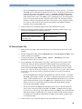
accompanies the safety analyzer for further details on how to set up and perform the test.
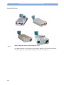
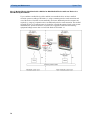
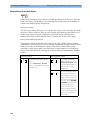
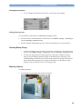
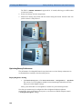
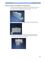
Detachable Power Cord Protective Earth Test - Setup Example
Equipment Leakage Current and Applied Part Current Test - Setup Example
NOTE
The above graphics resemble the Metron QA-90 setup and are protected by copyright. Copyright
owned by Fluke (Metron).
39
3 Testing and Maintenance
Safety Tests
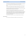
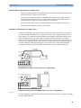
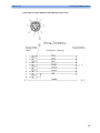
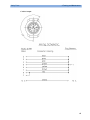
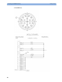
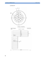
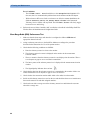
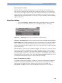
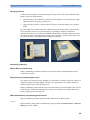
Safety Test Adapter Cable - Schematics
The following graphics provide schematics of safety test (patient lead) adapter cables which can
be used for electrical safety testing. These schematics can also be used as a guideline for making
your own safety test adapter cables. Alternatively, other methods to make safety test adapter
cables can be used, e.g. using a modified accessory cable.
NOTE
You may not need all of the cables displayed below for electrical safety testing of your
respective monitor.
ECG:
40
Safety Tests
3 Testing and Maintenance
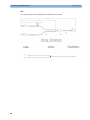
SpO2 (MP2/X2, MP5, M3001A & M1020B #A01, #A02, #A03):
41
3 Testing and Maintenance
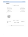
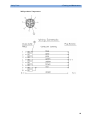
SpO2 (M1020A):
42
Safety Tests
Safety Tests
3 Testing and Maintenance
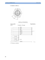
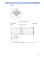
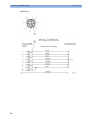
Invasive Pressure:
43
3 Testing and Maintenance
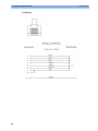
M1006B #C01:
Temperature:
44
Safety Tests
Safety Tests
3 Testing and Maintenance
CO2 (MP5, M3014A):
45
3 Testing and Maintenance
CO2 (M1016A, M3016A):
4 = all resistors 120 KOhm
46
Safety Tests
Safety Tests
3 Testing and Maintenance
Cardiac Output:
47
3 Testing and Maintenance
BIS:
Use Clamp Adapter Cable and M1034-61650 BIS sensor simulator.
48
Safety Tests
Safety Tests
3 Testing and Maintenance
VueLink:
4 = 220 Ohm
49
3 Testing and Maintenance
IntelliBridge:
50
Safety Tests
Safety Tests
3 Testing and Maintenance
EEG:
51
3 Testing and Maintenance
SvO2 (M1021A):
52
Safety Tests
Safety Tests
3 Testing and Maintenance
ScvO2 (M1011A):
53
3 Testing and Maintenance
tcpO2/tcpCO2:
54
Safety Tests
Safety Tests
3 Testing and Maintenance
MP5 predicitive Temperature:
55
3 Testing and Maintenance
MP5 TAAP:
56
Safety Tests
Safety Tests
3 Testing and Maintenance
S(1): Detachable Power Cord Protective Earth Test (optional)
This test can be performed upon request by the customer.
Test to perform:
Use an Ohmmeter to measure the earth wire resistance of the detachable power cord.
This safety test is based on IEC/EN 60601-1, IEC/EN 62353, UL2601-1 Ed. 2/UL60601-1:2003
and CSA 601.1-M90.
Report the highest value (X1).
Test
Expected test results
Protective Earth Resistance Test
X1 <= 100mOhms
NOTE
-
If the protective earth resistance test fails, testing must be discontinued immediately and the
device under test must be repaired or labeled as defective.
-
Flex the power cord during the protective earth resistance test to evaluate its integrity. If it
does not pass the test, exchange the power cord.
-
The functional earth conductor is required for EMC purposes. It has no protective function
against electrical shock. The protection against electrical shock is provided by double and/or
reinforced insulation.
S(2): Equipment Leakage Current Test - Normal Condition (optional)
This test can be performed upon request by the customer.
Test to perform:
57
3 Testing and Maintenance
Safety Tests
Measuring circuit for the measurement of Equipment Leakage Current - Direct method
according to IEC/EN 62353.
This test measures the functional earth leakage current. It tests normal and reversed polarity.
Perform the test with S1 closed (Normal Condition). There is no exposed metal part or functional
earth connector which can be used to attach a test lead.
This safety test is based on IEC/EN 60601-1, IEC/EN 62353, UL2601-1 Ed. 2/UL60601-1:2003
and CSA 601.1-M90.
Report the highest value (X1).
Test
Expected test results
Equipment Leakage Current Test
(Normal Condition - with mains
cable)
X1 <= 100μA
NOTE
All values for current and voltage are the root mean square (r.m.s.) values, unless otherwise
stated.
S(3): Equipment Leakage Current Test - Single Fault Condition (optional)
This test can be performed upon request by the customer.
Test to perform:
58
Safety Tests
3 Testing and Maintenance
Measuring circuit for the measurement of Equipment Leakage Current - Direct method
according to IEC/EN 62353.
This test measures the functional earth leakage current. It tests normal and reversed polarity.
Perform the test with S1 open (Single Fault Condition). There is no exposed metal part or
functional earth connector which can be used to attach a test lead.
This safety test is based on IEC/EN 60601-1, IEC/EN 62353, UL2601-1 Ed. 2/UL60601-1:2003
and CSA 601.1-M90.
Report the highest value (X2).
Test
Expected test results
Equipment Leakage Current Test
(Single Fault Condition - with mains
cable)
X2 <= 300μA
NOTE
All values for current and voltage are the root mean square (r.m.s.) values, unless otherwise
stated.
59
3 Testing and Maintenance
Safety Tests
S(4): Applied Part Leakage Current - Mains on Applied Part
NOTE
During measurement of the Applied Part Leakage Current it is possible that the measured current
can exceed the allowed limit (per IEC/EN 60601-1 or IEC/EN 62353).
This can occur when the safety tester is connected to the invasive blood pressure and
temperature connectors at the same time during the applied leakage current measurement.
The connectors for the invasive blood pressure and temperature are independently functioning
connectors.
Although there are individual connectors on the front end, internally those parameters use the
same electrical insulation interface and are hardwired to each other. This results in an electrical
short of those connectors during measurement if a test current is applied simultaneously.
Therefore this should be avoided.
Due to the combined insulation interface, it is sufficient to connect to only one parameter
interface (that is, Invasive Blood Pressure or Temperature) of the invasive blood
pressure/temperature measurement block. This avoids a short and the potential of exceeding the
limit for the current.
Test to perform:
60
Safety Tests
3 Testing and Maintenance
Measuring circuit for the measurement of Applied Part Leakage Current - Direct method
according to IEC/EN 62353.
This test measures applied part leakage current from applied part to earth caused by external
main voltage on the applied part. Each polarity combination possible shall be tested. This test is
applicable for ECG measurement inputs. There is no exposed metal part or functional earth
connector which can be used to attach a test lead.
This safety test is based on IEC/EN 60601-1, IEC/EN 62353, UL2601-1 Ed. 2/UL60601-1:2003
and CSA 601.1-M90.
For measurement limits and test voltage, refer to test block Safety (4), Test and Inspection
Matrix.
Report the highest value. (X1).
Test
Expected test results
Applied Part Leakage Current Test
(Single Fault Condition - mains on
applied part)
X1 <= 50μA
NOTE
All values for current and voltage are the root mean square (r.m.s.) values, unless otherwise
stated.
61
3 Testing and Maintenance
System Test
System Test
After mounting and setting up a system, perform system safety tests according to IEC/EN
60601-1-1.
What is a Medical Electrical System?
A medical electrical system is a combination of at least one medical electrical piece of
equipment and other electrical equipment, interconnected by functional connection or use of a
multiple portable socket-outlet.
-
Devices forming a medical electrical system must comply with IEC/EN 60601-1-1.
-
Any electrical device such as IT equipment that is connected to the medical electrical
equipment must comply with IEC/EN 60601-1-1 and be tested accordingly.
General Requirements for a System
After installation or subsequent modification, a system must comply with the requirements of the
system standard IEC/EN 60601-1-1. Compliance is checked by inspection, testing or analysis, as
specified in the IEC/EN 60601-1-1 or in this book.
Medical electrical equipment must comply with the requirements of the general standard IEC/EN
60601-1, its relevant particular standards and specific national deviations. Non-medical electrical
equipment shall comply with IEC safety standards that are relevant to that equipment.
Relevant standards for some non-medical electrical equipment may have limits for equipment
leakage currents higher than required by the standard IEC/EN 60601-1-1. These higher limits are
acceptable only outside the patient environment. It is essential to reduce equipment leakage
currents to values specified in IEC 60601-1 when non-medical electrical equipment is to be used
within the patient environment.
62
System Test
3 Testing and Maintenance
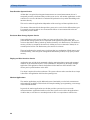
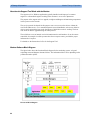
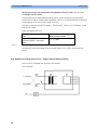
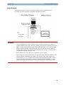
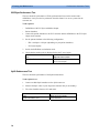
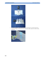
System Example
This illustration shows a system where both the medical electrical equipment and the
non-medical electrical equipment are situated at the patient’s bedside.
WARNING
-
Do not use additional AC mains extension cords or multiple portable socket-outlets. If a
multiple portable socket-outlet is used, the resulting system must be compliant with IEC/EN
60601-1-1. Do not place multiple socket-outlets on the floor. Do not exceed the maximum
permitted load for multiple socket-outlets used with the system. Do not plug additional
multiple socket outlets or extension cords into multiple socket outlets or extension cords
used within the medical electrical system.
-
Do not connect any devices that are not supported as part of a system.
-
Do not use a device in the patient vicinity if it does not comply with IEC/EN 60601-1. The
whole installation, including devices outside of the patient vicinity, must comply with
IEC/EN 60601-1-1. Any non-medical device placed and operated in the patient’s vicinity
must be powered via a separating transformer (compliant with IEC/EN 60601-1-1) that
ensures mechanical fixing of the power cords and covering of any unused power outlets.
63
3 Testing and Maintenance
System Test
System Installation Requirements
64
-
Ensure that the the medical electrical system is installed in a way that the user achieves
optimal use.
-
Make sure the user is informed about the required cleaning, adjustment, sterilization and
disinfection procedures listed in the Instructions for Use.
-
The medical electrical system must be installed in such a way that the user is able to carry
out the necessary cleaning, adjustment, sterilization and disinfection procedures listed in the
Instructions for Use.
-
Ensure that the medical electrical system is installed in a way that an interruption and
restoration of power to any part of the medical electrical system does not result in a safety
hazard.
-
We recommend using fixed mains socket outlets to power the medical system or parts
thereof. Avoid using multiple portable socket-outlets.
-
Any multiple portable socket outlets used must be compliant with IEC 60884-1 and IEC
60601-1-1.
-
Ensure that any part of the system connected to multiple portable socket-outlets is only
removable with a tool, i.e. the multiple portable socket-outlet provides a locking mechanism
to prevent power cords from being plugged or unplugged unintentionally. Otherwise, the
multiple portable socket-outlet must be connected to a separation device. Multiple Socket
Outlets used within the medical electrical system must only be used for powering medical
electrical equipment which is part of the system.
-
Ensure that any functional connections between parts of the medical electrical system are
isolated by a separation device according to IEC 60601-1-1 to limit increased equipment
leakage currents caused by current flow through the signal connections. This only works if
the equipment leakage current of the respective medical electrical system parts is not
exceeded under normal conditions.
-
Avoid increase of equipment leakage currents when non-medical electrical equipment within
the medical electrical system is used. This only works if the equipment leakage current of
the respective medical electrical system parts is not exceeded under normal conditions. Use
additional protective earth connection, separation device or additional non-conductive
enclosures.
-
Within the patient environment it is important to limit electrical potential differences
between different parts of a system. If necessary, use potential equalization equipment
(equipotential cable) or additional protective earth connections.
-
Medical electrical equipment used in medical rooms must be connected to potential
equalization equipment (equipotential cable) to avoid electrical potential differences. Check
your local requirements for details.
System Test
3 Testing and Maintenance
Required Protective Measures at System Installation
For any IT equipment (IEC60950) operated in patient vicinity ensure that the equipment leakage
current does not exceed the limits described in IEC 60601-1. Use a separation device to ensure
compliance. After installation of IT equipment in patient vicinity, an enclosure leakage current
test is required.
65
3 Testing and Maintenance
System Test
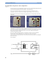
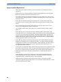
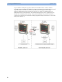
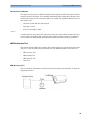
Case 1: Medical Device Combined with Medical Device
If you combine a medical device with another medical device (incl. Philips specified displays) to
form a medical electrical system according to IEC60601-1-1, no additional protective measures
are required. The medical electrical devices may be located in or outside the patient vicinity in a
medically used room. This is valid as long as the medical devices are connected to separate
mains outlets. No system test is required.
66
System Test
3 Testing and Maintenance
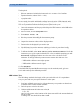
If the combined medical devices are connected to the same multiple portable socket outlet an
enclosure leakage current test of the entire device combination on the multiple portable socket
outlet is required to ensure that the resulting protective earth leakage current and equipment
leakage current does not exceed the limits of IEC 60601-1-1. Avoid using multiple portable
socket outlets. The medical electrical devices may be located in or outside the patient vicinity in
a medically used room. If the limits are exceeded, additional protective measures are required,
e.g. a separation device or the connection of each device to separate mains.
67
3 Testing and Maintenance
System Test
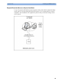
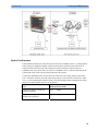
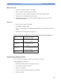
Case 2: Medical Device Combined with a Non-Medical Device
If you combine a medical device with a non-medical device to form a medical electrical system
according to IEC60601-1-1, additional protective measures are required, e.g. usage of a
separation device. The medical electrical devices or the IT equipment may be located in or
outside the patient vicinity in a medically used room. After system installation incl. protective
measures, a system test is required to ensure that the resulting equipment leakage current and
applied part leakage current does not exceed the limits of IEC 60601-1-1.
68
System Test
3 Testing and Maintenance
For any IT equipment (IEC60950) operated in patient vicinity ensure that the equipment leakage
current does not exceed the limits described in IEC 60601-1. Use a separation device to ensure
compliance. After installation of IT equipment in patient vicinity, an enclosure leakage current
test is required.
69
3 Testing and Maintenance
System Test
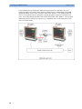
If the combined devices forming the medical electrical system are connected to the same
multiple portable socket outlet, ensure that the resulting protective earth leakage current and
equipment leakage current do not exceed the limits of IEC 60601-1-1. The medical electrical
devices or IT equipment may be located in or outside the patient vicinity in a medically used
room. Avoid using multiple portable socket outlets. If the limits of IEC 60601-1-1 are exceeded,
additional protective measures are required, e.g. a separation device or the connection of each
device to separate mains.
70
System Test
3 Testing and Maintenance
For any IT equipment (IEC60950) operated in patient vicinity ensure that the equipment leakage
current does not exceed the limits described in IEC 60601-1. Use a separation device to ensure
compliance. After installation of IT equipment in patient vicinity, an enclosure leakage current
test is required.
71
3 Testing and Maintenance
System Test
Case 3: Medical Device Combined with a Medical or Non-Medical Device with one Device in a
Non-Medically-Used Room
If you combine a medical device with a medical or non-medical device to form a medical
electrical system according to IEC60601-1-1 using a common protective earth connection and
one of the devices is located in a non-medically used room, additional protective measures are
required, e.g. usage of a separation device or additional protective earth connection. The medical
electrical devices or IT equipment may be located in or outside the patient vicinity. After system
installation incl. protective measures, a system test is required to ensure that the resulting
equipment leakage current does not exceed the limits of IEC 60601-1-1.
72
System Test
3 Testing and Maintenance
73
3 Testing and Maintenance
System Test
If you combine a medical device with a medical or non-medical device to form a medical
electrical system according to IEC60601-1-1 using two separate protective earth connections and
one of the devices is located in a non-medically used room creating a potential voltage
difference, additional protective measures are required, e.g. usage of a separation device or
additional protective earth connection. The medical electrical devices or IT equipment may be
located in or outside the patient vicinity. After system installation incl. protective measures, a
system test is required to ensure that the resulting equipment leakage current does not exceed the
limits of IEC 60601-1-1.
74
System Test
3 Testing and Maintenance
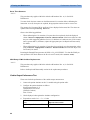
System Test Procedure
If the medical electrical device has already been tested as a standalone device e.g. during factory
safety testing, an equipment leakage current test must only be performed once the device is
connected to the LAN network. If the medical electrical system has not been tested as a
standalone device, the device has to be tested as a standalone device (without connection to the
system) and as part of the system (with connection to the system).
Connect the detachable power cord of the device under test to the safety analyzer's test mains
port. Connect the enclosure test lead of the safety analyzer to the enclosure of the device under
test, e.g. to the equipotential connector. Refer to the documentation that accompanies the safety
analyzer for further details on how to set up the test.
Test
Expected test results
Equipment Leakage Current Test
(Normal Condition)
Sys1 <= 100μA
Equipment Leakage Current Test
(Single Fault Condition)
Sys2 <= 300μA
75
3 Testing and Maintenance
Preventive Maintenance Procedures
After the testing of the device as a standalone device and as part of the system, check that the
resulting values (without connection and with connection to the system) do not differ by more
than +/- 10% from each other.
If the devices in the medical electrical system are connected to a multiple portable socket outlet
the resulting protective earth leakage current needs to be determined. All system components
must be connected to the multiple portable socket outlet and be switched on during this
measurement.
Test
Expected test results
Protective Earth Leakage Current of
Multiple Socket Outlets
Sys3 <= 300μA
Refer to the documentation that accompanies the safety analyzer for further details on how to set
up the test.
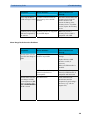
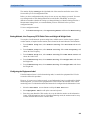
Preventive Maintenance Procedures
Noninvasive Blood Pressure Measurement Calibration
Carry out the noninvasive blood pressure measurement performance tests at least every two
years , or as specified by local laws (whichever comes first).
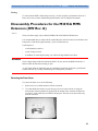
Performance Assurance Tests
Some of the following test procedures must be performed in service mode. To enter service
mode select Operating Modes in the main menu. Then select Service Mode and enter the
password.
If required, open the screen menu in the monitor info line at the top of the screen and select
Service to access the service screen. This is required particularly for Anesthetic Gas Module
testing procedures.
Basic Performance Assurance Test
This section describes the basic performance test procedure. Please refer to the section When to
Perform Tests for detailed information on when which test procedure is required.
Procedure:
Power on the monitoring system and go into demo mode. Check that each connected parameter
(integrated, module, MMS, Gas Analyzer, Vuelink connected device) displays values.
76
Performance Assurance Tests
3 Testing and Maintenance
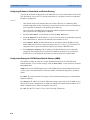
Full Performance Assurance Test
The following sections describe the full performance testing procedures i.e. detailed testing of
each parameter with a patient simulator or specified tools. Please refer to the section When to
perform Tests for information on when which testing procedure is required.
ECG/Resp Performance Test
This test checks the performance of the ECG and respiration measurements.
Tools required: Patient simulator.
ECG Performance
1. Connect the patient simulator to the ECG/Resp connector.
2. Configure the patient simulator as follows:
-
ECG sinus rhythm.
-
HR = 100 bpm or 120 bpm (depending on your patient simulator).
3. Check the displayed ECG wave and HR value against the simulator configuration.
4. The value should be 100bpm or 120 bpm+/- 2 bpm.
Respiration Performance
1. Change the Patient Simulator configuration to:
-
Base impedance line 1500 Ohm.
-
Delta impedance 0.5 Ohm.
-
Respiration rate 40 rpm or 45 rpm.
2. The value should be 40 rpm +/- 2 rpm or 45 rpm +/- 2 rpm.
Test
Expected test results
ECG Performance Test
100bpm +/- 2bpm or
120bpm +/- 2bpm
Respiration Performance Test
40 rpm +/- 2 rpm or
45 rpm +/- 2 rpm
77
3 Testing and Maintenance
Performance Assurance Tests
ECG Sync Performance Test
This test checks the performance of ECG synchronization between the monitor and a
defibrillator. It only needs to be performed when this feature is in use as a protocol at the
customer site.
Tools required:
-
Defibrillator with ECG Sync and Marker Output.
-
Patient simulator.
1. Connect the patient simulator to the ECG connector and the defibrillator to the ECG Sync
Output on the monitor.
2. Set the patient simulator to the following configuration:
-
HR = 100 bpm or 120 bpm (depending on your patient simulator).
-
ECG sinus rhythm.
3. Switch the defibrillator to simulation mode.
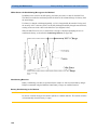
4. Check that the marker pulse is displayed before the T-wave begins.
Test
Expected test results
ECG Sync Performance Test
Marker pulse is displayed before
the T-wave begins
SpO2 Performance Test
This test checks the performance of the SpO2 measurement.
Tools required: none
1. Connect an adult SpO2 transducer to the SpO2 connector.
2. Measure the SpO2 value on your finger (this assumes that you are healthy).
3. The value should be between 95% and 100%.
78
Test
Expected test results
SpO2 Performance Test
95% and 100%
Performance Assurance Tests
3 Testing and Maintenance
Measurement Validation
The SpO2 accuracy has been validated in human studies against arterial blood sample reference
measured with a CO-oximeter. In a controlled desaturation study, healthy adult volunteers with
saturation levels between 70% and 100% SaO2 were studied. The population characteristics for
those studies were:
-
about 50% female and 50% male subjects
-
age range: 18 to 45
-
skin tone: from light to black
NOTE
A functional tester cannot be used to assess the accuracy of a pulse oximeter monitor. However,
it can be used to demonstrate that a particular pulse oximeter monitor reproduces a calibration
curve that has been independently demonstrated to fulfill a particular accuracy specification.
NBP PerformanceTest
This section describes NBP test procedures.The monitor must be in service mode and the screen
“Service A” must be selected to perform these tests. The NBP Performance Test consists of:
-
NBP Accuracy Test
-
NBP Leakage Test
-
NBP Linearity Test
-
Valve Test
NBP Accuracy Test
This test checks the performance of the non-invasive blood pressure measurement. Connect the
equipment as shown:
79
3 Testing and Maintenance
Performance Assurance Tests
Tools required:
-
Reference manometer (includes hand pump and valve), accuracy 0.2% of reading.
-
Expansion chamber (volume 250 ml +/- 10%)
-
Appropriate tubing.
In service mode, the systolic and diastolic readings indicate the noise of NBP channels 1 and 2
respectively. When static pressure is applied, the reading in NBP channel 1 should be below 50.
The value in parentheses indicates the actual pressure applied to the system.
1. Connect the manometer and the pump with tubing to the NBP connector on the MMS and to
the expansion chamber.
2. In service mode, select the Setup NBP menu.
3. Select Close Valves: On
4. Raise the pressure to 280 mmHg with the manometer pump.
5. Wait 10 seconds for the measurement to stabilize.
6. Compare the manometer values with the displayed values.
7. Document the value displayed by the monitor (x1).
8. If the difference between the manometer and displayed values is greater than 3 mmHg,
calibrate the MMS. If not, proceed to the leakage test.
9. To calibrate the MMS, select Close Valves off then Calibrate NBP and wait for the
instrument to pump up the expansion chamber.Wait a few seconds after pumping stops until
EnterPrVal is highlighted and then move the cursor to the value shown on the
manometer. If one of the following prompt messages appears during this step, check
whether there is leakage in the setup:
-
NBP unable to calibrate–cannot adjust pressure
-
NBP unable to calibrate–unstable signal
10. Press Confirm.
If the INOP NBP Equipment Malfunction message occurs in monitoring mode, go back to
service mode and repeat the calibration procedure.
NBP Leakage Test
The NBP leakage test checks the integrity of the system and of the valve. It is required once
every two years and when you repair the monitor or replace parts.
1. If you have calibrated, repeat steps 2 to 6 from the accuracy test procedure so that you have
280 mmHg pressure on the expansion chamber.
2. Watch the pressure value for 60 seconds.
3. Calculate and document the leakage test value (x2).
x2 = P1 - P2
where P1 is the pressure at the beginning of the leakage test and P2 is the pressure displayed
after 60 seconds.
The leakage test value should be less than 6 mmHg.
80
Performance Assurance Tests
3 Testing and Maintenance
NBP Linearity Test
1. Reduce the manometer pressure to 150 mmHg.
2. Wait 10 seconds for the measurement to stabilize.
3. After these 10 seconds, compare the manometer value with the displayed value.
4. Document the value displayed by the monitor (x3)
5. If the difference is greater than 3 mmHg, calibrate the MMS (see steps 9 to 10 in the
accuracy test procedure).
Valve Test
1. Raise the pressure again to 280 mmHg.
2. Select Close valves: Off.
3. Wait five seconds and then document the value displayed. The value should be less than 10
mmHg.
4. Document the value displayed by the monitor (x4).
Expected Test Results for NBP Accuracy Test, Leakage Test, Linearity Test & Valve Test
Test
Expected test results
Accuracy test
x1 = value displayed by monitor
Difference ≤ 3mmHg
Leakage test
x2 = leakage test value
x2 < 6 mmHg
Linearity test
x3 = value displayed by monitor
Difference ≤ 3mmHg
Valve Test
x4 = value < 10 mmHg
Invasive Pressure Performance Test
This test checks the performance of the invasive pressure measurement.
Tools required: Patient simulator.
1. Connect the patient simulator to the pressure connector.
2. Set the patient simulator to 0 pressure.
3. Make a zero calibration.
4. Configure the patient simulator as P(static) = 200 mmHg.
5. Wait for the display.
81
3 Testing and Maintenance
Performance Assurance Tests
6. The value should be 200 mmHg ± 5 mmHg. If the value is outside these tolerances, calibrate
the Invasive Pressure measurement. If the measurement was calibrated with a dedicated
reusable catheter, check the calibration together with this catheter.
Table 4:
Test
Expected test results
Invasive Pressure Performance Test
200 mmHg ± 5 mmHg
Temperature Performance Test
This test checks the performance of the temperature measurement.
Tools required: Patient simulator (with 0.1°C or 0.2°F).
1. Connect the patient simulator to the temperature connector.
2. Configure the patient simulator to 40°C or 100°F.
3. The value should be 40°C ± 0.2°C or 100°F ± 0.4°F.
Table 2:
Test
Expected test results
Temperature Performance Test
40°C ± 0.2°C or 100°F ± 0.4°F
M3014A Capnography Extension Performance Tests
The procedures below describe the mainstream and sidestream CO2 performance tests for the
M3014A Capnography Extension.
Mainstream CO2 Accuracy Check
Tools Required:
-
three airway adapters
-
Verification Gas M2506A
-
Gas cylinder regulator M2505A
You also need a local barometric pressure rating received from a reliable local source (airport,
regional weather station or hospital weather station) which is located at the same altitude as the
hospital.
Procedure:
1. Attach the M2501A CO2 sensor to the patient monitor. Attach an airway adapter to the
sensor. Make sure that the sensor is disconnected from the patient circuit.
2. Switch on the patient monitor.
3. Enter the monitor’s Service Mode.
82
Performance Assurance Tests
3 Testing and Maintenance
4. Using the sensor status provided in the M2501A Serial protocol, wait for the M2501A
sensor to warm up to its operating temperature.
5. The default setting for gas temperature is 22°C. If the gas temperature is significantly above
or below this value, correct the gas temperature setting.
6. Zero the sensor on the airway adapter being used in this test. Ensure Zero Gas is set to Room
Air
7. Attach a regulated flowing gas mixture of 5% CO2, balance N2 to the airway adapter.
8. Set the gas correction to off.
9. Allow a few seconds for the gas mixture to stabilize and observe the CO2 value. The
expected value is 5% of the ambient pressure ±2mmHg
NOTE
Make sure that you follow the above steps correctly. If the sensor fails this check it must be
exchanged. The sensor cannot be calibrated.
Example for an expected test result:
The expected test result for an altitude of 0 m (sea level) at approximately 760 mmHg ambient
pressure is:
Table 6:
Test
Expected test results (x1)
Acceptance Range
Mainstream CO2 Accuracy
Test
5% of 760 mmHg pressure ±2mmHg
36 mmHg 40 mmHg
NOTE
The expected test results will differ depending on the conditions (i.e. altitude or ambient
pressure).
Sidestream CO2 Accuracy Check
Tools Required:
-
Cal gas flow regulator M2267A
-
Cal tube 13907A
-
Verification Gas M2506A
-
Straight Sample Line M2776A
You also need a local barometric pressure rating received from a reliable local source (airport,
regional weather station or hospital weather station) which is located at the same altitude as the
hospital.
Procedure:
1. Attach the M2741A CO2 sensor to the patient monitor. Attach the sample line and the cal
tube to the sensor. Make sure that the sensor is disconnected from the patient circuit.
2. Switch on the patient monitor.
3. Enter the monitor’s Service Mode.
83
3 Testing and Maintenance
Performance Assurance Tests
4. Using the sensor status provided in the M2741A Serial protocol, wait for the M2741A
sensor to warm up to its operating temperature.
5. Zero the sensor. Ensure Zero Gas is set to Room Air
6. Attach a regulated flowing gas mixture of 5% CO2, balance N2 to the cal tube.
7. Set the gas correction to off.
8. Allow a few seconds for the gas mixture to stabilize and observe the CO2 value. The
expected value is 5% of the ambient pressure ±2mmHg
NOTE
Make sure that you follow the above steps correctly. If the sensor fails this check it must be
exchanged. The sensor cannot be calibrated
Example for an expected test result:
The expected test result for an altitude of 0 m (sea level) at approximately 760 mmHg ambient
pressure is:
Test
Expected test results (x2)
Acceptance Range
Sidestream CO2 Accuracy
Test
5% of 760 mmHg pressure ±2mmHg
36 mmHg 40 mmHg
NOTE
The expected test results will differ depending on the conditions (i.e. altitude or ambient
pressure).
Sidestream CO2 Flow Check
Check the flow rate in the Sidestream CO2 extension as follows:
1. Connect the flowmeter to the sample line
2. Check on the flowmeter the flow that the Sidestream CO2 extension pump draws. It should
be 50 ml/min ± 10 ml/min. If the value is not within tolerance check your setup again and
perform another flow check. If it fails again, the sensor must be replaced. The sensor cannot
be calibrated.
84
Performance Assurance Tests
3 Testing and Maintenance
Microstream CO2 Performance Test
Allow five seconds between individual service procedures to ensure stable equipment conditions.
When certain monitor procedures are running, service procedures are not possible and trying to
start them will result in a message Service Operation Failed in the monitor’s status line.
Wait until the monitor completes the current operation, then restart the service procedure.
This test checks the performance of the Microstream CO2 measurement. The Microstream CO2
measurement can either be integrated into the IntelliVue MP5 monitor or, for other IntelliVue
monitors, into the M3015A MMS Extension. The Microstream CO2 performance test is required
once per year and when the instrument is repaired or when parts are replaced.
This test uses calibration equipment that you can order (see the Parts section for the part
number). The procedure is summarized in the following steps. Refer to the documentation
accompanying the equipment for detailed instructions.
Tools Required:
-
Standard tools, such as screwdriver, tweezers
-
Electronic flowmeter, M1026-60144
-
Gas calibration equipment:
-
Cal 1 gas 15210-64010 (5% CO2)
-
Cal 2 gas 15210-64020 (10% CO2)
-
Cal gas flow regulator M2267A
-
Cal tube 13907A
-
Calibration Line M3015-47301
You also need a local barometric pressure rating received from a reliable local source (airport,
regional weather station or hospital weather station) which is located at the same altitude as the
hospital.
The CO2 calibration for the Microstream extension consists of the following steps:
-
Leakage check
-
Barometric pressure check and calibration, if required.
-
Pump check
-
Flow check and calibration, if required
-
Noise check
-
CO2 Cal check and calibration, if required
-
CO2 Cal verification using 2nd cal gas
Perform all checks in the same session.
85
3 Testing and Maintenance
Performance Assurance Tests
Leakage Check
The leakage check consists of checking the tubing between:
-
the pump outlet and the mCO2 outlet and
-
the pump inlet and FilterLine inlet.
Check the user’s guide of the flowmeter for details on how to make a correct flow reading.
Part 1
1. Go into service mode and select Setup CO2 menu.
2. Connect a FilterLine to the Microstream CO2 input to start the pump running.
3. Check the ambient pressure and the cell pressure shown in the monitor’s status line. The cell
pressure should be approximately 20 mmHg lower than ambient pressure.
4. Connect the flowmeter outlet to the FilterLine inlet using a flexible connecting tube.
5. Block the mCO2 outlet using your fingertip and observe the flowmeter display. The value on
the flowmeter (x1) should decrease to between 0 and 4 ml/min, accompanied by an audible
increase in pump noise. If the value is within the tolerance limits, continue with part 2 of the
leakage check.
6. If the value is outside the tolerance limits, there is a leakage between the pump outlet and the
mCO2 outlet.
7. Open the MMS Extension or MP5 and check the tubing connections at the pump outlet and
the extension gas outlet. If the connections are good, then there is a leakage in the tubing and
you must exchange the MMS Extension or the mCO2 Assembly of the MP5 respectively.
Part 2
1. Disconnect the flowmeter from the Part 1 setup and connect the flowmeter inlet to the
M3015A gas outlet or the MP5 mCO2 gas outlet.
2. Leave the Filterline connected to the M3015A inlet or the MP5 mCO2 inlet..
3. Block the inlet of the FilterLine using your fingertip and observe the flowmeter display. The
value on the flowmeter (x2) should decrease to between 0 and 4 ml/min, accompanied by an
audible increase in pump noise. The cell pressure shown in the status line on the display
should decrease to between 300 and 500 mmHg. Do not block the inlet for longer than 25
seconds as this will lead to an “Occlusion” INOP. If the value is within the tolerance limits,
there are no leakages and the leakage check is completed; proceed to the pump check.
4. If the value is not within the tolerance limits, there is a leakage between the FilterLine inlet
and the pump inlet.
5. Check the FilterLine connections and open the M3015A or MP5 to check the tubing
connections at the pump inlet and the M3015A or MP5 mCO2 gas inlet. If the connections
are good, try replacing the FilterLine and repeating the leakage check. If the situation
remains, there is a leakage in the tubing and the M3015A or the mCO2 assembly of the MP5
must be exchanged.
86
Performance Assurance Tests
3 Testing and Maintenance
Barometric Pressure Check and Calibration
Check the barometric pressure value in the M3015A MMS Extension or the MP5 as follows:
1. Go into service mode and select Setup CO2 menu.
2. Connect a FilterLine to the Microstream CO2 input. This activates the pump in the M3015A
MMS Extension or the MP5.
3. The status line at the bottom of the screen displays “CO2 pressure reading (ambient/cell)
xxx/yyy” where xxx is the ambient pressure and yyy is the measured cell pressure. Check
whether the ambient pressure value (x3) matches (within the acceptable tolerance of ±12mm
Hg) the reference value you have received. If so, proceed to the leakage check. If the value
is not correct, calibrate as follows.
a. Select CO2 then select Barom.Press to activate a table of values.
b. Select the value in the table which matches the reference value received from a reliable local
source (airport, regional weather station or hospital weather station). (The values are
displayed with a resolution of 2 mmHg up to 500 mmHg and a resolution of 1 mmHg from
500 mmHg to 825 mmHg.) Note: the selected value must be within ±10% of the current
measured ambient pressure, otherwise an error message will occur at restarting the monitor.
c. Confirm the barometric pressure setting.
d. Check that the ambient pressure displayed in the status line at the bottom of the screen is the
same as the value which you selected from the list in step b.
Pump Check
1. Connect the flowmeter inlet to the mCO2 gas outlet.
2. Connect the FilterLine to the mCO2 inlet.
3. Block the inlet of the FilterLine using your fingertip and observe the cell pressure on the
monitor display. The cell pressure (x4) should be more than 120 mmHg below the ambient
pressure shown. If the pressure difference is less than 120 mmHg, the pump is not strong
enough and you should replace it, irrespective of the Pump OpTime.
Flow Rate Check and Calibration
Check the flow rate in the M3015A MMS Extension or the MP5 as follows:
1. Connect the flowmeter to the CO2 FilterLine.
2. Check on the flowmeter the flow that the M3015A MMS Extension or MP5 mCO2 pump
draws (x5). It should be 50 ml/min ± 7.5 ml/min. If the value is within tolerance, proceed to
the CO2 Gas calibration check. If the value is not within tolerance, calibrate as follows.
3. Adjust the flow in the instrument by selecting Increase Flow or Decrease Flow until
it is as close as possible to 50 ml per minute as indicated on the flowmeter gauge.
4. When you are satisfied that the flow is set as close as possible to 50 ml per minute, select
Store Flow and confirm the setting. If you do not store the adjusted flow within 60
seconds of the adjustment, the old flow setting is restored.
87
3 Testing and Maintenance
Performance Assurance Tests
5. If you cannot adjust the flow to within tolerance, replace the pump . If you still cannot make
the flow adjustment, this indicates a fault in the measurement extension, which must be
replaced.
Note that the pump can only be replaced on M3015A with the old hardware Rev. A (i.e.
Serial No. DE020xxxxx
Noise Check
1. With the monitor in service mode, select Setup CO2 menu.
2. Disconnect the flowmeter and connect the 5% calibration gas and flow regulator in its place.
3. Open the valve to apply the 5% calibration gas and wait until the value is stable.
4. Check the noise index (x6) displayed next to the CO2 value on the display (this indicates the
level of noise on the CO2 wave). If the value exceeds 3 mmHg, replace the measurement
extension.
CO2 Gas Measurement Calibration Check
After switching the measurement extension on, wait at least 20 minutes before checking the
calibration. Check the calibration of the CO2 gas measurement as follows:
1. Check that the 5% calibration gas and flow regulator are connected.
2. Calculate the expected measurement value in mmHg as follows:
0.05 x (ambient pressure) = value mmHg
for example 0.05 x 736 = 36.8 mmHg (with an ambient pressure of 736 mmHg)
3. Open the valve on the flow regulator to allow 5% CO2 gas to flow into the extension. Allow
the value to stabilize.
4. Check that the value on the instrument (measurement value on the main screen, x7) matches
the calculated mmHg value ± 2.6 mmHg. If the value is outside the tolerance, calibrate as
described in step in this procedure onwards.
5. Disconnect the 5% calibration gas and connect the 10% calibration gas.
6. Calculate the expected measurement value and tolerance in mmHg as follows:
0.1 x (ambient pressure) = value mmHg
±0.07 x (value mmHg) = tolerance
for example 0.1 x 737 mmHg = 73.7 mmHg (with an ambient pressure of 737 mmHg)
±0.07 x 73.7 mmHg = ±5.16 mmHg tolerance
7. Open the valve on the flow regulator to allow 10% CO2 gas to flow into the extension.
Allow the value to stabilize.
8. Check that the value on the instrument (x8) matches the calculated mmHg value within the
calculated tolerance. If so, the measurement extension is correctly calibrated. If the value is
outside the tolerance, calibrate as follows.
9. If not already connected, connect the 5% calibration gas.
10. Select Cal. CO2.
11. Select the value for the calibration gas. (The default value is 5.0%.)
88
Performance Assurance Tests
3 Testing and Maintenance
12. Open the valve on the calibration gas to allow CO2 gas to flow into the extension. Allow the
value to stabilize before the start of the calibration. Leave the valve open until the instrument
gives a prompt that gas can be removed.
13. The extension calibrates and prompts when calibration is successful.
Calibration Verification
1. Reopen the 5% gas valve and allow the value to stabilize.
2. Check that the value displayed on the monitor is correct within the tolerance (see step
above).
3. Disconnect the 5% calibration gas and connect the 10% calibration gas.
4. Open the valve on the flow regulator to allow 10% CO2 gas to flow into the extension.
Allow the value to stabilize.
5. Check that the value displayed on the monitor is correct within the tolerance (see step
above).
If one or both values are not within tolerances, you must exchange the M3015A MMS Extension
or the MP5 mCO2 Assembly.
Test
Expected Test Results
Leakage Check
parts 1 and 2
x1 = value of part 1 leakage check on flowmeter
(x1< 4.0 ml/min)
x2 = value of part 2 leakage check on flowmeter
(x2< 4.0 ml/min)
Barometric
Pressure Check
x3 = difference between the reference pressure and the
measured ambient pressure displayed on the monitor
(x3<12 mmHg)
Pump Check
x4 = difference in pressure between cell pressure and
ambient pressure displayed on the monitor during
occlusion (x4 >120 mmHg)
Flow Check
x5 = difference between measured value and 50.0
ml/min (x5<7.5 ml/min)
Noise Check
x6 = noise index displayed on monitor (x6<3.0)
CO2 Gas
Calibration Check
x7 = difference between measured CO2 value and
calculated value, based on 5% CO2 cal. gas. (x7 < 2.6
mmHg)
CO2 Cal
Verification
x8 = difference between measured CO2 value and
calculated value, based on 10% CO2 cal. gas.
(x8 < ± {0.07 x value calculated})
89
3 Testing and Maintenance
Performance Assurance Tests
Reset Time Counters
NOTE
This procedure only applies to M3015A with the old hardware Rev. A (i.e. Serial No.
DE020xxxxx
You must check the time counters on the Microstream CO2 extension before calibrating the
instrument. As well, when parts are replaced, the appropriate counters must be reset to zero.
The counters for CO2 pump, IR Src and Last Cal are displayed in the status line. The values are
updated when entering the Setup CO2 menu.
Observe the following guidelines:
-
When calibrating the CO2 extension, if no parts have been replaced, check the displayed
values of Reset PumpOpTime and Reset IRSourceTime selections to make sure that
they are within suggested guidelines for use (15, 000 hours of continuous use). If the counter
time is greater than 15, 000 hours, replace the appropriate part. See Repair and Disassembly
for details.
-
When calibrating the CO2 extension, if parts have been replaced, reset the appropriate values
using the Reset PumpOpTime and Reset IRSourceTime selections. See Repair and
Disassembly for details.
Resetting the PumpOpTime generates the INOP: “CO2 OCCLUSION”. To clear this INOP you
must perform a flow check and store the flow in service mode (select Store Flow).
CO2 Pump / CO2 Scrubber Replacement
NOTE
This procedure only applies to M3015A with the old hardware Rev. A (i.e. Serial No.
DE020xxxxx
Refer to the Repair and Disassembly section for the replacement procedures.
Cardiac Output Performance Test
These tests check the performance of the cardiac output measurement.
1. Connect the patient simulator to the C.O. module using the patient cable.
2. Configure the patient simulator as follows:
Injection temperature: 2 °C
Computation Const: 0.542
(Edward's Catheter)
Flow: 5 l/min
3. Check displayed value against the simulator configuration.
4. Expected test result: C.O. = 5 +/– 1 l/min.
90
Test
Expected test results
Cardiac Output Performance Test
C.O. = 5 +/– 1 l/min
Performance Assurance Tests
3 Testing and Maintenance
Service Tool Procedure, Version 1
This procedure applies for Service Tool M1012-61601 in combination with C.O. modules
without option C10 and M3012A MMS extensions with option C05.
1. In monitoring mode, connect the C.O. interface cable to the module.
2. Connect one side of the service tool to the injectate receptacle of C.O. interface cable and
the other side to catheter cable receptacle.
3. Enter the C.O. Procedure window and check the results. The expected test result is:
Tblood = 37.0oC +/- 0.1oC
Test
Expected test results
Cardiac Output Service Tool
Procedure Version 1
Tblood = 37.0oC +/- 0.1oC
Service Tool Procedure, Version 2
This procedure applies only for Service Tool M1012-61601 in combination with C.O. modules
with option C10 and for the M3012A MMS Extension with option C10.
1. In monitoring mode, connect the C.O. interface cable to the module.
2. Connect one side of the service tool to the injectate receptacle of the C.O. interface cable
and the other side to the catheter cable receptacle.
3. Enter C.O. Procedure window and check results for:
-
Method of measurement
-
Arterial Catheter constant
-
Tblood
The expected results are:
-
Transpulmonary
-
341
-
Tblood = 37.0oC +/- 0.1oC
4. Make sure the main alarms are switched on.
5. Disconnect the Catheter cable receptacle from the service tool
6. Enter the Setup C.O Window and change the method of measurement to “Right Heart”
7. Enter the C.O. Procedure window and check the Tinj value. The expected result is:
Tinj = 0.0oC +/- 0.1oC
Test
Expected test results
Cardiac Output Service Tool
Procedure Version 2
Tinj = 0.0oC +/- 0.1oC
91
3 Testing and Maintenance
Performance Assurance Tests
Power Loss Alarm Buzzer Performance Test (only if Multi-Port Nurse Call Connector Board
is installed)
1. Switch on the monitor.
2. Remove the battery and disconnect the monitor from AC power.
3. The Power Loss Alarm Buzzer should beep for about one minute.
4. To switch off the alarm sound, either press the power button, connect the monitor to AC
power or insert a battery
Test
Expected test results
Power Loss Alarm Buzzer
Performance Test
Beep for one minute
IntelliVue 802.11 Bedside Adapter Communication Test
1. Make sure the LAN cable is disconnected from the rear of the monitor, then switch on the
monitor.
2. Go into Service Mode and select Main Setup -> Network -> Setup WLAN. In the
Setup WLAN menu:
-
set Mode to either 802.11Ah, 802.11G, 802.11Bg (not recommended), Auto (not
recommended) or None (this setting disables the wireless LAN functionality
permanently), to match your wireless infrastructure installation.
-
set SSID to match your installation.
-
set the Country code to “1000”. Setting the country code to this value will
automatically adjust the regulatory domain to match the configuration of the
infrastructure. Do not set the country code to values other than “1000” unless otherwise
instructed.
-
set the Security Mode to WPA(PSK) and enter the WPA password (string between
8 and 63 characters).
3. Select Main Setup -> WLAN Diagnostic to access the service window.
4. Proper installation of the IntelliVue 802.11 Bedside Adapter is assured by connecting to an
access point over the wireless link. Place the monitor with the IntelliVue 802.11 Bedside
Adapter installed in close proximity to the access point (e.g. if the access point is mounted
on the ceiling, place the monitor directly below). Wait until the Conn.Status field in the
service window shows Authenticatd (for Rel. C.0 monitors)or Connected (for Rel D.0 or
higher). Take the monitor approximately 5 m away from the access point. There should be
no walls or other obstacles between the monitor and the access point. The following should
apply:
92
Performance Assurance Tests
-
3 Testing and Maintenance
Observe the RSSI (Received Signal Strength Indicator) value for at least 5 - 10 seconds.
The RSSI value wil fluctuate but should stay above 30 in a 5 m distance from the access
point used. The wireless link should be active, i.e. the Conn.Status field should be
Authenticatd (for Rel. C.0 monitors)or Connected (for Rel D.0 or higher), and the other
fields should contain values. If the RSSI value is significantly lower, check the distance
to the access point and the antenna orientation at the monitor. The antenna orientation
should be vertical, but the physical placement of the monitor or other equipment within
its vicinity as well as walls or other obstacles may influence the antenna orientation
required to receive the best RSSI value.
5. If this test fails, retry in a different physical area with a different access point.
6. Perform the Wireless Switch test blocks as described in the Philips IntelliVue 802.11 a/g
Infrastructure Installation and Configuration Guide.
Test
Expected test results
IntelliVue 802.11 Bedside Adapter
Performance Test
RSSI value above 30
IIT Communication Test
1. Make sure the LAN cable is disconnected from the rear of the monitor, then switch on the
monitor.
2. Go into Configuration mode and, in the Network menu, set the RF Access Code in each
profile to match your installation.
3. Go into Service Mode. Select Main Setup -> Instr. Telemetry to access the
Instrument Telemetry Service window.
4. Proper installation of the IIT module is assured by connecting to an access point over the
wireless link. Place the monitor with the IIT module installed in close proximity to the
access point (e.g. if the access point is mounted on the ceiling, place the monitor directly
below). Wait until the Conn.Status field in the Instrument Telemetry Service window
shows Active. Take the monitor approximately 5 m away from the access point. There should
be no walls or other obstacles between the monitor and the access point. The following
should apply:
-
Observe the RSSI (Received Signal Strength Indicator) value for at least 5 - 10 seconds.
The RSSI value should be around -50 ±10 in a 5 m distance from the access point used
and the IIT link should be active, i.e. the Conn.Status field should be Active and the
other fields should contain values. If the RSSI value is significantly lower, check the
distance to the access point and the antenna orientation at both the monitor and the
access point (both should be vertical).
-
Remove the antenna. The RSSI value should be around -90 ±10. The IIT link may be
active but the connection could be unreliable. The Conn. Status field may toggle
between Inactive and Seeking. If the difference between the RSSI values measured with
and without antenna is significantly lower, check the antenna and the antenna connector
for damage and verify that the cable fom the IIT adapter to the antenna connector plate
is connected properly.
5. If this test fails, retry in a different physical area with a different access point.
93
3 Testing and Maintenance
Performance Assurance Tests
Error Conditions:
-
The field MAC Instr. Tele should show a value unequal to 0000 0000 0000. If it
does not, there is a communication problem between the monitor and the IIT adapter.
-
With an incorrect RF Access Code or an incorrect or defective antenna installation, the
fields IP Address,Server IP, Subnet Mask, and RSSI in the Instrument
Telemetry Service window will stay blank. The field Conn. Status will slowly toggle
between Inactive and Seeking.
6. Perform the Access Point Controller (APC) test blocks as described in the Philips IntelliVue
Wireless Network Installation and Configuration Guide.
Short Range Radio (SRR) Performance Test
1. Make sure that the short range radio interface is configured as follows: SRR On and
appropriate channel selected.
2. Assign a telemetry transceiver to the IntelliVue Monitor according to the procedure
described in the Instructions for Use of the patient monitor.
3. Check that the following conditions are fulfilled:
a. Place the telemetry transceiver close to the monitor.
b. The telemetry transceiver status is displayed on the monitor in the measurement
selection window.
c. Waves or numerics from the telemetry transceiver are displayed on the monitor. There a
re no dropouts or gaps in waves or numeric transmission.
d. The battery status of the telemetry transceiver is displayed in the measurement selection
window.
e. The Signal Quality Indicator shows at least
4. Check that the data from the telemetry transceiver is transmitted to the monitor within a 1m
radius and that there are no dropouts or gaps in waves or numerics.
5. Check whether the connection remains stable within a 5m radius from the monitor.
6. Switch on all telemetry transceivers used on the site and check that there are no interferences
between the transceivers and their assigned monitors.
7. Check and record the coverage area of the telemetry transceivers and inform the customer
about this coverage area.
94
Reporting of Test Results
3 Testing and Maintenance
Reporting of Test Results
Philips recommends all test results are documented in accordance with local laws. Authorized
Philips personnel report test result back to Philips to add to the product development database.
While hospital personnel (biomedical engineers or technicians) do not need to report results to
Philips, Philips recommends that they record and store the test results in accordance with local
laws.
The following table lists what to record after completing the tests in this chapter. Record the
results in the empty column in Table 16.
The following is a guide as to what your documentation should include:
-
Identification of the testing body (for example, which company or department carried out the
tests).
-
Name of the person(s) who performed the tests and the concluding evaluation.
-
Identification of the device(s) and accessories being tested (serial number, etc.).
-
The actual tests (incl. visual inspections, performance tests, safety and system tests) and
measurements required
-
Date of testing and of the concluding evaluation.
-
A record of the actual values of the test results, and whether these values passed or failed the
tests.
-
Date and confirmation of the person who performed the tests and evaluation.
The device under test should be marked according to the test result: passed or failed.
Carrying Out and Reporting Tests
Test Report
Testing Organization:
Name of testing person:
Test before putting into service (reference value)
Recurrent Test
Test after Repair
Responsible Organization:
Device Under Test:
ID-Number
Product Number:
Serial No.:
Accessories:
Measurement Equipment (Manufacturer, Type,
Serial No.):
Functional Test (parameters tested):
95
3 Testing and Maintenance
Reporting of Test Results
Test and Inspection Matrix
Expected Test Results
Record the Results (mandatory for
Philips Personnel only)
What to record
Actual
Results
Perform Visual
Inspection
Pass or Fail
V:P or V:F
Power On
Power on the
unit. Does the
self-test complete
successfully
If Yes, Power On test is
passed
PO:P or PO:F
Noninvasive
Blood
Pressure
Performance
Tests
Perform the
Accuracy Test
X1 = value displayed by
monitor
PN:P/X1 or
Test Block
Test or
Inspection to be
Performed
Visual
Inspection
PN:F/X1
Difference <= 3mmHg
Performance
Leakage Test
X2 = leakage test value
PN:P/X2 or
X2 < 6 mmHg
PN:F/X2
Performance
Linearity Test
X3 = value displayed by
monitor
PN:P/X3 or
PN:F/X3
Difference <= 3mmHg
Performance
Valve Test
X4 = value < 10 mmHg
Temperature
Performance
Test
Perform the
Temperature
Performance Test
X1= 40°C ± 0.2°C or 100°F ±
0.4°F
PT: P/X1 or
All other
performance
tests
Perform the
remaining
parameter
performance
tests, if applicable
See expected results in test
procedures
P: P or
Safety (4)
Perform Safety
Test (4): Patient
Leakage Current
- Single Fault
Condition, mains
on applied part.
Maximum leakage current
(X1): <=50 μA
S(4): P/X1 or
Perform the
system test
according to
subclause 19.201
of IEC/EN
60601-1-1, if
applicable, after
forming a system
Equipment Leakage Current:
Sys: PSys1/PSys2
Sys1 <= 100 μA (Normal
Condition)
or
System
(Sys 1-2)
96
PN:P/X4 or
PN:F/X4
Sys2 <= 300μA (Single Fault
Condition
PT: F/X1
P: F
S(4): F/X1
Sys: FSys1/Fsys2
Reporting of Test Results
Test Block
System
(Sys 3)
Test or
Inspection to be
Performed
Perform the
system test
according to
subclause 19.201
of IEC/EN
60601-1-1, if
applicable, after
forming a system
3 Testing and Maintenance
Expected Test Results
Protective Earth Leakage
Current if medical electrical
system components are
connected to the same
Multiple Portable Socket
Outlet:
Record the Results (mandatory for
Philips Personnel only)
What to record
Actual
Results
Sys: PSys3
or
Sys: FSys3
Sys3 <= 300 μA
Key: P = Pass, F = Fail, X or Sys = test value to be recorded
NOTE
All values for current and voltage are the root mean square (r.m.s.) values, unless otherwise
stated.
Evaluation:
Yes
No
Safety and Functional Test passed
Repair required at a later date, safety and functional test passed
Device must be taken out of operation until repair and passed tests
Device failed and must be taken out of operation.
Notes:
Next Recurrent Test:
Name:____________________________________________________
Date/Signature:_____________________________________________
Evaluation of Test Results
The evaluation of the test results must be performed by appropriately trained personnel with
sufficient product, safety testing and application knowledge.
If any test results are between 90% and 100% of the respective expected result, the previously
measured reference values must be taken into consideration for the assessment of the electrical
safety of the device under test. If no reference values are available, you should consider shorter
intervals between upcoming recurrent tests.
NOTE
If any single test fails, testing must be discontinued immediately and the device under test must
be repaired or labeled as defective. Be sure to inform the user about the test failure in writing.
97
3 Testing and Maintenance
Other Regular Tests
Other Regular Tests
The care and cleaning requirements that apply to the monitor and its accessories are described in
the Instructions for Use. This section details periodic maintenance procedures recommended for
the monitor and its accessories.
Locking/Unlocking Touch Operation
To temporarily disable touchscreen operation of the monitor, press and hold the Main Screen
key. The message “Touch disabled, press Main Screen” will appear on the screen. Press and hold
the Main Screen key again to re-enable touchscreen operation.
Battery Handling, Maintenance and Good Practices
This section provides some information on how to handle and maintain the battery in order to get
the best usage from it. Additionally, some good working practices are also given regarding the
correct disposal of the battery.
NOTE
If your MP2/X2 is connected to an IntelliVue Information Center, you should make sure that the
IIC uses the text catalog revision F.0 or later, otherwise battery INOPs may not display correctly
on the IIC. Consult your IIC documentation for instructions on upgrading the text catalog.
About the Battery
When monitoring a patient, one Philips M4607A rechargeable Lithium Ion battery must always
be inserted into the battery compartment on the right side of the MP2/X2. This applies even
when you are running the MP2/X2 external power, either via the external power supply or when
connected to a host monitor. The battery has the effect of sealing the battery compartment,
thereby preventing the ingress of fluids or foreign bodies. A severe yellow INOP (!!INSERT
BATTERY) will be issued if the monitor is connected to AC mains without a battery fully
inserted in the battery compartment. This INOP will persist until a battery is loaded.
98
Battery Handling, Maintenance and Good Practices
3 Testing and Maintenance
To use the MP2/X2 with battery power, disconnect it from the host monitor or the external
power supply (M8023A).
The rechargeable Lithium-Ion Mangan battery used in the MP2/X2 is regarded as a Smart
battery because it has built-in circuitry. (This circuitry communicates battery-status information
to the Monitor.)
To get the most out of the battery, observe the following guidelines:
-
Condition the battery only upon maintenance request prompt on display.
-
If a battery shows damage or signs of leakage, replace it immediately. Do not use a
faulty battery in the MP2/X2.
-
Capabilities of integrated battery charger: 10.8 V, 1 mAh (typ.)
Actual current / voltage: depends on smart battery request and monitor configuration
The approximate charging time is 2 hours with the monitor switched off and up to 12 hours
or more during monitor operation, depending on the monitor configuration.
Checking the Battery Status
When the MP2/X2 is connected to the external power supply (M8023A), the battery charges
automatically. The battery can be charged remotely from the MP2/X2 by using the battery
charger. Use only the M8043A Smart battery charger with the additional adapter.
Battery status (level of charge) is indicated in several ways:
-
LED on the front panel of the Monitor.
-
Battery gauge.
-
Display of battery time below gauge.
-
Battery status window.
-
INOP messages.
The AC Power LED is only on when the power cord is connected and AC power is available to
the Monitor. In this case, the battery can be either charging or fully charged.
The battery LED can be yellow, or red depending on the following conditions:
Battery LED Colors
Yellow
If the MP2/X2 is connected
to a host monitor or
external power supply , this
means
battery charging
≤ 10 minutes power remaining
Red, flashing
Red, flashes
intermittently
1
2
If the monitor is running on
battery power, this means
battery or charger
malfunction1,2
battery or charger
malfunction1,2
indicated by malfunction symbol and INOP
for further details see Troubleshooting section
99
3 Testing and Maintenance
Battery Handling, Maintenance and Good Practices
Battery Status on the Main Screen
Battery status information can be configured to display permanently on all Screens. It shows the
status of the battery, with the battery power remaining and, when the battery is not charging, an
estimate of the monitoring time this represents.
Battery power gauge:
This shows the remaining battery power. It is divided into sections, each representing 20% of the
total power. If three sections are filled, as in this example, this indicates that 60% battery power
remains. If no battery is detected, a blank battery gauge marked with a flashing red X is
displayed. If no data is available from the battery, a question mark is shown in the gauge.
Battery status/malfunction indicator:
Normal battery function is indicated by the battery power gauge, together with the remaining
operating time, on the Main Screen. You are informed of problems or changes in the status of the
battery by the battery status/malfunction indicator. This consists of a blank battery gauge
containing a symbol. If the symbol is red, this indicates a critical situation. You can check the
specific cause of the problem by looking at the symbol(s) displayed in the Battery Status
window.
Battery status indicator
!
Battery malfunction indicator
Alternates with the battery gauge on the Main
Screen.
Check in the Battery
!
The red ! flashes. Critical battery
situation or malfunction. Check in the
Battery Status
Status
window
to see which malfunction indicator is
window to see which status symbol is displayed
displayed, or refer to the INOP, to
to identify the cause.
identify the cause.
X
Indicator for missing battery (flashing
red X). An INOP is issued when the
battery compartment is empty, and the
MP2/X2 is connected to external power
(a host monitor or the optional external
power supply). This !!INSERT
BATTERY INOP is suppressed for
15 seconds while the monitor is
connected to AC mains power,
allowing you sufficient time to load a
new battery. After silencing, the INOP
reappears every 10 seconds until a
battery is loaded.
100
Battery Handling, Maintenance and Good Practices
3 Testing and Maintenance
Monitoring Time Available:
While the MP2/X2 is running on battery power, a time is displayed below the battery power
gauge. No time is displayed when the MP2/X2 is running on external power via a host monitor
or the external power supply (M8023A). This is the estimated monitoring time available with the
current battery power. Note that this time fluctuates depending on the system load (the display
brightness and how many measurements you carry out), the age of the battery, and the remaining
capacity of the battery.
Battery Status Window
To access the Battery Status window and its associated pop-up keys, select the
battery status information on the Screen, or select Main Setup -> Battery.
Capacity, Remaining tells you how much power is left in the battery.
Capacity, Full Charge tells you how much power the battery can hold when fully charged.
Time To Empty tells you approximately how long you can continue to use the monitor with this
battery. Note that this time fluctuates depending on the system load (the display brightness and
how many measurements and recordings you carry out), the age of the battery, and the remaining
capacity of the battery.
Time To Full is shown in place of Time To Empty if the MP2/X2 is connected to mains
power via a host monitor or the M8023A external power suppply, and tells you how much time
is left until the battery is charged to 90%. Please allow indication to stabilize for 3 to 5 minutes
after beginning the charging cycle. If the battery is charged over 90% Battery Full (>90%)
is displayed until they are charged to 100%. Then Batt Fully Charged is displayed. You can
use the M8043A Smart Battery Charger to charge the batteries externally.
Battery status/malfunction symbols:
If a problem is detected with the battery, an INOP may be issued, and the following symbols are
displayed in the Battery Status window, where they may be accompanied by a battery
status message providing more details. Messages appear in the line where Time To
Full/Time To Empty is shown. Symbols indicating critical situations are colored red.
101
3 Testing and Maintenance
Battery Handling, Maintenance and Good Practices
Battery status symbols
Battery malfunction symbols
battery is empty
(red) incompatible battery
battery not charging as the temperature is above
(red) battery malfunction
or below the specified range
battery requires maintenance
(red) battery has no power left
charging stopped to protect the battery
(red) battery temperature too high
Explanations of Battery Status and Malfunction Symbols:
Battery is empty: The remaining capacity of the battery is ≤ 10 min. Recharge the battery as soon
as possible.
Temperature outside specified range: The charging of the battery is stopped if the temperature is
below 10°C or above 60°C in order to protect the battery. Charging is resumed as soon as the
temperature is within this range.
Battery requires maintenance: The battery requires conditioning. Refer to “Conditioning
Batteries” for details.
Charging stopped to protect the battery: The charging of the battery is stopped to protect the
battery if the temperature inside the monitor gets too high. Remove the battery and reinsert it or
switch off the MP2/X2 if this situation occurs.
Incompatible Battery: The inserted battery is checked for certain battery internal parameters. If
these are not correct, the incompatible battery symbol is displayed. Please use only M4607A
batteries with the MP2/X2 monitor. Note that the incompatible battery symbol may also appear
if there is a communication problem between the battery and the battery board.
Battery Malfunction:Communication between the battery and the battery board could not be
established within about 4 minutes or battery internal data indicates malfunction. Please see the
“Troubleshooting” section for remedies.
Battery has no power left: If the monitor is not running on AC power: battery will switch off
power delivery at any moment - in this case recharge the battery immediately - or, if the monitor
is running on AC power, the battery is in deep discharge and requires pre-charging to restore
communication. To avoid this condition charge batteries to 50% for storage. Note that the battery
malfunction INOP will eventually be issued if the pre-charging does not restore battery
communication within about 4 minutes.
Battery Temperature too high: This symbol is displayed if the battery temperature goes above
65°C. In addition the INOP message CHECK BATT TEMP is displayed. If the battery
temperature increases further above 70°C the batteries will switch off for safety reasons. Allow
the battery to cool down to avoid the monitor switching off.
102
Battery Handling, Maintenance and Good Practices
3 Testing and Maintenance
Viewing Battery Details
To view detailed information for the battery, select the pop-up key Batt.
Printing Battery Status
To print all battery information in the Battery Status window,
8. Select the battery status information on the Screen or select Main Setup -> Battery to
open the Battery Status window
9. Select the Print Status pop-up key to print the information on a connected printer.
Checking Battery Charge
To check the charge status of a battery in a monitor, see the battery power gauge on the
Screen or select Main Setup -> Battery to enter the Battery Status window.
To check the charge status of a battery that is not connected to a monitor or battery
charger, press the black dot marked “PUSH” on the labeled side of the battery. The
remaining charge is indicated by four LEDs on the electronic fuel gauge directly above
the dot. Each LED represents 25% of charge. If all LEDs are lit, the battery is fully
charged, if only one LED is lit, 25% or less charge is left.
Replacing a Battery
To replace the battery,
1. Press the battery eject button. This releases the battery.
103
3 Testing and Maintenance
Battery Handling, Maintenance and Good Practices
The INOP !!INSERT BATTERY is suppressed for 15 seconds, allowing you sufficient time
to load a new battery.
2. Remove the battery from the compartment.
3. Slide the new battery into position with the contacts facing downwards. It should ‘click’ into
position when it is fully inserted.
Optimizing Battery Performance
The performance of rechargeable batteries may deteriorate over time. Battery maintenance as
recommended here can help to slow down this process.
Display Brightness Setting
In the Main Setup menu, select User Interface -> Brightness - > Optimum.
This selects a level of brightness suitable for most monitoring locations that uses less
battery power than brighter settings.
Satisfy yourself that this level of brightness is suitable for your monitoring location.
Note that your monitor may be configured to dim or brighten the display brightness
automatically when you disconnect from power, to suit the most common transport scenario
(“TransportBrightn” setting).
104
Battery Handling, Maintenance and Good Practices
3 Testing and Maintenance
Charging a Battery
A battery can be charged in a monitor during monitoring. You can also use the M8043A Smart
Battery Charger to charge batteries.
1. Insert the battery into an MP2/X2 connected to a host monitor or the external power supply
(M8023A) that is connected to mains power.
2. Charge the battery until it is full, the battery LED goes out, and the battery power gauge is
filled.
In certain situations, internal temperature conditions may mean that the battery will not charge.
This is sometimes necessary to protect the battery from damage, and does not indicate a
malfunction. In this case you must use the M8043A Smart Battery Charger to charge the battery.
To charge the battery in the smart battery charger, insert the battery into the battery adapter and
then insert the battery with adapter into the smart battery charger.
Conditioning a Battery
What is Battery Conditioning?
Battery conditioning recalibrates the battery to ensure that it has accurate information on the
actual battery capacity.
Why is Battery Conditioning Necessary?
The capacity of a battery decreases gradually over the lifetime of a battery. Each time a battery is
charged its capacity decreases slightly. Therefore, the operating time of a monitor running on
batteries also decreases with each charge cycle.
Battery conditioning ensures that the value stored in the battery for its full capacity takes account
of this decrease, so that the remaining battery charge can be calculated accurately, and the low
battery warning given at the right time.
When Should Battery Conditioning be Performed?
Battery conditioning should be performed when indicated by the Battery Status.
NOTE
When the battery status signals a conditioning request, the displayed Time to Full or Time to
Empty may not be reliable.
105
3 Testing and Maintenance
Battery Handling, Maintenance and Good Practices
What Causes the Conditioning Message on the Monitor?
In addition to the value for the full capacity, the battery also stores a value for the Max Error.
The Max Error tracks the maximum possible deviation of the estimated charge of a battery from
the actual charge.
If a battery is charged or discharged partially, or if it is charged while the monitor is being used,
the accuracy of the “reference points” for the fully discharged and fully charged states decreases,
causing an increase in the value for the Max Error (see diagram, below).
When the Max Error rises over a certain limit, a message is displayed prompting the user to
condition the battery, as described in Conditioning Batteries (on page 106).
Conditioning Batteries
Battery conditioning can either be performed in the monitor or with an external battery charger.
Philips recommends using the M8043A Smart Battery Charger to condition batteries.
Battery Conditioning in the Monitor
CAUTION
Do not use a monitor being used to monitor patients to condition batteries. The monitor switches
off automatically when the battery is empty.
106
Battery Handling, Maintenance and Good Practices
3 Testing and Maintenance
You should condition a battery when its “battery requires maintenance” symbol shows on the
Screen. If conditioning is not performed immediately the monitor will still function according to
specifications. However, the displayed time to empty and time to full will show increasing
inaccuracy. Do not interrupt the charge or discharge cycle during conditioning. To condition a
battery,
1. Insert the battery into an MP2/X2 connected to a host monitor or the external power supply
(M8023A) that is connected to mains power.
2. Charge the battery until it is completely full. Open the Battery Status window. Check
that the Battery fully charged message is displayed.
3. Disconnect the MP2/X2 from the external power supply (M8023A) or host monitor, and let
it run until the battery is empty and the MP2/X2 switches itself off.
4. Reconnect the monitor to mains power or a host monitor and charge the battery until it is full
for use or charge to 50% for storage.
Battery Conditioning with an External Charger
You can use the M8043A Smart Battery Charger for external battery conditioning. For details
please see the IfU for the Smart Battery Charger. Use only the UL labeled M8043A Smart
battery charger. To condition the battery in the smart battery charger, insert the battery into the
battery adapter and then insert the battery with adapter into the smart battery charger.
Storing a Battery
A battery should not remain inside the monitor if it is not used for a longer period of time.
Batteries should be charged to a maximum of 50% for storage.
NOTE
The battery will discharge over time if it is stored inside the MP2/X2 when not connected to AC
power via a host monitor or the external power supply (M8023A). The reported values for
“remaining capacity” and “runtime” will become less accurate when the battery is stored in this
way for a longer period of time (that is, several weeks). Do not store the battery for more than 9
months without usage.
107
3 Testing and Maintenance
After Installation, Testing or Repair
Battery Safety Information
WARNING
Use only Philips batteries part number M4607A. Use of a different battery may present a risk
of fire or explosion.
Do not open batteries, or dispose of them in fire, or cause them to short circuit. They may
ignite, explode, leak or heat up, causing personal injury.
Dispose of used batteries promptly and in an environmentally-responsible manner. Do not
dispose of the battery in normal waste containers. Consult your hospital administrator to find out
about local arrangements.
CAUTION
Do not disassemble, heat above 100°C (212°F) or incinerate the batteries, to avoid the risk of fire
and burns. Keep batteries out of the reach of children and in their original package until you are
ready to use them.
If battery leakage should occur, use caution in removing the battery. Avoid contact with skin.
Refer to qualified service personnel.
After Installation, Testing or Repair
Before handing the patient monitor over to the end-user, make sure it is configured appropriately
and that it is in monitoring mode. Ensure that the user receives the current revision of the
monitor documentation.
108
4
Troubleshooting
Introduction
This section explains how to troubleshoot the monitor if problems arise. Links to tables that list
possible monitor difficulties are supplied, along with probable causes, and recommended actions
to correct the difficulty.
How To Use This Section
Use this section in conjunction with the sections Testing and Maintenance and Parts. To remove
and replace a part you suspect is defective, follow the instructions in the section Repair and
Disassembly. The Theory of Operation section offers information on how the monitor functions.
Who Should Perform Repairs
Only qualified service personnel (biomedical engineers or technicians) should open the monitor
housing, remove and replace components, or make adjustments. If your medical facility does not
have qualified service personnel, contact Philips’ Response Center or your local Philips
representative.
WARNING
High Voltage - Voltages dangerous to life are present in the instrument when it is connected to
the mains power supply or to a host monitor. Do not perform any disassembly procedures (other
than server removal) with power applied to the instrument. Failure to adhere to this warning
could cause serious injury or death.
109
4 Troubleshooting
Replacement Level Supported
Replacement Level Supported
The replacement level supported for this product is to the printed circuit board (PCB) and major
subassembly level. Once you isolate a suspected PCB, follow the procedures in the Repair and
Disassembly section, to replace the PCB with a known good PCB. Check to see if the symptom
disappears and that the monitor passes all performance tests. If the symptom persists, swap back
the replacement PCB with the suspected malfunctioning PCB (the original PCB that was
installed when you started troubleshooting) and continue troubleshooting as directed in this
section.
Software Revision Check
Some troubleshooting tasks may require that you identify the Software Revision of your monitor.
You can find the software revision along with other information, such as the system serial
number, in the monitor revision screen.To access the monitor revision screen:
1. Enter the Main Setup menu and select Revision
2. Select Product
3. Select Software Revision
4. Select the pop-up key for the device you want to check (e.g. M3002A, M8102A)
NOTE
The part numbers listed in the monitor revision screen do not necessarily reflect the part numbers
required for ordering parts. Please refer to the Parts section for the ordering numbers.
NOTE
The system serial number can also be found on the cover of the MSL connector.
Software Compatibility Matrix
For a detailed software compatibility matrix, please refer to the IntelliVue Compatibility Matrix
on your Documentation DVD.
For further information on M3001A HW/SW compatibility, please refer to the Parts section.
110
Obtaining Replacement Parts
4 Troubleshooting
Compatibilty with MMS
The following table shows the compatibility between the monitor and X2 software revisions
when X2 is used as an MMS.
Monitor Software
X2 Software
F.0
G.0
F.0
Yes
Yes
G.0
Yes
Yes
Compatibility with Information Center
The following tables show the compatibility between the MP2/X2/MP5 and the Information
Center software revisions. The first table shows the compatibility if MP2/X2/MP5 are used as
pure monitor or measurement module. The second table shows the compatibility if the
MP2/X2/MP5 are used in companion mode i.e. as monitor and measurement module.
MP5/
MP2/X2
Software
Information Center Software
D.01
E.0
E.01
F.0
G.0
H.0
J.0
K.0
L.0
E.0
No
No
No
Yes
Yes
Yes
Yes
Yes
Yes
F.0
No
No
No
No
Yes
Yes
Yes
Yes
Yes
G.0
No
No
No
No
Yes
Yes
Yes
Yes
Yes
MP5/X2
Software
Information Center Software
D.01
E.0
E.01
F.0
G.0
H.0
J.0
K.0
L.0
F.0
No
No
No
No
No
No
No
Yes
Yes
G.0
No
No
No
No
No
No
No
Yes
Yes
Obtaining Replacement Parts
See Parts section for details on part replacements.
111
4 Troubleshooting
Troubleshooting Guide
Troubleshooting Guide
Problems with the monitor are separated into the categories indicated in the following sections
and tables. Check for obvious problems first. If further troubleshooting instructions are required
refer to the Troubleshooting Tables.
Taking the recommended actions discussed in this section will correct the majority of problems
you may encounter. However, problems not covered here can be resolved by calling Philips
Response Center or your local representative.
Checks for Obvious Problems
When first troubleshooting the instrument, check for obvious problems by answering basic
questions such as the following:
1. Is the battery adequately charged?
2. Is the AC power cord connected to the external power supply (M8023A) and plugged into
an AC outlet?
3. Is the device properly connected to the external power supply or the host monitor?
NOTE
If the instrument is connected to a host monitor, refer to the host monitor’s service manual for
further troubleshooting instructions.
Checks Before Opening the Instrument
You can isolate many problems by observing indicators on the instrument before it is necessary
to open the instrument.
NOTE
It takes several seconds for the AC Power LED on the monitor to switch on / off after the mains
power cord has been connected / disconnected.
Checks with the Instrument switched Off
-
external AC power connected, without battery:
-
-
-
external AC power connected, with battery:
-
AC Power LED is on (green).
-
Battery LED is off if battery is fully loaded, yellow if battery is being charged.
-
Battery LED red and blinking signals battery or charger malfunction. See
Battery-related problems.
No external AC power connected, with battery:
-
112
AC Power LED on monitor is on (green).
All LEDs are off.
Troubleshooting Guide
4 Troubleshooting
Checks with the Instrument switched On, external AC power connected, with battery
When the monitor is first switched on the AC Power LED switches on and stays on. The Power
On/Error LED lights up red and then switches to green and stays on.
Checks with the Instrument switched On, external AC power not connected, with battery
When the monitor is connected to external AC power, the Power On/Error LED lights up red and
then switches to green and stays on.
No.
Description
1
External Power LED (Green)
2
Battery LED (Red/Yellow)
3
Power On/Standby & Error LED (Green/Red)
Initial Instrument Boot Phase
The following tables describe the regular initial boot phase of the monitor and its components. If
the boot phase does not proceed as described below go to Boot Phase Failures for
Troubleshooting information.
Monitor Boot Phase:
For these steps it is assumed that the Monitor is powered correctly and the +3,3 V System Board
supply voltage is okay. This is indicated by the green Power On LED.
Time
(sec.)
after
Power
On
Event
0
When the Power On/Off button is pressed, the combined Power On and Error LED
switches on immediately and is red.
3
The alarm LEDs are switched on with low intensity. Colors: Left LED:blue; Right
LED:red; Alarm Suspend LED (bottom): red. Power On/Error LED switches to
green.
6
Boot Screen with the Philips Logo appears on the display.
113
4 Troubleshooting
Troubleshooting Guide
Time
(sec.)
after
Power
On
Event
7
Test Sound is issued.
10
Alarm LEDs are tested in the following sequence:
Blue on-off (left LED only)
Yellow on-off (left & right LED)
Red on-off (all LEDs)
Boot Screen with the Philips Logo disappears
Fixed screen elements (for example alarm fields) appear on the screen.
15-30
First measurement information appears on the screen, touchscreen is functional
Troubleshooting Tables
The following tables list troubleshooting activities sorted according to symptoms. Click on the
links below to view a particular table.
NOTE
Be sure to check all cable connections within the monitor before proceeding to further
troubleshooting.
114
Troubleshooting Guide
4 Troubleshooting
How to use the Troubleshooting tables
The possible causes of failure and the remedies listed in the troubleshooting tables should be
checked and performed in the order they appear in the tables. Always move on to the next
symptom until the problem is solved.
Boot Phase Failures
Display is blank (on page 117)
Touch Operation not functioning (on page 118)
General Monitor INOP Messages (on page 119)
Battery related problems
Bedside Network Status Icons (on page 121)
Network related problems
IIT-related Problems (on page 123)
Alarm Lamps
Alarm Tones
Individual Parameter INOPs (on page 128)
Printer
Troubleshooting the ECG Sync Pulse (on page 129)
Companion Mode Problems (on page 129)
115
4 Troubleshooting
Troubleshooting Guide
Boot Phase Failures
Symptoms
Possible Causes of Failure
Failure Isolation and Remedy
External
Power LED
does not light
up when
connected to
external
power or host
monitor
External Power Connection not ok
Check that the external power sources
are powered and the power cord and
the MSL cable are ok and connected
External power supply or power cable
defective
Exchange external power supply or
power cable
MSL cable defective
Exchange MSL cable
Flex cable to HIF board not connected
correctly
Check flex cable connection to HIF
board
Flex cable to HIF board defective
Exchange flex cable to HIF board
HIF board defective
Exchange display assembly
MSL Power board defective
Exchange MSL power board
Main Board defective
Exchange Main Board
Battery defective
Check battery and replace, if necessary
Flex cable to HIF board not connected
or not positioned correctly.
Check flexible cable connection to
HIF board and display
Flex cable to HIF board defective
Exchange flex cable to HIF board
HIF board defective
Exchange display assembly
IIT module defective
integrated measurements defective
NBP pump defective
Disconnect cables and boards:
- IIT module
- Measurement Block
- NBP pump
then try to switch on the monitor
again.
MSL Power Board defective
Exchange MSL Power Board and try
to switch the monitor on again.
Main Board defective
Exchange main board. Add boards in
reverse order and try again with each
board.
Main board defective
Exchange Main board
IIT module defective
integrated measurements defective
NBP pump defective
MSL Power Board defective
Disconnect cables and boards:
- IIT module
- Measurement Block
- NBP pump
- MSL power board
then try to switch on the monitor
again.
Combined
Power
On/Error
LED remains
off after
pressing
power on
button:
Red Power
On/Error
LED stays on
continuously
116
Troubleshooting Guide
Symptoms
Red Power
On/Error
LED blinks
(indicating
cyclic
reboots)
Alarm LEDs
remain off:
No Test
Sound issued
4 Troubleshooting
Possible Causes of Failure
Failure Isolation and Remedy
connect Support Tool directly to host
monitor with crossover cable and start
“scan for defective devices”
Software Fault
If the Support Tool can detect the
device and it indicates the Operating
Mode is ‘Boot’, download and store
the status log. Reload software and
re-clone the monitor. If this fixes the
problem e-mail the status log to your
local response center
Hardware Failure
If no device is detected by the support
tool or if reloading the software does
not fix the problem, proceed as
described above in section “Red error
LED stays on continuously”
Flex cable to HIF board not connected
or not positioned correctly
Check flex cable connection to HIF
board.
HIF board defective
Exchange display assembly
Flex cable to HIF board defective
Exchange flex cable
Main board defective
Exchange Main board
Speaker not connected
check for INOPs and follow
instructions
check speaker connection
Speaker defective
exchange speaker
Main board defective
exchange main board
117
4 Troubleshooting
Troubleshooting Guide
Display is blank
Symptoms
Possible Causes of
Failure
Failure Isolation and Remedy
Display is blank
(The information
listed in this table is
only valid if the boot
phase has completed
without error. See
Boot Phase Failures
table for a description
of the Boot phase.)
Flex cable to display not
connected
Check flex cable connection to
display.
Display assembly defective
Replace display assembly
Main board defective
Replace main board
Touch Operation not functioning
118
Symptoms
Possible Causes of Failure
Failure Isolation and
Remedy
Touch Screen not
functioning
Touchscreen functionality has
been temporarily disabled
Check if touchscreen
functionality has been
temporarily disabled (“Touch
disabled, press Main Screen”
appears on the screen). If
yes, press and hold the Main
Screen key to re-enable
touchscreen operation.
Previously stored touch
calibration is lost.
Calibrate touch (initial) using
the support tool.
Flex cable to display defective
or not positioned/connected
correctly
Check flex cable connection
to display
Main board defective
Replace main board
Troubleshooting Guide
4 Troubleshooting
Symptoms
Possible Causes of Failure
Failure Isolation and
Remedy
Touch Position invalid
Touch not calibrated
Perform touch calibration:
1. Enter Service Mode
2. Enter the Main Setup
Menu
3. Select Hardware
4. Select Touch Driver
Settings
5. Select Calibrate
or use the support tool to
calibrate touch screen
General Monitor INOP Messages
INOP Message
Possible Causes of Failure
Failure Isolation and
Remedy
CHECK MONITOR
FUNC
Problem with too low voltages
(5V, 12V) in the monitor. Alarm
lamps, display or interfaces may
not function correctly.
Disconnect cables of:
- all measurement boards
- IIT
- NBP Pump
and reconnect them one at a
time to isolate any defective
board.
Main board defective
Replace the main board
The temperature inside the
monitor is too high
Check the environment for
possible causes
Battery temperature is too high
Check the battery.
Main Board defective
replace Main Board
Problem during cloning process.
Reclone configuration file
Memory space in which the
settings are stored has been
corrupted
Reclone configuration file.
This will reload the memory
space.
Main board defective
Replace Main board
CHECK MONITOR
TEMP
SETTINGS
MALFUNCTION
119
4 Troubleshooting
Troubleshooting Guide
Battery related problems
Symptoms
Causes of Failure
Failure Isolation and
Remedy
BATT EMPTY INOP
tone, battery LED
flashes
During this INOP,
alarms cannot be
paused or switched off.
The estimated remaining
battery-powered operating time
of the battery is ≤10 minutes.
Insert full battery or recharge
the battery immediately.
BATT INCOMPAT
The indicated battery cannot be
used with this monitor.
Replace with the correct
battery (M4607A).
Communication problem
between power board and main
board.
Check battery in a different
monitor. If INOP persists
replace battery.
INOP tone
If the condition persists, this
INOP is re-issued two
minutes after you
acknowledge it.
Check MSL power board
using a known good battery.
If INOP persist, replace MSL
power board.
BATT LOW
INOP tone
BATT MALF
INOP tone, battery
LED flashes
During this INOP,
alarms cannot be
paused or switched off
if the monitor is not
connected to AC
power.
The estimated battery-powered
operating time remaining is less
than 20 minutes.
Insert full battery or recharge
the battery
The monitor cannot determine
the battery status or there is a
communication problem
between the battery and the
main board.
Replace the faulty battery. If
the condition persists and the
monitor is not connected to
external power, this INOP is
re-issued two minutes after
you acknowledge it.
Check the battery in a
different monitor or in a
battery charger. If the INOP
persists the battery is faulty.
Check the power board with
known good battery. If the
INOP persists, replace power
board.
If the problem persists,
replace main board.
120
Troubleshooting Guide
4 Troubleshooting
Symptoms
Causes of Failure
Failure Isolation and
Remedy
CHARGER MALFUNCT
There is a problem with the
battery charger in the monitor.
Switch the monitor off and
back on again. If the problem
persists replace battery with
known good battery. If the
INOP is shown again replace
the power board. If the
problem persists replace the
main board.
The temperature of the battery
is too high.
Check that the monitor is not
exposed to heat.
The monitor is connected to AC
Mains without a battery fully
inserted. Battery is required for
sealing the battery
compartment.
Insert a battery into the
battery compartment.
INOP tone, battery
LED may flash
CHECK BATT TEMP
INOP tone
!!!INSERT
BATTERY
INOP tone
Bedside Network Status Icons
The following table shows the icons displayed on the monitor when network related issues
occur.
Wireless Icon
No Icon
Wired Icon
No Icon
-
-
Inverse
Video
Blinks
Icon
Comments
-
-
-
Yes
Yes
Central outline only
No
No
Central outline only
Inop Message
-
”UNSUPPORTED LAN”
(after 1 minute)
1. “NO CENTRAL
MONITORING”
2. “MONITOR LABEL
DUPLICATE”
What does it mean?
MONITOR does not have a LAN connection
(Wireless MONITOR cannot find an access point
to talk to, wired MONITOR cannot hear anything
on its LAN connection)
MONITOR ha a LAN connection but does not
have an IP address assignment
(Wireless MONITOR has found an access point to
talk to, wired MONITOR hears traffic on the LAN)
MONITOR is connected to the LAN and has an IP
address assignment, but the bed is not being
monitored at the central
1. MONITOR is not assigned to a sector
2. There is another monitor on the network with
the same “Equipment Label”
No
No
Central solid box
-
Normal Operation - MONITOR assigned to a
sector and is being monitored by a central
No
No
Central solid box,
network line
extended
-
Normal Operation - MONITOR assigned to a
sector and is being monitored by a central
This monitor also has OVERVIEW functionality
on other beds
No
Yes
Central solid box
”WIRELESS OUT OF
RANGE”
Wireless MONITOR that currently is being
monitored by a central is losing contact with the
access point and cannot find another to talk to
Yes
Yes
Central - outline
only, line for
broken
connection to
central
”NO CENTRAL
MONITORING”
Monitor lost connection to the Information Center:
1. LAN cable was disconnected
2. Information Center was disconnected
3. Network infrastructure failure (switch, etc.)
4. Out of range (wireless MONITOR)
121
4 Troubleshooting
Troubleshooting Guide
Network related problems
Symptoms
Possible Causes of Failure
Failure Isolation and
Remedy
Prompt Message “no
central assigned to this
bed” is issued
The monitor label is not set in
the monitor (if the beds are
“monitor labeled” in the
IntelliVue Information Center
(IIC))
Set Monitor Label in Config
Mode
Problem with the IntelliVue
Information Center (IIC) to
Switch communication (if the
beds are “port mapped” in the
IntelliVue Information Center
(IIC)
Check IntelliVue Information
Center (IIC) to Switch
communication, Switch
configuration and Firmware
status
Network failure
Check if network switches,
IntelliVue Information
Center (IIC) and Database
Server are all running and
connected to the network
Monitor connected to wrong
network
Check if monitor has been
connected for example to a
different hospital network
instead of the Philips Clinical
Network
IP address conflict after
infrastructure re-installation
Reboot Database Server and
IntelliVue Information
Center (IIC)
Hardware Defect
Check LAN cable connection
INOP “Unsupported
LAN” is issued. One of
the following icons is
displayed.
No connectivity to
IntelliVue Information
Center (IIC), no prompt
or error message on
monitor
Check power board in
monitor and the external
power supply.
Check network switch
Configuration problem
122
Check switch configuration
and firmware revision
Troubleshooting Guide
4 Troubleshooting
IntelliVue 802.11 Bedside Adapter Problems
Symptoms
Cause of Failure
Failure Isolation and
Remedy
No Network icon or
Network icon flashes.
No association to
central station.
Configuration problem.
Make sure that the Mode,
SSID, Country and Security
settings in the Setup WLAN
menu match your installation
Communication problem
between the monitor and the
IntelliVue 802.11 Bedside
Adapter or RSSI value below
30.
Ensure that the network
infrastructure is functioning
properly. See
Troubleshooting tables in the
IntelliVue 802.11
a/g Infrastructure Installation
and Configuration Guide for
details.
Check the antenna cable
connection between the
IntelliVue 802.11 Bedside
adapter and the antenna.
Check the cable connection
between the IntelliVue
802.11 Bedside Adapter and
the system interface board.
Replace cable, antenna,
antenna cable or IntelliVue
802.11 Bedside Adapter if
necessary.
IIT-related Problems
Symptoms
Cause of Failure
Failure Isolation and
Remedy
No Network icon or
Network icon flashes.
No association to
central station.
Incorrect RF Access Code. No
IP Address.
Check that RF Access Code
is set correctly. Make sure
that network is set up
correctly.
123
4 Troubleshooting
Troubleshooting Guide
Symptoms
Cause of Failure
Failure Isolation and
Remedy
INOP “Unsupported
LAN” is issued
Communication problem
between the monitor and the IIT
adapter. MAC Instr. Tele. field
in Instrument Telemetry
Service Window is 0000 0000
0000
Check that RF Access Code
is set correctly and the
network is correctly set up.
Check the connection
between the main board and
the IIT module.
Check the antenna cable
connection between the IIT
module and the antenna.
Replace antenna, antenna
cable or IIT module if
necessary.
Telemetry Device related Problems (TAAP)
Symptoms
Cause of Failure
Failure Isolation and
Remedy
TELE
DISCONNECTED
INOP message is issued
The SRR link between the
telemetry device and the
monitor is disrupted.
Position the SRR device and
the monitor closer to each
other. Check SRR signal
quality indicator for signal
strength.
Check SRR Configuration
Settings.
Alternatively, use the TAAP
cable connection between the
telemetry device and the
monitor.
124
INVALID LEADSET
INOP message is issued
see the instructions supplied
with the telemetry device
see the instructions supplied
with the telemetry device
REPLACE BATTERY
T or BATTERY LOW
T INOP message is
issued
no battery is inserted in the
telemetry device or the battery
is low.
insert/replace the battery in
the telemetry device.Note: If
you are using the SRR
connection, you must silence
the INOPs even when the
battery has been replaced.
For further details see the
instructions provided with
the telemetry device.
Troubleshooting Guide
4 Troubleshooting
Symptoms
Cause of Failure
Failure Isolation and
Remedy
TELE EQUIP MALF
INOP message is issued
no stable connection between
the telemetry device and the
monitor
Disconnect and reconnect the
telemetry device from the
monitor. Remove and
reinsert the battery in the
telemetry device. If problem
persists, replace the telemetry
device.
Telemetry Device using
SRR not recognized by
the monitor.
Telemetry Device not supported
by the SRR adapter
Make sure you use a
telemetry device which is
compatible with SRR.
Short Range Radio Interface Problems
Symptoms
Cause of Failure
Failure Isolation and
Remedy
Measurement selection
icon does not change to
SRR.
Assignment of SRR device to
monitor not possible
Check SRR Configuration
Settings.
Replace defective SRR
interface or cable, if
necessary.
Make sure SRR interface is
installed.
Measurement selection
icon changes to SRR
but Assignment of SRR
device to monitor fails.
SRR INTERFERENCE
INOP is issued
SRR interface of telemetry
transceiver defective or
incompatible
Make sure the telemetry
transceiver SRR interface is
compatible and functional.
RF Interferences
Check location for RF
interferences and free
frequencies by performing a
site survey (e.g. with air
magnet tool).
125
4 Troubleshooting
Troubleshooting Guide
Symptoms
Cause of Failure
Failure Isolation and
Remedy
Communication
Dropouts or gaps in
parameter waves. SRR
INTERFERENCE
INOP may be issued
RF Interferences
Check location for RF
interferences and free
frequencies by performing a
site survey (e.g. with air
magnet tool).
Too many SRR devices
allocated to one SRR channel
Up to two SRR connections
can be established per
channel.
Check SRR Configuration
Settings.
SRR communication
aborted. SRR
INTERFERENCE or
SRR INVALID CHAN
INOP may be issued.
RF Interferences
Check location for RF
interferences and free
frequencies by performing a
site survey (e.g. with air
magnet tool).
Too many SRR devices
allocated to one SRR channel
Up to two SRR connections
can be established per
channel.
Check SRR Configuration
Settings.
SRR device out of range (either
monitor or Telemetry
Transceiver)
Position the SRR devices
closer to each other. Check
SRR signal quality indicator
for signal strength.
Telemetry Device using
SRR not recognized by
the monitor.
Telemetry Device not supported
by the SRR adapter
Make sure you use a
telemetry device which is
compatible with SRR.
Symptoms
Possible Causes of Failure
Failure Isolation and
Remedy
INOP Message Check
Alarm Lamps is issued
Flex cable to HIF board not
connected or not positioned
correctly
Check Flexible Display cable
connection to main board and
display
HIF board defective
Replace display assembly
Main board defective
replace Main board
Alarm Lamps
126
Troubleshooting Guide
4 Troubleshooting
Symptoms
Possible Causes of Failure
Failure Isolation and
Remedy
Alarm occurs, but no
LED lights up
Environmental lighting too
bright
Place monitor in a darker
environment
Flex cable to HIF board not
connected or not positioned
correctly
Check Flexible Display cable
connection to main board and
display
Flex cable to HIF board
defective
Exchange flex cable
HIF board defective
Replace display assembly
Main Board defective
Main board
Symptoms
Possible Causes of Failure
Failure Isolation and
Remedy
INOP Message
SPEAKER
MALFUNCTION is
displayed
Speaker cable disconnected
Reconnect speaker cable
Speaker assembly defective
Replace speaker assembly
Sound amplifier on main board
defective
Replace main board
Audible alarm indicators have
been switched off
Switch audible alarm
indicators back on
Volume set to 0
Increase volume
Speaker defective
Replace speaker
Sound amplifier on main board
defective
Replace main board
Speaker foil defective.
Exchange monitor housing.
Alarm Tones
Alarm occurs but no
alarm sound is issued
Alarm sound too quiet
Alarm Behavior
If your monitor did not alarm in the way in which the end user expected, please consult the
Instructions for Use for possible setup issues or configuration settings which could affect alarm
behavior.
127
4 Troubleshooting
Troubleshooting Guide
Individual Parameter INOPs
If any of the following parameter INOP messages are issued check the connection from the
measurement to the main board. If the INOP messages persist replace the respective
measurement. If problem persists, replace the main board and/or the power board.
-
CO2 EQUIP MALF
-
ECG EQUIP MALF
-
NBP EQUIP MALF
-
<Pressure Label> EQUIP MALF
-
RESP EQUIP MALF
-
SpO2 EQUIP MALF
-
SpO2 TRANSDUC MALF
-
<Temp Label> EQUIP MALF
Printer
Symptoms
Cause of Failure
Failure Isolation and
Remedy
Prompt message “Print
job could not be
queued” is issued. No
print device is found.
Printer is disabled in the Setup
Printers menu
Enable the correct printer in
the Setup Printers menu
Paper size of printer does not
match paper size of report
Change paper size of the
printer in the Setup Printers
menu or change paper size of
the report in the Setup
Reports menu.
Status message “Print
device Remote 1
(Remote 2, Remote 3)
unavailable” is issued.
Printer job is stalled
Print error on IntelliVue
Information Center (IIC)
Print a test report on the
IntelliVue Information
Center (IIC). If this fails,
refer to IntelliVue
Information Center (IIC)
documentation
Status message
“Printing on device
Remote 1... (Remote 2,
Remote 3)” is issued
but no report is printed
128
Network Connection to
IntelliVue Information Center
(IIC) not functioning
Check that the network
connection between the
monitor and the IntelliVue
Information Center (IIC) is
working
Print queue on IntelliVue
Information Center (IIC) is full.
Reasons for this may be:
- Printer is not switched on
Switch on printer power
- Printer paper tray is empty
Fill printer paper tray
Troubleshooting Guide
4 Troubleshooting
Symptoms
Cause of Failure
Failure Isolation and
Remedy
Printouts are not as
expected
Printer paper size is not
correctly configured
Configure the paper size
according to the inserted
print media
Printer resolution is not
correctly configured
Configure the printer
resolution according to the
printer capabilities
Printer color support is
configured to “On” although
the printer does not support
color
Configure the printer color
support to “Off”
Check specifications
Printer not compatible
Troubleshooting the ECG Sync Pulse
Symptoms
Cause of Failure
Failure Isolation and Remedy
No ECG Sync
Pulse
Wrong or defective cable
Make sure you are using the correct
cable
No ECG pulse signal available
Measure ECG Pulse out with
oscilloscope.
ECG OUT connector assembly
not connected
Check ECGOUT connector
assembly
ECG connector defective
Replace ECG connector
Main board defective
Exchange main board
Symptoms
Cause of Failure
Failure Isolation and Remedy
X2 does not enter
companion mode
when connected to
a host monitor
Incompatible software revision of
host monitor
Make sure that the host monitor has
software revision F.0 or higher.
MSL connection not established
correctly
Check MSL connection to host
monitor
MSL power board defective
Exchange MSLpower board
Main board defective
Exchange Main board
Companion Mode Problems
129
4 Troubleshooting
Symptoms
Troubleshooting Guide
Cause of Failure
Failure Isolation and Remedy
MSL on host monitor defective
See troubleshooting section in the
host monitor’s service guide
Image Sticking
If a static image is displayed for a long time on an LCD display, image sticking, i.e. a
temporarily retained image, may occur. To eliminate image sticking, switch off the display and
switch it back on again. It is also recommended to use the moving image in standby mode.
Status Log
Many events that occur during start-up or regular monitoring are logged in the Status Log. The
Status Log can be printed and cleared. Not all entries in the Status Log are errors.
Monitor
H
1720
20050
1
4 Apr 02 16:37
C
1721
21050
1
4 Apr 02 15:37
The Status Log window shows logged events which caused a reboot of the system component
(monitor or measurement block).
To enter the Status Log Window, select Main Setup -> Revision. The following list opens up:
-
Status Log
-
Product
-
Appl. SW
-
Config
-
Boot
-
Language
Select Status Log.
The first column in the log identifies the event class (“C”: caused a cold start, “H”: caused a hot
start, “N”: no restart, for information only). Column 3 and 4 identify the event source and event
code. Column 4 counts the number of occurrences of the event. The last column shows the time
and date of the last occurrence of the event.
Cold Start: A cold start erases patient data incl. ADT, trends and customer configuration
settings.
Hot Start: A hot start is a system reset. No data is erased.
130
Troubleshooting Guide
4 Troubleshooting
The following pop-up keys overlay the SmartKeys:
Clear
StatLog
M8102
Clear StatLog
This key clears the currently displayed Status Log
M8102/M3002
NOTE
This key switches to the Monitor Revision Window
If an event occurs repeatedly, contact your Philips Service Representative.
NOTE
It is possible, using the support tool, to download the status log and send it to your Philips
Service Representative as a file (for example via e-mail).
List of Error Codes
There are no error codes at this point.
Troubleshooting with the Support Tool
Using the support tool you can:
-
access the full status log which can be saved as a file
-
reload software
-
identify defective devices
-
reset touch screen calibration
For details on how to perform these tasks see the Support Tool User Manual.
Troubleshooting the Individual Measurements or Applications
For problems isolated to an individual parameter or application, please consult the Instructions
for Use and configuration information.
If you are getting questionable readings for individual measurements you may want to do the
Performance Verification tests in the Testing and Maintenance section.
The performance of the individual applications (arrhythmia, trending) are affected by the
configuration of the monitor. When contacting Philips support you may be asked about the
configuration of the monitor to aid in troubleshooting.
131
4 Troubleshooting
132
Troubleshooting Guide
5
Repair and Disassembly
4
The following section describes the disassembly and reassembly procedures for the monitor and
its components.
Who Should Perform Repairs
Only qualified service personnel (biomedical engineers or technicians) should open the monitor
housing, remove and replace components, or make adjustments. If your medical facility does not
have qualified service personnel, contact Philips’ Response Center or your local Philips
representative.
WARNING
High Voltage - Voltages dangerous to life are present in the instrument when it is connected to
the mains power supply. Do not perform any disassembly procedures (other than server removal)
with power applied to the instrument. Failure to adhere to this warning could cause serious injury
or death.
Tools required
-
Torx screwdrivers (sizes 8, 20)
-
Small flat head screwdriver
-
1 small Pozi or Philips head screwdriver
-
Needle Nose Pliers
-
ESD mat and wrist strap
-
Cleaning Agent
133
5 Repair and Disassembly
Removing the Battery
Recommended cleaning agents are:
Tensides (dishwasher detergents)
Edisonite Schnellreinigerâ, Alconoxâ
Ammonias
Dilution of Ammonia <3%,
Window cleaner
Alcohol
Ethanol 70%, Isopropanol 70%,
Window cleaner
Removing the Battery
1. Press the battery release button and remove the battery.
Removing the Handle
1. Remove the gray cover from the handle. You may need a screwdriver to help you remove
the cover. Then remove the screw beneath (T20).
134
Removing the Side Cover
5 Repair and Disassembly
2. Lift up the handle and remove it.
Reassembly Note: When reassembling the handle, make sure it is inserted correctly into its
notch. If an exchange handle is required, be sure to insert the new branding cover into the handle
Removing the Side Cover
1. Position the thin-bladed screwdriver in the small slot provided for this purpose. Then push
off the side cover. A click signals that the cover has been removed from its position.
NOTE
There may be a slight resistance when removing the side cover.
135
5 Repair and Disassembly
Removing the Display/Exchanging the SRR Board
Removing the Display/Exchanging the SRR Board
NOTE
The Short Range Radio (SRR) board is part of the display assembly and cannot be exchanged
separately. To exchange the SRR board, the whole display assembly needs to be replaced.
1. Remove the battery as described above.
2. Remove the handle as described above.
3. Remove the side cover as described above.
4. Position the MP2/X2 with the connectors facing towards you. Locate the heads of the two
pins on the display side. Remove these by lifting them out gently with a thin-bladed
screwdriver and then pulling them out manually.
136
Removing the Display/Exchanging the SRR Board
5 Repair and Disassembly
5. Open up the display by lifting it up gently. The display is connected to the device with two
thin flex cables. Handle these with care. There may be a slight resistance due to rubber
sealing.
6. The flex cables are secured with two latches that open in opposite directions. Be very
careful when opening the connectors - a broken latch cannot be replaced! Thephoto
below shows the latches in open position. See steps 7 and 8 for details on how to open the
latches.
7. Lift up the white latch and release the display cable.
TIP
Use your fingernail to lift up the latch.
137
5 Repair and Disassembly
Removing the NBP Pump Assembly
8. Remove the HIF cable by lifting up the brown latch.
Reassembly of the Display
1. Insert the display and HIF cables into the open connectors. Make sure the display cable is
placed under the metal nose and is properly aligned with the connector.
2. Close the latches very carefully. A broken latch cannot be replaced. When you hear a
click, the latch is locked. Assure that the cables are seated correctly by pulling them slightly.
The cables should remain in their position.
3. For reassembly of the display and pins, perform steps 1-6 of the section Removing the
Display in reverse order.
Removing the NBP Pump Assembly
1. Remove the battery as described above
2. Remove the handle as described above
3. Remove the display as described above
138
Removing the NBP Pump Assembly
5 Repair and Disassembly
4. Remove the IIT antenna cable (if installed) from the NBP holder as shown below.
TIP
The antenna cable can also be loosened when the NBP pump assembly is lifted up (see Step
6)
5. Remove the screws (T8) securing the NBP assembly.
6. Position your hands as shown below to loosen the connection to the main board. Then lift
the whole NBP pump assembly up, including the metal chassis (battery compartment).
TIP
The connection between the NBP flex and the main board may be tight. This is the only
connection which needs to be loosened.
7. Lift the NBP cage up and remove it with the release mechanism as shown below.
139
5 Repair and Disassembly
Removing the NBP Pump Assembly
8. Remove the IIT antenna from the NBP cage.
Reassembling the NBP pump chassis
1. Make sure the NBP flex holder is positioned correctly (i.e. pushed all the way up).
2. Make sure the silicon tubes are still attached to the airguide and that they are seated
correctly. Check that the connection to the NBP connector is firmly established.
140
Removing the NBP Pump Assembly
5 Repair and Disassembly
3. Insert the NBP pump assembly and press it down carefully. Check that the battery
compartment and housing are in line with each other. The NBP flex connector is guided by
plastic posts on the flex holder to ensure proper connection to the main board.
4. Make sure the NBP pump is connected properly to the NBP air guide tubes by lifting the
back of the pump up and pressing it forward to establish a tight connection.
141
5 Repair and Disassembly
Exchanging the NBP Pump
5. Hook the NBP pump holder into the metal chassis and press it down gently. Make sure you
do not squeeze the display cable in between. Press down until the latch has clicked into its
position. Then connect the IIT antenna cable to the IIT antenna board
6. Secure the NBP pump assembly with two screws. For adjustment reasons, start with the
screw on the battery side.
Exchanging the NBP Pump
1. Remove the battery as decribed above.
2. Remove the handle as described above.
3. Remove the display as described above.
4. Remove the NBP pump assembly as described above.
5. Detach the flex holder from the metal chassis by pushing it down as shown below.
142
Exchanging the NBP Pump
5 Repair and Disassembly
6. Remove the pump from the metal chassis.
7. Remove the flex holder from the NBP flex cable by pressing down the cable with your
thumb and then pulling it out. The flex cable is fixed by a small plastic latch on the flex
holder. By pressing down the flex cable, the mechanism is released.
8. Insert the new pump and/or flex holder. Bend the NBP flex cable as shown in the picture.
Remove the silicon tubes from the pump for later assembly.
143
5 Repair and Disassembly
Exchanging the NBP Pump
9. Insert the pump into the metal chassis. Start with the flex as it is shown in the picture.
10. Press the pump flat to the metal chassis and make sure that the flex is not creased.
11. Mount the NBP flex holder into the metal chassis
144
Exchanging the NBP Airguide / IIT or WLAN Assembly
5 Repair and Disassembly
12. Make sure the silicon tubes are still attached to the airguide and that they are seated
correctly.
13. Reassemble the NBP pump assembly as described above.
Exchanging the NBP Airguide / IIT or WLAN
Assembly
1. Remove the battery as described above.
2. Remove the handle as described above.
3. Remove the display as described above
4. Remove the NBP pump assembly as described above.
5. Remove the IIT or WLAN antenna from the IIT or WLAN antenna board.
6. Position the antenna as shown below.
145
5 Repair and Disassembly
Exchanging the NBP Airguide / IIT or WLAN Assembly
7. Remove the entire airguide cage. Separate the two halves of the airguide cage for later
reassembly.
8. Open the plastic cage. Disassemble the boards if IIT or WLAN is installed.
9. Disassemble the radio module.
146
Exchanging the NBP Airguide / IIT or WLAN Assembly
5 Repair and Disassembly
10. Remove the IIT system board or WLAN adapter board..
Reassembly Procedure
1. Stick the rubber airguide onto the airguide cage half as shown below.
2. Place the airguide cage half with rubber airguide onto the plastic tubes on the measurement
assembly. Make sure the rubber airguide is seated properly.
147
5 Repair and Disassembly
Exchanging the NBP Airguide / IIT or WLAN Assembly
3. Make sure the posts of the airguide cage are inserted into the prepared holes on the main
board.
4. If an IIT or WLAN module is to be installed, insert the IIT system board or WLAN adapter
board as shown below. The IIT system board or WLAN adapter board must be fitted under
the white hooks.
5. Plug the antenna cable into the IIT radio module or WLAN module.
148
Exchanging the NBP Airguide / IIT or WLAN Assembly
5 Repair and Disassembly
NOTE
Use only the right antenna connector.
6. Install the IIT radio module/WLAN module onto the IIT system board/WLAN adapter
board. Make sure the antenna is placed into the prepared guiding rail.
....
149
5 Repair and Disassembly
Exchanging the Loudspeaker
7. Insert the plastic airguide cover. For the WLAN installation, the airguide cover is grey. Be
sure to use the appropriate airguide cover.
NOTE
Make sure the antenna cable is not covering the post connectors for the NBP flex.
8. Position the antenna as shown below. Make sure that the antenna is not covering any
connectors.
9. Insert the silicon tubes and make sure they are seated correctly.
Exchanging the Loudspeaker
1. Remove the battery as decribed above.
2. Remove the handle as described above.
3. Remove the display as described above.
150
Exchanging the Loudspeaker
5 Repair and Disassembly
4. Remove the NBP pump assembly as described above.
5. Unplug the loudspeaker cable.
6. Lift up the speaker assembly with pliers. Position the pliers as shown below and pull the
speaker assembly upwards. Note that there is no locking mechanism on the speaker
assembly. Make sure you lift the speaker up straight
Reassembly Procedure
1. Position the new speaker as shown below and press the assembly down.
151
5 Repair and Disassembly
Removing the Power Board
2. Plug in the speaker cable
Removing the Power Board
NOTE
When replacing the power board, the monitor must have the serial number reloaded. A support
tool is required to perform this task. Please see the Support Tool Instructions for Use document
for details on how to load a new serial number.
1. Remove the battery as described above.
2. Remove the handle as described above.
3. Remove the display as described above.
4. Remove the NBP pump assembly as described above.
5. Remove the nameplate by moving it to the side. There will be a slight resistance when
removing the nameplate. You may need to loosen the locking mechanism with a screwdriver
before pulling off the nameplate.
152
Removing the Power Board
5 Repair and Disassembly
6. Carefully lift up the power board only a few millimeters in order to loosen the connection
to the main board, then completely disconnect the power board from the main board by
pressing gently on the black transformer. Make sure the ECG Sync Pulse Out connector and
cable is not damaged.
7. Remove the power board by pushing up the MSL connector. Due to the sealing there will be
a strong resistance when removing the board.
153
5 Repair and Disassembly
Removing the Power Board
Reassembly Procedure
1. Insert the SRL cover into the prepared slots on the power board. The two grey dots on the
plastic part must be next to the MSL connector.
2. Make sure that after it is plugged into the power board, the cover is parallel to the power
board and that the MSL connector and the cover form a line.
3. Insert the power board into the guiding rail on the housing and make sure the connection to
the main board is established correctly.
154
Removing the ECG Sync Pulse Out Connector
5 Repair and Disassembly
4. When the power board is connected to the main board, insert the name plate into the guiding
of the power board.
NOTE
-
Sometimes the name plate does not slide correctly into the dovetail locking mechanism.
Make sure that the MSL power board is pressed down completely.
-
Make sure the appropriate option is set with the support tool when reloading software. For
further details, please refer to the support tool Instructions for Use.
Removing the ECG Sync Pulse Out Connector
1. Remove the battery as described above.
2. Remove the handle as described above.
3. Remove the display as described above.
4. Remove the NBP pump assembly as described above.
5. Remove the power board as described above.
6. Remove the NBP Airguide/Instrument Telemetry (IIT) Assembly
7. Unplug the ECG Pulse Out Connector.
155
5 Repair and Disassembly
Removing the ECG Sync Pulse Out Connector
8. Position the screwdriver in between the spring and the connector and turn the screwdriver
counterclockwise to remove the spring. Make sure the blade of the screwdriver fits into the
hole of the spring. Hold on to the spring so it does not fall into the instrument.
9. Pull out the complete ECG Sync Pulse Out cable and connector.
10. For reassembly, push the connector from the outside to the inside of the main chassis. The
connector is mechanically coded. Make sure that is fitted correctly into its slot. Insert the
spring and press it down.
156
Removing the Main Board
5 Repair and Disassembly
Removing the Main Board
When replacing the main board, the monitor must be reloaded with the software, purchased
options and settings. A support tool is required to perform these tasks. Please see the Support
Tool Instructions for Use document for details on how to load software, options and settings.
Before exchanging the main board, retrieve the status log from the monitor with the support tool.
Please include a status log printout when returning the defective main board.
1. Remove the battery as described above.
2. Remove the handle as decribed above.
3. Remove the display as described above.
4. Remove the NBP pump assembly as described above.
5. Remove the power board as described above.
6. Remove the loudspeaker as described above.
7. Remove the NBP Airguide/Instrument Telemetry (IIT) Assembly as described above.
8. Remove the ECG Sync Pulse Out Connector as described above.
9. Unplug the connection to the measurements. Carefully loosen the connections by gently
pulling the connectors and moving them back and forth. The connection between the
measurements and the main board is very tight, therefore there will be some resistance when
loosening them.
10. Remove the main board by lifting it up to the side on which the power board is connected.
NOTE
The housing has two plastic noses. Make sure the main board remains below these noses
while it is being lifted. Otherwise the board will get stuck cannot be lifted out.
157
5 Repair and Disassembly
Removing the Rear Housing
11. Remove the flex cable by opening the plastic latch on the main board. Be very careful when
opening the connector, because a broken latch cannot be replaced.
12. Reassemble by performing steps 1-10 in reverse order.
NOTE
When reinserting the main board, make sure it is placed below the plastic noses before
pressing it in.
Removing the Rear Housing
NOTE
Depending on which repair or exchange needs to be performed, not all the components will need
to be removed for removal of the rear housing. If only the rear housing needs to be exchanged,
only the battery has to be removed.
1. Remove the battery as described above.
2. Remove the handle as described above.
3. Remove the display as described above.
4. Remove the NBP pump assembly as described above.
5. Remove the power board as described above.
6. Remove the ECG Out connector as described above.
7. Remove the Loudspeaker as described above.
8. Remove the IIT module as described above.
9. Remove the airways to the NBP pump as described above.
158
Removing the Rear Housing
5 Repair and Disassembly
10. Remove the pins holding the rear housing.
11. Remove the rear housing. There might be a slight resistance due to the rubber sealing.
Replace the rear housing.
TIP
Due to the sealing, the housing may stick tight. In this case, a screwdriver can be used to
loosen the bottom housing.
12. Reassemble the monitor by performing the above steps in reverse order.
13. Check the labeling on your old rear housing and apply the respective labels to your new rear
housing.
14. Perform the leakage tests as described in the Testing and Maintenance section.
159
5 Repair and Disassembly
Removing the Measurements
Removing the Measurements
1. Remove the battery as decribed above.
2. Remove the handle as described above.
3. Remove the display as described above.
4. Remove the NBP pump assembly as described above.
5. Remove the Loudspeaker as described above.
6. Remove the rear housing as described above.
7. Hold the main housing as shown below and press the measurements downwards. There will
be a slight resistance due to the sealing.
NOTE
The measurements can only be loosened if both sides are loosened simultaneously. If the
measurements are only loosened on one side and get stuck, press the loosened side back
down and try again.
8. When reassembling the measurements, make sure the cable is seated correctly. The plastic
nose of the connector must be inserted as shown below.
160
Exchanging the Main Housing
5 Repair and Disassembly
9. Insert the measurement spacer to guarantee correct seating. The measurements must be in
one line.
Exchanging the Main Housing
1. Remove the battery as decribed above.
2. Remove the handle as described above.
3. Remove the display as described above.
4. Remove the NBP pump assembly as described above.
5. Remove the power board as described above.
6. Remove the ECG Out connector as described above.
7. Remove the Loudspeaker as described above.
8. Remove the IIT module as described above.
9. Remove the airways to the NBP pump as described above.
10. Remove the rear housing as described above.
11. Remove the measurements as described above.
12. Insert the filter membrane into the new housing. Do not insert it into the ECG Sync Pulse
Out connector slot.
13. Reassemble the monitor by performing steps 1 to 11 in reverse order
161
5 Repair and Disassembly
Exchanging the Silicon Pads
14. If you are not using a handle insert the screw cover.
15. Check the labeling on your old main housing and apply the respective labels to your new
main housing.
16. Apply the speaker foil to cover the speaker holes in the housing.
Exchanging the Silicon Pads
1. Remove the battery as described above.
2. Remove the handle as described above.
3. Remove the display as described above.
162
Exchanging the Silicon Pads
5 Repair and Disassembly
4. Remove the battery release lever.
5. Remove the three screws securing the plastic HIF board holder (Torx 8).
6. Remove the HIF board.
163
5 Repair and Disassembly
7. Remove the battery release lever guide.
8. Remove the tappets.
9. Remove the silicon pads.
10. For reassembly, perform the above steps in reverse order.
164
Exchanging the Silicon Pads
MMS Extensions - Exchanging the Top Cover, MSL Flex Cable and the Dual Link Bar
Disassembly
5 Repair and
Reassembly Note: Make sure the battery release lever is positioned correctly (see photo below).
MMS Extensions - Exchanging the Top Cover, MSL
Flex Cable and the Dual Link Bar
This section describes the exchange procedures for:
-
The Top Cover with new release mechanism
-
The Dual Link Bar incl. the MSL Flex Cable.
for all MMS Extension (MSE) types (M3012A, M3014A, M3015A, M3016A).
165
5 Repair and Disassembly
Link Bar
MMS Extensions - Exchanging the Top Cover, MSL Flex Cable and the Dual
Exchange Procedures
NOTE
Please follow the disassembly and reassembly steps closely.
Tools Required:
A thin-bladed screwdriver and a thick-bladed screwdriver, ESD mat and wrist strap
WARNING
-
Do not open the MSE while it is connected to a monitor.
-
Parts inside the instrument may be contaminated with bacteria. Protect yourself from
possible infection by wearing examination gloves during this procedure.
NOTE
Once you have reassembled the MSE, you must perform a performance check on it. Please refer
to the sections "Maintaining the Instrument" and "Testing the Instrument" .
Removing the Front Cover
1. Position the thin-bladed screwdriver in the small slot provided for this purpose. The front
cover (Bezel) then clicks away from the Extension. Remove the front cover
NOTE
There might be a slight resistance when you remove the front cover.
166
MMS Extensions - Exchanging the Top Cover, MSL Flex Cable and the Dual Link Bar
Disassembly
5 Repair and
Removing the Mounting Pin
1. Position the MSE on the dual link bar with the measurement connector hardware facing
upwards and the arm of the dual link bar away from you. There are four long mounting pins
threaded into the MSE in each of the four corners under the cover. Locate the heads of the
two long mounting pins on the top housing and only remove these.
2. Use the thin-bladed screwdriver to lift the pins gently out far enough so they can be removed
manually.
3. Remove the two pins and set them aside for refitting.
NOTE
Without these long mounting pins the MSE will not function properly.
167
5 Repair and Disassembly
Link Bar
MMS Extensions - Exchanging the Top Cover, MSL Flex Cable and the Dual
Removing the Dual Link Bar
The Dual Link Bar consists of three parts as shown below. Follow the specific steps carefully to
remove the Link Bar.
Top (Part A)
Top Right (Part B)
Top Cover
Bottom (Part C)
CAUTION
Do not try to remove the link bar with force as this can damage the MSL Flex Cable
1. Position the MSE with the measurement connector hardware facing towards you.
2. Hold the link bar as shown below. While pressing gently on part B, insert a thick-bladed
screwdriver between the MSL connector and part A. Twist the screwdriver to the left and
at the same time slide part B to the right, so it is released at the top.
168
MMS Extensions - Exchanging the Top Cover, MSL Flex Cable and the Dual Link Bar
Disassembly
5 Repair and
3. Repeat Step 2 at the bottom.
4. Slide part B to the right. If part B fails to move to the side, please repeat steps 2 and 3.
5. Now the MSL Flex connector can be moved to the right.
NOTE
Make sure that the movement of the screwdriver does not pinch the MSL flex cable.
6. Insert the thin-blade screwdriver behind the release mechanism of part C. Carefully twist the
screwdriver, then press gently so that part C drops down.
169
5 Repair and Disassembly
Link Bar
MMS Extensions - Exchanging the Top Cover, MSL Flex Cable and the Dual
7. Lift part A upwards. It is fixed in a dovetail. Be careful with the MSL flex.
170
MMS Extensions - Exchanging the Top Cover, MSL Flex Cable and the Dual Link Bar
Disassembly
5 Repair and
Removing the Top Cover
Begin by gently pulling away the top cover from the MSE. The top cover is press-latched at the
link bar end. Remove it slowly, without hitting or touching the inside of the MSE.
Replacing the Flex Cable Assembly
1. Hold the Extension firmly and push upwards against the connector. Then slide connector
(together with the connector holder) out of the dovetail connection.
NOTE
You will probably need to apply some more force at first until the holder slides out of its
mechanical lock.
2. Slide the connector out of its holder.
171
5 Repair and Disassembly
Link Bar
MMS Extensions - Exchanging the Top Cover, MSL Flex Cable and the Dual
3. Remove the flex cable connector on the MSE board. Be careful not to bend any pins on the
female part of the MSE connector.
NOTE
Some units may have a foam pad on the connector of the inner flex cable of the MSEs (as
shown below) and some units may not. This has no impact on the functionality of these
units.
4. Stick the correct foam pad on the rear side of the inner connector. Use the thick pad for :
M3012A, M3014A, M3016A. Use the thin pad for: M3015A. You can also check the old
flex cable for the correct pad.
5. Insert the flex cable connector into the female receptacle on the MSE board. Check from
the side and the front that the connector is inserted correctly (there is no mechanical
guidance) and that no pins are bent, otherwise you may damage the MSE when
powering it on.
172
MMS Extensions - Exchanging the Top Cover, MSL Flex Cable and the Dual Link Bar
Disassembly
5 Repair and
WARNING
A misplaced connector might damage the MSE or the monitor.
6. Slide the connector into the holder as shown below. Arrange the flex cable in the space
beside and underneath the board (be careful not to bend the cable) while positioning the
holder for insertion.
7. Insert the holder with the connector into the dovetail connection and slide it down until you
hear a click.
173
5 Repair and Disassembly
Link Bar
MMS Extensions - Exchanging the Top Cover, MSL Flex Cable and the Dual
Refitting the Top Cover
NOTE
Be careful with the MSL Flex cable. Make sure it does not get stuck between the covers.
1. Position top cover, then press the bottom cover back into place until a click is heard.
2. The cover has a rubber seal. Press the covers firmly together and make sure there is no gap
between the top and bottom cover.
3. Holding the bottom cover firmly in place, slide the two long mounting pins completely back
into the MSE.
Assembling the dual Link Bar
CAUTION
Do not try to assemble any part of the link bar with force as this can damage the MSL Flex
Cable.
174
MMS Extensions - Exchanging the Top Cover, MSL Flex Cable and the Dual Link Bar
Disassembly
5 Repair and
1. Position part A into the dovetail and slide it down.
2. Make sure the MSL Flex connector is positioned in the correct slot (See indicated slots
below). Then push it gently into part A.
3. Making sure the MSL flex cable lies flat in part A of the assembly, place part B into the
dovetail and close the open link bar.
175
5 Repair and Disassembly
Link Bar
MMS Extensions - Exchanging the Top Cover, MSL Flex Cable and the Dual
4. Turn the MSE around and insert part C into the bottom part of the link bar. When you hear a
click, part C is correctly inserted.
Refitting the Front Cover
To refit the front cover, press it back into place over the measurement connector hardware until
you hear a click.
Final Inspection
Perform a final inspection to ensure that:
176
-
The link bar is positioned correctly
-
There are no gaps between the link bar parts
-
There is no gap between the top and bottom cover
Disassembly Procedures for the M3015A MMS Extension (HW Rev. A)
5 Repair and Disassembly
Testing
To ensure that the MSE is functioning correctly, you must perform a performance check on it.
Please refer to the sections "Maintaining the Instrument" and "Testing the Instrument".
Disassembly Procedures for the M3015A MMS
Extension (HW Rev. A)
NOTE
These procedures apply only to M3015A MMS with Serial Numbers DE020xxxxx.
It is recommended that you replace all the replaceable parts in the Extension (CO2 Scrubber and
Pump) after 15 000 hours (approximately 3 years) of continuous use.
Tools Required:
-
A thin-bladed screwdriver.
-
A pair of large tweezers.
-
In addition, for removing the pump, you will need a large-bladed screwdriver.
WARNING
There is high voltage inside the Instrument (800V). Do not connect the MMS Extension to a
Monitor while the Extension housing is open.
As well, parts inside the Instrument may be contaminated with bacteria. Protect yourself from
possible infection by wearing examination gloves during these procedures.
Removing the Front Cover
To remove the front cover, do the following:
1. Remove the server and the monitor from the extension.
2. Use a thin-bladed screwdriver to prise the grey front cover (the console covering the
measurement connector hardware) gently from the bottom of the extension. Position the
screwdriver in the small slits provided for this purpose. The front cover then clicks away
from the extension.
177
5 Repair and Disassembly
Disassembly Procedures for the M3015A MMS Extension (HW Rev. A)
3. Remove the front cover.
Removing the Extension Bottom Cover
To remove the Extension bottom cover, do the following:
1. Position the extension on the dual link bar with the measurement connector hardware facing
upwards and the arm of the dual link bar towards you. There are four long mounting pins
threaded into the extension in each of the four corners under the cover. Locate the heads of
the two long mounting pins on the side away from you
2. Use tweezers to prise the pins gently out enough to be removed by hand.
3. Remove the two pins and set them aside for refitting.
NOTE
Do not lose these long mounting pins since the Extension will not function unless they are in
place.
4. Using your hands, gently pry the bottom cover away from the Extension at the link bar end
first. The bottom cover is press-latched at the link bar end. Remove it gently making sure not
to bang or touch the inside of the Extension.
178
Disassembly Procedures for the M3015A MMS Extension (HW Rev. A)
5 Repair and Disassembly
NOTE
If you accidentally try to remove the wrong side of the bottom cover, you will notice that it is
attached to the inside of the Extension with a ribbon connector and that the dual link bar prevents
you from removing it completely. Do not try to forcibly remove the wrong side of the
M3015A cover; you cannot access replaceable parts from this side.
The following illustration shows the location of the replaceable parts in the M3015A
Measurement Server Extension.
Removing the CO2 Scrubber
To remove the CO2 Scrubber, do the following:
1. Locate the CO2 Scrubber in the Extension.
2. Being careful not to touch anything else in the Extension, use tweezers to pull the body of
the CO2 Scrubber out of the bracket.
3. Holding the body of the CO2 Scrubber with your fingers, carefully disconnect the Extension
intake tube from the scrubber end and remove the CO2 Scrubber from the Extension.
179
5 Repair and Disassembly
Disassembly Procedures for the M3015A MMS Extension (HW Rev. A)
4. Dispose of the CO2 Scrubber according to local legal requirements for low volume chemical
waste.
NOTE
Now that it is exposed, do NOT allow anything to fall into the Infrared Lamp assembly.
Removing the Pump
To remove the Pump, do the following:
1. Locate the Pump in the Extension.
2. Being careful not to touch anything else in the Extension, unscrew the screw holding the
pump bracket in position. Lift the top part of the bracket away and lift out the pump.
3. Gently disconnect the flow tubing attached to the Extension from the Pump.
NOTE
Be sure to note which tube attaches to the inlet and which tube attaches to the outlet.
4. Gently disconnect the power lead which attaches the Pump to the Extension.
5. Remove the Pump.
NOTE
After replacing the Pump, reset the displayed value displayed using the Reset PumpOpTime
selection (Service Mode>CO2 Setup). When the PumpOpTime has been reset an INOP will
be generated: “CO2 OCCLUSION”. To clear this INOP you must perform a flow check and
store the flow in Service Mode (select “Store Flow”)
180
Disassembly Procedures for the M3015A MMS Extension (HW Rev. A)
5 Repair and Disassembly
Refit Procedures for the MMS Extension
Tools Required:
-
A thin-bladed screwdriver.
-
A pair of large tweezers.
-
In addition, for refitting the Pump, you will need a large-bladed screwdriver.
WARNING
There is high voltage inside the Instrument (800V). Do not connect the MMS Extension to a
Monitor while the Extension housing is open.
As well, parts inside the instrument may be contaminated with bacteria. protect yourself from
possible infection by wearing examination gloves during these procedures.
Refitting the CO2 Scrubber
WARNING
The CO2 Scrubber contains lithium hydroxide monohydrate. This is a strong base. Do not open
or damage the CO2 Scrubber. If you come into contact with the CO2 Scrubber material, flush the
area immediately with water and consult a doctor.
To refit the CO2 Scrubber, do the following:
1. O2 Scrubber through the bracket to meet the Extension intake tube.
2. Push the intake tube firmly into the scrubber end to connect it.
3. Holding the body of the CO2 Scrubber with tweezers, feed the CO2 Scrubber fresh air
intake under the second bracket and position it.
Refitting the Pump
To refit the Pump, do the following:
1. Gently connect the power lead to the Extension.
NOTE
The power lead can only be connected one way.Do not try to force the power lead into
position. Instead, align it correctly and connect it gently.
2. Connect the flow tubing to the Pump.
NOTE
Be sure to reconnect the inlet tube to the inlet valve and the outlet tube to the outlet valve.
3. Being careful not to touch anything else in the Extension, insert the pump into the bracket on
the PC board. Make sure that the pump is horizontal and does not touch the PC board.
(Vibration from the pump in operation will damage the Extension if the pump touches the
PC board.)
4. Replace the top part of the bracket and screw firmly into position.
181
5 Repair and Disassembly
Disassembly Procedures for the M3015A MMS Extension (HW Rev. A)
NOTE
After replacing the Pump, reset the displayed value using the Reset PumpOpTime selection
(Service Mode>CO2 Setup). When the PumpOpTime has been reset an INOP will be generated:
“CO2 OCCLUSION”. To clear this INOP you must perform a flow check and store the flow in
Service Mode (select “Store Flow”).
Refitting the Extension Bottom Cover
To refit the Extension bottom cover, do the following:
1. Latch the link bar end into place then press-click the bottom cover back into place covering
the interior of the Extension.
2. Holding the bottom cover firmly in place, thread the two long mounting pins back into the
Extension making sure to thread them all the way to the end.
2 Long Mounting Pins
Refitting the Front Cover
To refit the front cover, press-click it back into place over the measurement connector hardware.
General Reassembly/Refitting Comments
-
Ribbon Connections—Make sure male-female ribbon connections are correctly lined-up.
-
Open Component—Do not allow anything to fall into the open component.
Following Reassembly
Once you have reassembled the Instrument, you must perform a safety and performance check
on the Instrument. Refer to Testing and Maintenance.
182
Smart Battery Charger LG1480 (M8043A)
5 Repair and Disassembly
Smart Battery Charger LG1480 (M8043A)
You should clean both air filter mats on a regular basis. Depending on the frequency of use and
the environmental conditions (dust etc.), the interval can range from 6 to 24 months.
Cleaning the Air Filter Mats
The air filters are located on the right and left side of the battery conditioner. Perform the
procedure below for each side.
1. Remove the 2 screws securing the filter cover and take off the cover.
2. Remove the filter mat and clean the dust out by shaking.
3. Re-insert the mat and refit the cover and screws.
Replacing the Fan
1. Turn the battery conditioner upside down and remove the 5 screws at the bottom with a T20
screwdriver.
183
5 Repair and Disassembly
Smart Battery Charger LG1480 (M8043A)
2. Lift the bottom cover up at the front and pull it off.
3. Unplug the fan connector from the main board.
4. Lift the fan out of the battery conditioner housing.
184
Smart Battery Charger LG1480 (M8043A)
5 Repair and Disassembly
5. When replacing the fan make sure the connector is plugged in correctly as shown in the
photograph below.
185
6
Parts
5
NOTE
-
For part numbers of interconnecting cables, please consult the Site Preparation and
Installation Instructions sections. For network-related parts, please see the M3185A Philips
Clinical Network documentation.
X2/MP2 Handle Kit
No. in
Diagram
1,2,3,4
Exchange Part
Number
12NC Part #/CMS
Part #
New Part Number
12NC Part #/CMS
Part #
Description
451261021051
M3002-64100
X2/MP2 Handle Kit
(MP2 & X2) branding covers
included)
187
6 Parts
Smart Battery Charger LG1480 (M8043A)
X2/MP2 Exchange Parts
188
Exchange and Replacement Parts
6 Parts
Exchange and Replacement Parts
No. in
Diagram
Part Number
12NC Part #/CMS Part #
Description
18
451261020901
M3002-68550
X2/MP2 Main board
15
451261020921
M3002-68580
X2/MP2 MSL Power board
26
451261020751
M3001-68557
ECG-5ld/Fast SpO2 PCA
26
451261020771
M3001-68553
ECG-5ld/Masimo SET SpO2 PCA
26
451261020811
M3001-68559
ECG-12ld/Fast SpO2 PCA
26
451261020831
M3001-68554
ECG-12ld/Masimo SET SpO2 PCA
26
451261020871
M3002-68560
ECG-5ld/Fast SpO2/P&T PCA
26
451261023451
M3002-68549
ECG-5ld/MasimoSpO2/P&T
26
451261023491
M3002-68561
ECG-12ld/Fast SpO2/P&T PCA
26
451261023511
M3002-69550
ECG-12ld/Masimo SpO2/P&T
26
451261023551
M3002-68562
ECG-5ld/Fast SpO2/CO2 PCA
26
451261023571
M3002-68551
ECG-5ld/Masimo SpO2/CO2
26
451261023611
M3002-68563
ECG-12ld/Fast SpO2/CO2 PCA
26
451261023631
M3002-68552
ECG-12ld/Masimo SpO2/CO2 PCA
10
451261020931
M3002-60017
X2/MP2 Speaker Assembly
7
451261020561
M3001-64500
NBP Pump Assembly
14
989803148701
M4607A
X2/MP2 Battery 10.8V 1Ah LiIon
PCA
PCA
PCA
189
6 Parts
190
Exchange and Replacement Parts
No. in
Diagram
Part Number
12NC Part #/CMS Part #
Description
n/a
451261017451
M4607-60001
X2/MP2 Battery Charger Adapter
n/a
451261023711
M8023-60000
X2/MP2 External Power Supply
1*
451261020961
M3002-67010
MP2 Front Display Symbol
1*
451261020971
M3002-67011
X2 Front Display Symbol
1
453564113811
X2 Front Display Symbol w. SRR
1
453564113841
MP2 Front Display Symbol w. SRR
1*
451261020981
M3002-67021
MP2 Front Display English Text
1*
451261020991
M3002-67021
X2 Front Display English Text
1
453564113831
MP2 Front Display English Text w. SRR
1
453564113821
X2 Front Display English Text w. SRR
n/a
451261020541
M3002-44701
X2/MP2 Anti-slip Pad (5x)
13
451261021011
M3002-64210
X2/MP2 Side Bezel Set Text (English)
(includes all options)
13
451261021021
M3002-64211
X2/MP2 Side Bezel Set Symbol
(includes all options)
16, 18, 22,
24, 25
451261021031
M3002-64050
MP2/X2 Main Housing Assembly
27
451261021041
M3002-64060
MP2/X2 Rear Housing Assembly
6,8,11,12
451261021061
M3002-64070
X2/MP2 NBP Airway Kit
n/a
451261021071
M3002-64080
X2/MP2 Cable Kit
2, 3, 4
451261021081
M3002-64090
X2/MP2 Display Kit
11
451261021091
M3002-60525
X2/MP2 IIT Assembly ROW 2.4 GHz
11
451261021101
M3002-60515
X2/MP2 IIT Assembly US 1.4 GHz
Exchange and Replacement Parts
6 Parts
No. in
Diagram
Part Number
12NC Part #/CMS Part #
Description
n/a
989803153021
X2/MP2/MP5 Rollstand
n/a
453564113271
X2 Wireless Assembly 802.11 (incl. cage)
n/a
451261021191
M3002-61601
X2 Cable ECG Out
* Parts 2,3, and 4 are included in the kit.
X2/MP2 Main Housing Assembly Kit ContentsM3002-64050 (451261021031):
Description
No. in picture
Main Chassis assembly
1
O-Ring Membrane Filter
4
Label Sheet
n/a
Pin X2/MP2
2
Overlay Speaker
3
SRL holder Assembly
6
Chassis screw hole cover
5
191
6 Parts
MMS Extension Parts (M3012A, M3014A, M3015A and M3016A)
X2/MP2Cable Kit Contents-M3002-64080 (451261021071):
Description
No. in picture
Connector ECG Out
3
Spring
4
Flat flex cable
2
Spacer
5
Front-End cable
1
MMS Extension Parts (M3012A, M3014A, M3015A
and M3016A)
Exchange MMS Extensions are shipped with English front bezels only. If you require a bezel in
another language (compare the part numbers of your language to the English ones to check this)
the front bezel has to be ordered additionally. Attach the appropriate bezel before putting the
MMS extension into operation.
The part numbers in the following parts table below, are used to order parts from your Philips
representative. The item numbers correspond to the illustration which follows.
MMS Extension Part Numbers - Release Mechanisms
192
Part Number
12NC Part Number
Description
M3014-64200
451261012731
MMS Extension clips and springs (10
each) for MMS extension release
mechanism
(old version)
MMS Extension Parts (M3012A, M3014A, M3015A and M3016A)
6 Parts
Part Number
12NC Part Number
Description
M3001-64600
451261012721
MMS Extension lever locks.(packet
of 5) for MMS extesnion release
mechanism (new version)
MMS Extension Part Numbers - Top Cover, Flex Cable and Link Bar
Part Number
12NC Part Number
Description
M3012-64620
451261016601
MSE Top Cover Assembly
M3012-64621
451261016611
MSE Link Bar Assembly
n/a
453564088851
MSE Flex Cable Connector Assembly
MMS Extension Part Numbers - Front Bezels
12NC Part No.
Description
M3012A #C00 - Pressure, Temp & Press/Temp
451261024471
M3012A Front Bezel P, T, P/T Eng. Text
451261024481
M3012A Front Bezel P, T, P/T Symbols
M3012A #C05 - Cardiac Output, Pressure, Temp & Press/Temp
451261024491
451261024501
M3012A Front Bezel C.O.,P, T, P/T Eng. Text
M3012A Front Bezel C.O.,P, T, P/T Symbols
193
6 Parts
MMS Extension Parts (M3012A, M3014A, M3015A and M3016A)
12NC Part No.
Description
M3012A #C10 - Cardiac Output, Continuous Cardiac Output, Pressure, Temp &
Press/Temp
451261024511
M3012A Front Bezel CCO, C.O.,P, T, P/T Eng. Text
451261024521
M3012A Front Bezel CCO, C.O.,P, T, P/T Symbols
M3014A #A01 - Capnography Extension
451261024531
M3014A Front Bezel CO2 only Eng. Text/Symbols
M3014A #C05 - Cardiac Output, Mainstream CO2, Pressure & Press/Temp
451261024541
M3014A Front Bezel C.O., CO2, P, P/T Eng. Text
451261024551
M3014A Front Bezel C.O., CO2, P, P/T Symbols
M3014A #C07 - Mainstream CO2, Pressure & Press/Temp
451261024561
M3014A Front Bezel CO2, P, P/T Eng. Text
451261024571
M3014A Front Bezel CO2, P, P/T Symbols
M3014A #C10 - Cardiac Output, Continuous Cardiac Output, Mainstream CO2,
Pressure & Press/Temp
451261024581
M3014A Front Bezel C.O., CCO, CO2, P, P/T
451261024591
M3014A Front Bezel C.O.,CCO, CO2, P, P/T Symb.
M3015A #C06 Sidestream CO2 with Press/Temp
451261024601
M3015A Front Bezel CO2 w P/T Eng. Text
451261024611
M3015A Front Bezel CO2 w P/T Symbols
M3015A Sidestream CO2 without Press/Temp
451261024621
M3015A Front Bezel CO2 w/o P/T Eng. Text
451261024631
M3015A Front Bezel CO2 w/o P/T Symbols
M3015A Pump Kit And Mounting Pin
453563332261
(M3015-29303)
453563100081
(5041-8114)
194
(only for HW Rev. A)
M3015A Pump Kit (including CO2 scrubber)
Mounting Pin for M3015A
Text
MMS Extension Parts (M3012A, M3014A, M3015A and M3016A)
12NC Part No.
6 Parts
Description
M3016A (Press/Temp with Mainstream CO2)
451261024641
M3016A Front Bezel CO2, P/T Eng. Text
451261024651
M3016A Front Bezel CO2, P/T Symbols
Exchange Parts List
Exchange parts are parts that have been returned to Philips and reconditioned for further use.
Parts offered as exchange parts are in excellent service order according to rigorous Philips
standards but offer you a considerable price advantage.
Part Number
12NC Part No.
Description
Item
M3012-6801A
451261000201
exchange M3012A MMS Extension with
Pressure, Temperature, Press/Temp,
For all languages apart from Danish,
French, Italian, Chinese and Japanese,
order also the local language bezel as
shown in the previous “List of Parts”
Not shown
M3012-6831A
451261000341
exchange M3012A MMS Extension with
Cardiac Output, Pressure, Temperature,
Press/Temp,
For all languages apart from Danish,
Italian, Chinese and Japanese, order also
the local language bezel as shown in the
previous “List of Parts”
Not shown
M3012-6861A
451261000491
exchange M3012A MMS Extension with
Continuous Cardiac Output, Pressure,
Temperature, Press/Temp,
For all languages apart from Danish,
Italian, Chinese and Japanese, order also
the local language bezel as shown in the
previous “List of Parts”
Not shown
M3014-6801A
451261009281
exchange M3014A MMS Extension with
CO2
For all languages apart from Danish,
Italian, Chinese and Japanese, order also
the local language bezel as shown in the
previous “List of Parts”
Not shown
195
6 Parts
196
MMS Extension Parts (M3012A, M3014A, M3015A and M3016A)
Part Number
12NC Part No.
Description
Item
M3014-6831A
451261009311
exchange M3014A MMS Extension with
CO2, Cardiac Output, Pressure,
Press/Temp
For all languages apart from Danish,
Italian, Chinese and Japanese, order also
the local language bezel as shown in the
previous “List of Parts”
Not shown
M3014-6891A
451261009461
exchange M3014A MMS Extension with
CO2,Pressure, Press/Temp
For all languages apart from Danish,
Italian, Chinese and Japanese, order also
the local language bezel as shown in the
previous “List of Parts”
Not shown
M3014-6861A
451261009601
exchange M3014A MMS Extension with
CO2, Cardiac Output/Continuous Cardiac
Output, Pressure, Press/Temp
For all languages apart from Danish,
Italian, Chinese and Japanese, order also
the local language bezel as shown in the
previous “List of Parts”
Not shown
M3015-6801A
453563332431
exchange M3015A MMS Extension with
Pressure/Temperature, English.
(old hardware, S/N prefix: DE020xxxxx)*
For all languages apart from French,
Danish and Chinese, order also the local
language bezel as shown in the previous
“List of Parts”.
Not Shown
M3015-6802A
451261005311
exchange M3015A MMS Extension with
Pressure/Temperature, English.
(new hardware, S/N prefix: DE435xxxxx)*
For all languages apart from French,
Danish and Chinese, order also the local
language bezel as shown in the previous
“List of Parts”.
Not shown
M3015-6831A
453563477871
exchange M3015A MMS Extension
without Pressure/Temperature, English.
(old hardware, S/N prefix: DE020xxxxx)*
For all languages apart from French,
Danish and Chinese, order also the local
language bezel as shown in the previous
“List of Parts”
Not Shown
Smart Battery Charger Part Numbers
6 Parts
Part Number
12NC Part No.
Description
Item
M3015-6832A
451261005331
exchange M3015A MMS Extension
without Pressure/Temperature, English.
(new hardware, S/N prefix: DE435xxxxx)*
For all languages apart from French,
Danish and Chinese, order also the local
language bezel as shown in the previous
“List of Parts”
M3016-6801A
453563332581
exchange M3016A MMS Extension with
CO2, English. #A01
For all languages apart from French,
Danish and Chinese, order also the local
language bezel as shown in the previous
“List of Parts”.
Not Shown
M3016-6831A
453563483901
exchange M3016A MMS Extension
without CO2, English. #A02
For all languages apart from French,
Danish and Chinese, order also the local
language bezel as shown in the previous
“List of Parts”
Not shown
*The new M3015 hardware offers an improved warm up time compared to the old hardware and
the gas sample flow rate specification has been changed to 50 ml/min -7,5ml/min/+15 ml/min.
Also, the Suppress Auto Zero feature and the capability to turn off the M3015A pump have been
added. The new hardware is backwards compatible with all MP20-90 host monitors, but the new
features will only be available in combination with a monitor with SW Rev. B.1 or higher.
Smart Battery Charger Part Numbers
Exchange Assemblies
Exchange Part
No.
12NC (Exch.)
Description
M8043-68000
453563498911
Exchange Smart
Battery Charger
Non-Exchange Assemblies
Exchange Part
No.
12NC (Exch.)
Description
M8043-60010
451261001281
Replacement Kit: Air Fan & 2 Filter Mats
M8043-60011
451261001291
Replacement Kit: 2 Filter Mats
197
6 Parts
198
Smart Battery Charger Part Numbers
7
Installation Instructions
6
Installation should be carried out by qualified service personnel, either by the hospital’s
biomedical department, or by Philips Support.
If you have purchased a “customer-installable bundle”, it is assumed that your own hospital
personnel will install and, if necessary, configure the monitor. You can contact Philips Support
for assistance if required; any assistance will be associated with additional costs.
For mechanical and electrical installation, you need technically qualified personnel with a
knowledge of english. Additionally, for monitor configuration, you need clinically qualified
personnel with a knowledge of the use environment.
WARNING
-
Monitor configuration settings must be specified by authorized hospital personnel.
-
As the first step in preparing the monitor for use, follow the installation instructions given in
this chapter.
Out-Of-Hospital Transport - Standards
Compliance
The MP2 patient monitor and the X2 Multi-Measurement Module/patient monitor, with the
following measurements and interfaces:
-
ECG/Respiration, NBP, SpO2, Pressure, Temperature, CO2 (only Mainstream Sensor
M2501A)
-
LAN, Battery
199
7 Installation Instructions
Out-Of-Hospital Transport - Standards Compliance
can be used in a transport environment such as a road ambulance, airplane or helicopter. For this
purpose the monitor fulfils the following additional mechanical, EMC and environmental
requirements:
-
Shock Tests according to IEC TR 60721-4-7, Class 7M3. Test procedure according to
IEC/EN 60068-2-27 (peak acceleration up to 100 g).
-
Random Vibration according to IEC TR 60721-4-7, Class 7M3. Test procedure according
to IEC/EN 60068-2-64 (RMS acceleration 5 g).
-
Sinusoidal Vibration according to IEC TR 60721-4-7, Class 7M3. Test procedure
according to IEC/EN 60068-2-6 (acceleration up to amplitude 2 g).
-
Bump Test according to IEC/EN60068-2-29 (peak acceleration 15 g, 1000 bumps).
-
Free Fall Test according to EN1789 (covers also IEC TR 60721-4-7 and Class 7M3). Test
procedure according to EN 60068-2-32 (height 0.75 m).
-
Specification for degrees of protection provided by enclosures according to IEC/EN 60529:
IP 32
-
EN 1789 +A1:2003 Medical vehicles and their equipment - Road ambulances (chapter 6 Medical Devices).
NOTE
In order to be compliant with EN 1789 +A1:2003, the appropriate mounting device must be
used.
-
Radiated susceptibility 20 V/m according to EN ISO 9919 (SpO2) and EN ISO 21647
(CO2).
-
Altitude Range from -500 to 3000 m operating and -500 to 4600 m storage and
transportation.
-
Extended radiated susceptibility tests
The MP2 patient monitor with its out-of-hospital parameter set provides a general immunity
level of 20 V/m with only few restrictions. Details are as listed below:
The X2 Multi-Measurement Module/patient monitor with its out-of-hospital parameter set
provides a general immunity level of 20 V/m with only few restrictions. Details are as listed
below:
-
GSM 900: Immunity at 900 MHz (uplink mobile phone), 20 V/m (ECG:10V/m), duty
cycle 1:8
-
GSM 1800: Immunity at 1800 MHz (uplink mobile phone), 20 V/m, duty cycle 1:8.
-
DECT: Immunity at 1800 MHy (digital cordless phone), 20 V/m, duty cycle 1:24
-
AM: 1 kHz Immunity from 80 MHz to 1.0 GHz (any radio communication unit,
broadcasting and TV transmitter), 20 V/m, modulation factor 80 %. (ECG: 20 V/m
except 600-950 MHz where it is 10 V/m and Temperature which holds 3 V/m over the
full range).
CAUTION
Temperature measurement accuracy may be compromised in the presence of strong
electromagnetic fields (>3 V/m) in certain small frequency bands.
200
Electromagnetic Interference (SRR)
7 Installation Instructions
-
Operating ambient temperature testing over the range from 0 to 40°C (32 to 100°F).
-
Operating ambient humidity testing up to 95 % RH at 40°C (100°F), non condensing.
NOTE
Additional requirements can be necessary for transport situations in air, on water or in difficult
terrain in certain countries, e.g. EU.
Electromagnetic Interference (SRR)
Commercially available Short Range Radio 802.15.4 transceivers operate at very low RF power
levels to transmit data and need to have high sensitivity receivers to achieve a good link budget.
Due to technological limitations the selectivity of the receiver is limited. Consequently, the SRR
link is susceptible to other strong RF transmitters not only in the operating frequency band and
5% around it, but also to non-transient RF disturbances stronger than 1V/m at frequencies close
to the operating frequency band (2.0 to 2.3 GHz)
Installation Checklist
Use this checklist to document your installation.
Step
Task
Check Box
when Task
Done
1
Perform initial inspection of delivery, unpack and check the
shipment
o
2
Mount the monitor as appropriate for your installation
o
3
Connect the monitor to AC mains via the external power supply
using the supplied power cord or connect the MP2/X2 to a host
monitor
o
4
Perform Visual, Power On and Functional test blocks
o
5
Perform Safety Tests, if required by local laws and regulations
o
6
Check/set the time and date
o
7
Check that the country-specific default settings are appropriate
o
8
Perform System Test as necessary
o
Unpacking and Checking the Shipment
The monitor and any supporting options ordered are supplied packed in protective shipping
cartons.
201
7 Installation Instructions
Unpacking and Checking the Shipment
Initial Inspection
Before unpacking, check the packaging and ensure that there are no signs of mishandling or
damage.
Open the package carefully and remove the monitor and accessories.
Check that the contents are complete and that the correct options and accessories have been
delivered..
System Components, Accessories and Supplies
Comments
Monitor with options as ordered
1
ECG accessories
optional
NBP accessories
optional
SpO2 accessories
optional
Pressure accessories
optional
Temperature accessories
optional
CO2 Accessories
optional
External Power Supply including AC power cord and MSL
cable
1
External Power Supply including AC power cord and MSL
cable
optional
Rechargeable battery
1
Instructions for Use
1
Quick Guide
1
Documentation CD-ROM (includes Service Guide and
Instructions for Use)
1
Claims for Damage
If the shipping cartons are damaged, contact the carrier.
If any of the equipment is damaged, contact both the carrier and your local Philips service
organization for repair or replacement arrangements.
Repacking
Retain the original packing carton and material, in case you need to return equipment to Philips
for service. If you no longer have the original packing materials, Philips can advise you on
alternatives.
202
Mounting the Monitor
7 Installation Instructions
Mounting the Monitor
Every type of compatible mounting solution is delivered with a complete set of mounting
hardware and instructions. Refer to the documentation delivered with the mounting hardware for
instructions on assembling mounts.
WARNING
-
It is the customer's responsibility to have the attachment of the mounting hardware to the
ceiling, wall, or mounting rail and the construction of the ceiling, wall, or mounting rail
evaluated for structural integrity and compliance with all local, state and any other required
codes by a registered, professional, structural and/or mechanical engineer.
Ensure that this commitment has been met before assembling mounts.
-
Incorrect mounting and use of inappropriate mounting material may lead to injury. It is the
customer’s responsibility to ensure that the mounting procedures have been performed
correctly and the appropriate mounting devices have been used.
Mounting the Monitor using the Anti-slip Pad
1. Place the anti-slip pad on a level surface. Optionally, the anti-slip pad can be secured with
screws.
2. If you are using extensions with your MP2/X2 leave the anti-slip pad as is and insert the
monitor.
203
7 Installation Instructions
Mounting the Monitor
3. If you are using an MP2/X2 without extensions, fold the back flap of the anti-slip pad
backwards and insert it into the slots as shown below. Then place the MP2/X2 onto the
anti-slip pad.
204
Mounting the Monitor
7 Installation Instructions
Mounting the Monitor using the MMS Mount and Mounting Clamp
Attach the universal mounting clamp to the MMS mount and the mount the MSL cable in the
cable clamp according to the following instructions to ensure that the cable is attached
permanently. Do not remove the MSL cable from the cable clamp.
MMS mount with cable clamp - rear view (without universal mounting clamp handle)
MMS mount with cable clamp - front view (with universal mounting clamp handle)
1. Attach the universal mounting clamp to the mount with two M4x16 screws either in
horizontal or vertical position to suit yor installation.
205
7 Installation Instructions
Mounting the Monitor
2. To install the MP2/X2, place the MSL cable (1) on the clamp (2), as shown in the picture.
Use the visual guide (3) and the positioning notch (4) to ensure you have the cable correctly
positioned.
206
Mounting the Monitor
7 Installation Instructions
3. Squeeze the side clips (1) open slightly and ease the cable into the clamp so that the clips
grip the gray pillars (2). Press the cable down firmly to ensure that it is fully seated in the
clamp.
4. Align the feet on the MP2/X2 with the locating shoes (1) on the mounting plate and slide the
MP2/X2 onto the mounting plate.
5. Ensure that the cable is securely fixed to the MP2/X2. Once fixed, do not remove the cable
from the MMS clamp.
207
7 Installation Instructions
Mounting the Monitor
Mounting the Monitor onto the Rollerstand
1. The monitor can be attached to the rollerstand as shown below. For details see the IfU
provided with the rollerstand.
Mounting the MMS Mount to the FMS (M8048A)
1. Connect the MMS Mount to the FMS and snap it into place.
2. Insert and tighten the screw at the bottom of the FMS
208
Connecting the Monitor to AC Mains
7 Installation Instructions
Connecting the Monitor to AC Mains
The monitor is an electrical Class II device in which the protection against electric shock does
not rely on basic insulation and a protective earth conductor but on double and/or reinforced
insulation.
Host Monitor as Power Source
When connected to a host monitor, via the Measurement Link (MSL) cable or when directly
attached to the host, the X2 obtains its power from the host, including that needed for battery
charging. Note that the X2 will operate and charge its battery even when attached to a host
monitor running on battery power.
209
7 Installation Instructions
Connecting the Monitor to AC Mains
External Power Supply M8023A(Standard with MP2, Optional with X2)
The optional wide-range external power supply (M8023A) allows you to operate the monitor
from an AC (alternatin g current) power source of 100 V to 240 V (± 10%) and 50 to 60 Hz (±
5%). The external power supply also charges the monitor’s battery.
The monitor has a wide-range external power supply (M8023A) that allows you to operate the
monitor from an AC (alternatin g current) power source of 100 V to 240 V (± 10%) and 50 to 60
Hz (± 5%). The external power supply also charges the monitor’s battery.
210
1
AC power cord. Connect to AC mains socket.
2
Connect LAN cable here. For connection to a PC or Central Station.
3
Measurement Link (MSL) cable. Supplies DC input power to the monitor for AC
operation and for battery charging. The MSL cable is also used to communicate with
a PC or Information Center.
4
Power-on LED. The green light is on when the external power supply is connected to
AC mains.
Checking Out the Monitor
7 Installation Instructions
WARNING
-
Always use the supplied power cord with the earthed mains plug to connect the external
power supply (M8023A) to an earthed AC mains socket. Never adapt the mains plug from
the power supply to fit an unearthed AC mains socket.
-
Do not use AC mains extension cords or multiple portable socket-outlets. If a multiple
portable socket-outlet without an approved isolation transformer is used, the interruption of
its protective earthing may result in enclosure leakage currents equal to the sum of the
individual earth leakage currents, so exceeding allowable limits.
-
Do not connect any devices that are not supported as part of a system.
-
Any non-medical device placed and operated in the patient’s vicinity must be powered via
an approved isolation transformer that ensures mechanical fixing of the power cords and
covering of any unused power outlets.
-
The grub screws at the bottom of the external power supply are not internally connected to
ground.
Checking Out the Monitor
The following table defines which tests and inspections need to be performed, and when they are
required.
Test
Test or Inspection to be Performed
Visual
Inspect the monitor, measurement accessories and cables for any
damage.
Are they free of damage?
Power On
Power on the monitor. Does it start up successfully without errors? Do
all alarm lamps light up during power up?
After start up, the monitor sounds a tone, and you can see the
monitoring main screen (normally with measurement wave channels
and numeric positions).
Functionality Test
After power up, touch the battery status indicator in the bottom right of
the screen. The battery status window should open. Press the blue
Main Screen key to close the window and return to the main screen.
Safety Tests (1) to (4)
Perform safety tests (1) to (4), as described in the Testing and
Maintenance chapter, for standalone devices if required by local laws
and regulations, and each time you combine equipment to form a
system, or exchange system components. Details of the safety tests and
procedures are described in the Testing and Maintenance chapter.
These safety tests are derived from international standards but may not
always be sufficient to meet local requirements.
System
Perform the system test according to IEC 60601-1-1, if applicable,
after combining equipment to form a system (see the Testing and
Maintenance chapter).
211
7 Installation Instructions
Configuration Tasks
For test and inspection information regarding repairs, upgrades and all other service events, refer
to the Testing and Maintenance chapter.
Configuration Tasks
You must configure these settings during installation in configuration mode.
-
Line Frequency
-
Altitude
-
Equipment Label (for wireless networked monitors, or when the Information center is in
flexible monitoring mode).
-
IP Address, Subnet Mask and Default Gateway (for manual IP Address Configuration - only
in service mode)
-
ECG cable colors
-
Height and Weight units
-
IGMP, CI Mode, CI Address, CI TTL (for Customer Supplied Clinical Network (CSCN)
Routed Bedside Configurations) - only in service mode)
Checking Country-Specific Default Settings
Some settings are made in the factory to match the typical requirements in a specific country.
Line frequency, units for weight and height, and ECG cable colors (AAMI or IEC) have been set
to appropriate values. If you suspect that these settings may not match your institution’s
requirements, check the settings and change them if necessary as described in the Configuration
Guide.
WARNING
Before starting monitoring, check that the configuration meets your requirements, especially
patient category, alarm limits and paced setting.
If you need to enter configuration mode:
1. In the Main Setup menu, select Operating Modes.
2. Select Config and enter the passcode.
The passcode for configuration mode is given in the monitor’s service documentation.
212
Configuration Tasks
7 Installation Instructions
The monitor displays Config at the right hand side of the status line and in the center of the
Screen while you are in configuration mode.
Before you leave configuration mode, always be sure to store any changes you made. You must
store changes made to each Settings Block and to each Profile, individually. As it may be
difficult to remember whether the settings you changed belong to a Monitor Settings block or a
Measurement Settings block, we recommend that you store each block before you leave
configuration mode.
To leave configuration mode:
In the Main Setup menu, select Operating Modes and then select Monitoring.
Setting Altitude, Line Frequency, ECG Cable Colors and Height & Weight Units
You require a local barometric pressure rating from a reliable source (such as airport, regional
weather station, or hospital weather station) that is located at the same altitude as the institution.
1. From the Main Setup menu, select Global Setting. Select Altitude and enter the
altitude.
2. From the Main Setup menu, select Global Setting. Select Line Frequency and
choose the Line Frequency.
3. From the Main Setup menu, select Global Setting. Select ECG Cable Color and
choose the Cable Color.
4. From the Main Setup menu, select Global Setting. Select Height Unit and choose
the Height unit.
5. From the Main Setup menu, select Global Setting. Select Weight Unit and choose
the Weight unit.
Configuring the Equipment Label
If the Information Center is in fixed monitoring mode, it controls the equipment label. You do
not need to follow this procedure.
However, if you are on a wireless network, or your Information Center is configured for flexible
monitoring mode, you must set the equipment label. This associates the monitor with a central
monitoring sector. An identical monitor label must also be configured in the Information Center.
1. Select the Bed Label screen element to call up the Bed Info menu.
2. Select Equipment Label to call up the onscreen keyboard.
3. Enter the system identifier. This needs to be set up in either the monitor or the information
Center. If the Information Center is in flexible monitoring mode, the monitor must be setup
to match the Information Center’s monitor label.
213
7 Installation Instructions
Configuration Tasks
Configuring IP Address, Subnet Mask and Default Gateway
Typically the automatic configuration via the BOOTP Server of the central station is used. In this
case all fields are set to 0.0.0.0. For special requirements, it is possible to switch to a manual/fix
IP address configuration.
NOTE
-
Only limited checks of the manual values are possible. Therefore, it is mandatory that a
manual configuration is only performed by an experienced service person to avoid problems
such as duplicate IP addresses, non matching subnet mask, etc.
-
The second CPU of an MP90 does not support a manual configuration and therefore will
always request the IP configuration via BOOTP.
1. Select the Bed Label screen element to call up the Bed Info menu.
2. Select IP Address. If the IP Address is set to 0.0.0.0, all values are dynamically requested
from a BOOTP Server. Otherwise the manually entered address is used.
3. Select Subnet Mask. The Subnet Mask must be provided for manual IP addresses. The
Subnet Mask must consist of a single consecutive series of "1" bits; e.g. 255.255.248.0. The
configured value is ignored when the IP Address is provided by a BOOTP Server.
4. Select Default Gateway. The IP Address of the Default Gateway can be optionally
configured. The configured value is ignored if IP Address and gateway are provided by a
BOOTP Server. The configured value must be within the range of the Subnet Mask.
Configuration Settings for CSCN Routed Bedside Monitors (RBM)
The following settings are used for Customer Supplied Clinical Network (CSCN) Routed
Bedside monitors. To access these settings, select the Bed Label screen element to call up the
Bed Info menu.
IGMP:Shows status of IGMP Support (On or Off). IGMP (Internet Group Multicast Protocol) is
used by many switch manufacturers to limit the number of destinations targeted by a multicast
packet.
CI Mode: The mode in which CI messages (Connect Indication messages) are send (Broadcast,
Multicast, Manual).
CI Address: IP Address for Connect Indication messages only being used if CI Mode is set to
Manual. If CI Mode is Broadcast the CI Address is implicitly the subnet broadcast address. If CI
Mode is Multicast the CI Address is implicitly 224.0.23.63.
CI TTL: Sets the TTL (Time To Live) of the CI message. Defaults to 1.
214
Setting the Date and Time
7 Installation Instructions
Configuring Routed Bedside Monitors Support
An IntelliVue MP2/X2, MP5/MP5T or MP20-90 monitor must be running software revision
level G.0 or higher to be used as a routed bedside monitor (RBM).
CAUTION
A Philips Routed Bedside Monitor may temporarily stop displaying its Care Group overview bar
for up to 60 seconds if a network link carrying multicast traffic between the Philips IntelliVue
Information Center and the network routers is lost. While the multicast traffic is being re-routed,
the monitor will not display the Care Group overview bar but will maintain connectivity to its
associated Philips IntelliVue Information Center. Primary monitoring/alarms will remain
available at the Routed Bedside Monitor and its associated Philips IntelliVue Information Center
while the multicast traffic is being re-routed.
To configure an IntelliVue Patient Monitor to function as an RBM:
1. Put the monitor into Service Mode
2. Select Main Setup => Bed Information => IGMP and set IGMP to On.
3. Select Main Setup => Bed Information => CI Mode and set CI Mode to Multicast.
4. Select Main Setup => Bed Information => CI TTL, and set CI TTL to a value of 8.
5. Store the settings.
6. The CI Address will change to 224.0.23.63.
7. Return the monitor to its normal operational mode.
For further information regarding CSCN Routed Bedside Monitors refer to the CSCN
Specifications (P/N: 4535 640 24951)
Setting the Date and Time
To set the date and time:
1. Select the Main Setup SmartKey to entyer the Main Setup menu.
2. Select the Date, Time screen element from the monitor’s info line to enter the Date,
Time menu.
3. Select, in turn, the Year, Month, Day, Hour (in 24 hour format, only) and Minute as
necessary. Select the correct values from the pop-up list.
4. Select Store Date, Time to change the date and time.
If your monitor is connected to an Information Center, the date and time are automatically taken
from this.
If the X2 is connected to a host monitor, the date and time are automatically synchronized with
the host monitor. When connected to a host monitor, you cannot set the date and time on the X2.
Once it is set, the internal clock retains the setting even when you switch off the monitor.
215
7 Installation Instructions
Handing Over the Monitor
Handing Over the Monitor
If you are handing over the monitor to the end-users directly after configuration, make sure that
it is in Monitoring mode.
Ensure that the users have access to the following documentation delivered with the monitor:
-
Training Guide - for self-training on the monitor before use
-
Quick Guide - for quick reminders during use
-
Instructions for Use- for full operating instructions
WARNING
All users must complete the training program before working with the monitor.
These training materials (in combination with this service guide) can also be used to train service
personnel on how to use and service the MP2/X2 monitor.
Philips Clinical Network (Wired)
Installation of the Philips Clinical Network should be performed by Philips service personnel.
Use unshielded twisted pair (UTP) cables for installation of the clinical network. Refer to the
installation instructions in the M3185A Installation Manual for further details.
Philips IntelliVue Information Center
Please refer to the installation instructions and Instructions for Use of the IntelliVue Information
Center Rev. System J or higher.
216
IntelliVue Instrument Telemetry (IIT)
7 Installation Instructions
IntelliVue Instrument Telemetry (IIT)
Frequency Coordination (USA only):
Frequency coordination is a registration and coordination process for wireless medical telemetry
devices used in the U.S.A. which operate in the FCC-allocated Wireless Medical Telemetry
Service (WMTS) bands (608-614 MHz, 1395-1400 MHz, 1427-1432 MHz). The
M8102A/M3002A #J45 operates in both of the 1395-1400 and 1427-1432 MHz bands.
Under U.S. Federal Communications Commission (FCC) rules, authorized healthcare providers
must register their WMTS devices with an authorized Frequency Coordinator designated by the
FCC. The American Society for Healthcare Engineering (ASHE) is the current designated
Frequency Coordinator.
Registration/Coordination is a two-step process.
Step 1: Registration: Register the healthcare facility on-line, from the ASHE website
(www.ashe.org (http://www.ashe.org\n)). Click on the link for Wireless Medical Telemetry
Service and come to the registration page. Fill out the details, and pay the associated fee as per
the instructions provided. You will receive confirmation of this registration. Confirmation must
be received before proceeding to the next step.
Step 2: Frequency Coordination: Along with confirmation of registration, you will receive
access information necessary to perform this second step, frequency coordination. This step
involves logging the equipment and frequencies used into the FCC’s database, so as to identify
any existing potential interference and to help prevent potential future interference.
Coordination is accomplished via the ASHE website. Click on the links for Wireless Medical
Telemetry Service and then Frequency Coordination. The way the coordination process is
executed as of today, it will need to be repeated twice for the M4840A system; once for the
1395-1400 MHz band, and then again for the 1427-1432 MHz band, both of which are used
concurrently by the Philips product. There is a separate fee for each coordination request, which
varies between $250 and $2000, depending upon the number of transmitting devices used and
the band/s of operation. Coordination is executed by a company named Comsearch, on behalf of
ASHE.
To fill in the frequency coordination forms, you’ll need to know the following:
-
The county.
-
Latitude and longitude that represents the center of the area where the transmitting devices
will be deployed. Comsearch can help provide this information; www.comsearch.com
provides contact information.
-
The name/s of the Clinical Unit/s using the devices (e.g. ICU4, CCU-West, ER1, Step-Down
North, etc.
-
The radius of deployment, expressed in meters. Imagine drawing a circle around the center
of the clinical unit, that encloses/encompasses the unit. What is its radius?
-
The number of the highest floor on which a transmitting device will operate.
-
How many transmitting devices will be used, i.e. the total number of IntelliVue Instrument
Telemetry adapter devices combined.
-
The Effective Radiating Power: 6.3 mW.
217
7 Installation Instructions
Short Range Radio
-
The Equipment Manufacturer: Philips Medical Systems.
-
The Model numbers: M8102A/M3002A #J45 IntelliVue Instrument Telemetry adapter used
with M8102A/M3002A (MP2/X2)
-
The Frequency Range to be used: Two separate coordinations are required: For the first one,
click on the range of 1395.0 through 1400.0 MHz. For the second one, click on all the
frequency ranges listed in the range of 1427.0 through 1432.0 MHz.
When both Registration and Frequency Coordination have been successfully completed, the
IntelliVue Instrument Telemetry System can be activated. Note that this process is the
responsibility of the customer, as the final “operator” of the transmitting equipment.
Short Range Radio
Installation of the Short Range Radio interface should be performed by Philips service personnel.
Before installing an SRR infrastructure it might be necessary to perform a site a survey to
determine available channels. This should be performed by Philips telemetry installation experts.
Configuring SRR Channels
Hardware Setting: Main Setup -> Hardware -> SRR Channel
SRR channel settings only apply for monitors that have a short range radio interface installed.
They must be set to match the hospital’s wireless infrastructure. SRR channel settings are
hardware settings and will typically be set by service personnel at installation.
Refer to your configuration guide for details.
218
Short Range Radio
7 Installation Instructions
SRR Channel Settings Configuration Implications
Channel Use this setting to configure the SRR channel the monitor should use. SRR provides a
total of 16 channels in the ISM (2.4 GHz) band. The channels are labeled 11 to 26. Up to two
SRR connections can be established per channel. The ISM band is not exclusively reserved for
SRR applications. It is also used by, for example, Wireless LAN (WLAN) and the IntelliVue
Telemetry network (except for the US). For this reason, depending on the hospital’s existing
wireless infrastructure, a number of SRR channels might already be occupied by other wireless
applications.
To achieve the best SRR performance possible, follow these recommendations:
-
Usage of WLAN together with SRR may cause interferences. Each WLAN network uses at
least four of the 16 SRR channels. If the use of WLAN cannot be avoided, limit the number
of channels used for the WLAN infrastructure to a minimum.
-
Usage of Bluetooth devices together with SRR may cause interferences. Bluetooth devices
automatically change channels regardless of whether a channel is already used by another
component of the wireless infrastructure and therefore interfere with SRR connections.
-
Usage of cordless phones using the ISM band in the vicinity of SRR devices may cause
interferences.
-
Usage of wireless PC keyboards or mice using the ISM band in the vicinity of SRR devices
may cause interferences.
To assign SRR channels to all monitors in a unit that should be used with SRR connections,
1. Identify unused SRR channels. This can be done by using commercially available tools,
such as AirMagnet.
2. Obtain a floor plan of the unit and identify where the monitors with SRR interface are
located.
3. Determine SRR groups. An SRR group may contain a maximum of two monitors which
share the same SRR channel. Monitors belonging to an SRR group should be located close
to each other.
4. For each SRR group, assign the same SRR channel to all monitors belonging to a group.
219
7 Installation Instructions
Short Range Radio
SRR Channel Restrictions with WLAN, IIT, and DECT Devices
The following table and graphic show the restrictions of WLAN, IIT, or DECT Device usage
together with SRR.
220
ECG Sync Pulse
7 Installation Instructions
For a successful SRR deployment, the SRR channels must be located in RF spectra where they
are least likely to be interfered with. Choosing appropriate channels after reviewing the
Spectrum Analyzer date is critical. In hospitals, 802.11 systems are most the likely source of
interference with SRR channels. The figures above show the relationship between 802.11, IIT,
and DECT Devices. For example, if the site uses European 802.11 channel 1 for WLAN and has
no IIT or DECT devices in the SRR channels 15 or 16, these channels can be used for SRR.
Philips telemetry experts will identify available SRR channels by performing a site survey.
When using the Philips IntelliVue 802.11 Bedside Adapter we recommend that you use the 5
GHz band to free the 2.4 GHz band for SRR usage.
NOTE
Short range radio signals are low power signals and therefore have a relatively short range. You
can use this fact if the number of unused channels is low, and you run out of channels. Provided
the distance between two SRR groups is large enough, i.e. none of the short range radio signals
transmitted by the one group can interfere with signals of the other group, you may attempt to
assign the same SRR channel to both groups. Take into consideration that portable components
(such as Telemetry transceiver, MP5/MP5T or an X2) belonging to one group may be
temporarily used within the range of another group.
The range of SRR signals cannot be clearly defined as it depends on external factors such as the
components and structure of walls, ceilings, etc.
ECG Sync Pulse
The ECG-Sync pulse is output only if a corresponding cable is detected. The detection of the
cable is made by bridging two pins. Note that the ECG Pulse drives inputs with a resistance of
3 kOhms or higher. The rectangular ECG Pulse is active high (approximately 3.3V) for 100ms
and low (approximately 0V) for the rest of the time.
ECG Pulse Client
Pin and Signal
Direction
MP2/X2 monitor
GND
5 <=>
GND
ECG Pulse
1 =>
ECG Pulse
Cable detect:
bridge pins 3 and 5,
connect directly
5 <=
Cable detect
221
7 Installation Instructions
MSL Cable Termination
Provide a clean ECG signal (from patient or simulator) to the monitor. Then connect the cable to
the monitor and check that marker pulses are shown on the screen. At last connect the cable to
the ECG Pulse Client and process the signal.
5
1
2
4
3
Monitor Output
MSL Cable Termination
The following installation procedure describes how to install the wall installation cable kit when
the X2 and the host monitor are not located at the same site. The kit consists of two connector
boxes and a cable (15m or 25m).
For this procedure you need the insertion tool (M3086-43801) and a small screwdriver.
1. Draw the MSL cable through the wall from the site of the monitor to the site of the
measurement server.
Each MSL face plate kit contains two connector boxes; one in-going and one out-going.
(The US version contains an additional rectangular wall-mounting plate).
NOTE
The installation procedure is the same for both connector boxes. This means you must
perform steps 3 to 8 of this procedure twice.
222
MSL Cable Termination
7 Installation Instructions
The connectors on each box are different, so you must ensure that the correct box is placed at
the correct location. The dots on the plastic angled cover indicates at which site you should
install the box:
. . .. ..
At Monitor Site
Connector Box (in)
At Monitor Site
Symbols on Cable Connector
Cable
Symbols on Cable
Connector
At MMS Site
Connector Box (out)
At Measurement Server Site
If there are no dots on the cover, symbols are used:
Symbol:
Symbol:
is connector box (in) and must be placed at the monitor site.
is connector box (out) and must be placed at the measurement server site.
The correct connector cable (M3081-61601, M3081-61602 or M3081-61603) has the
opposite symbol:
2. Detach the PCB assembly (in/out) from the metallic mounting flange.
3. Use the Insertion Tool (M3086-43801) to position each wire on the PCB according the
wiring schematic in , where each color corresponds to a number.
223
7 Installation Instructions
MSL Cable Termination
NOTE
The Insertion Tool should be set to cutting mode &= on.
Wiring Schematic
4. Use a small screwdriver to connect the two drain wires to the PCB, see the wiring schematic
in .
5. Slide the PCB back on to the metallic mounting flange.
6. Use screws to fasten the mounting flange to the wall.
NOTE
US version only: Fasten the rectangular wall-mounting plate to the wall. Attach the
mounting flange to the wall-mounting plate.
7. Mount the plastic cover. The plastic cover consists of two pieces:
-
Frame
-
Angled cover
Put the frame over the mounting insert and the PCB. Place the angled cover on top and
fasten with two screws.
8. Connect the monitor and the measurement server to the wall installation.
9. Perform the following tests as described in the Test and Maintenance section of this manual:
224
-
Power-on test blocks
-
Safety test blocks
-
ECG Sync Performance Test
8
Site Preparation
7
Introduction
This section describes the procedures you should follow to plan and prepare a site for an
MP2/X2 monitor installation. It describes:
-
Site planning.
-
Roles and responsibilities for local and Philips personnel.
-
Remote installation planning.
Site Planning
The careful planning of the site for the MP2/X2 monitor is essential for its safe and efficient
operation. A consulting schedule should be established between the Customer and Philips Sales
and Support Representatives, to ensure that all preparations are completed when the system is
delivered.
The site planning phases prior to equipment installation are:
Location: Planning the location of the various system components.
Environment: Confirming and correcting, as necessary, the environment of the proposed
installation site(s).
System Capabilities: Explaining the possibilities for system expansion.
Mounting: Referencing the mounting hardware information website for the listing of suitable
mounting hardware recommended for use with the various system components, and all details on
the available mounts and accessories.
Cabling: Identifying the requirements for the cabling, conduiting and faceplates for connecting
the various system components.
225
8 Site Preparation
Introduction
Roles & Responsibilities
This section describes the procedures necessary to prepare a site for a system installation. The
procedures are grouped into two parts: procedures that local staff or contractors are responsible
for, and procedures that Philips personnel are responsible for.
Site Preparation Responsibilities
Local Staff
-
Ensure that all safety, environmental and power requirements are met.
-
Provide power outlets.
-
Prepare mounts.
-
Pull cables, install conduit, install wallboxes.
-
Terminate network cables if a Philips Clinical Network is in use.
-
It may be necessary to certify the network cable plant, see Philips Clinical Network
Installation Manual for details.
Alternatively, the following procedures can be performed by Philips Personnel
-
Provide the customer with the safety, environmental and power requirements.
-
Assemble mounts.
-
Prepare monitor remote cabling.
Procedures for Local Staff
The following tasks must be completed before the procedures for Philips personnel may be
started.
-
Providing Power Outlets
One power outlet for each display and for any peripheral device (for example, a printer or
slave display) is required by the system. Provide a power outlet in the vicinity (1 m or 3 ft.)
of each component that requires power.
WARNING
Only the power cables provided with the system may be used. For reasons of safety, power
(mains) extension cables or adapters shall not be used.
-
Preparing Mounts
Where ceiling, wall, or shelf mounts are required for mounting the equipment, the customer
is responsible for the following:
226
-
Providing and installing all hardware which is required to install the mounting hardware
supplied by Philips as detailed in the installation notes.
-
Making sure that all ceilings, walls, and mounting rails that supports mounting hardware
are suitable for their proposed load.
WARNING
It is the customer's responsibility to have the attachment of the mounting hardware to the ceiling,
wall, or mounting rail and the construction of the ceiling, wall, or mounting rail evaluated for
structural integrity and compliance with all local, state and any other required codes by a
registered, professional, structural and/or mechanical engineer.
Although considerable effort has been made to ensure the safety of the ceiling mount installation
and or mounting guidelines, it is to be understood that the installation itself is beyond the control
of Philips Medical Systems. Accordingly, Philips Medical Systems will not be responsible for
the failure of any such installation.
-
Providing Conduit
Where a remote installation is required, for example the installation of a remote display, the
customer is responsible for the following hardware installations:
-
-
Providing conduit and/or trunking of a sufficient cross-sectional area for the planned
cables and possible future expansion (for additional components or systems).
-
Providing and/or installing suitable wall boxes to accommodate the faceplates.
Pulling Cables
WARNING
NEVER run power cables through the same conduit or trunking used for system cables.
-
Installing Wall Boxes
It is the customer's responsibility to provide and install wallboxes to house faceplates. The
customer must notify the Philips installation coordinator of which size is to be used.
-
Install the MP2/X2 monitor using the appropriate mounting solution and perform the
installation procedures as described in the Installation section.
-
Hand over the monitor to the end-users as described in Handing Over the Monitor in the
Installation section
WARNING
Incorrect installation, mounting and use of inappropriate mounting material may lead to serious
injury. It is the customer’s responsibility to ensure that the mounting procedures have been
performed correctly, the appropriate mounting devices have been used and the monitor has been
installed and configured correctly.
8 Site Preparation
Monitor Site Requirements
Procedures for Philips Personnel
Before you begin the procedures in the installation sections, ensure that the customer has
completed all necessary preparations outlined in the previous section, "Procedures for Local
Staff."
-
Install the MP2/X2 monitor using the appropriate mounting solution and perform the
installation procedures as described in the Installation section.
-
Hand over the monitor to the end-users as described in Handing Over the Monitor in the
Installation section
Monitor Site Requirements
Space Requirements
The situating of the monitor should be planned such that the nursing staff are able to monitor the
patient with relative ease, with all patient connectors and controls readily available and the
displays clearly visible. The location should also allow access to service personnel without
excessive disruption and should have sufficient clearance all round to allow air circulation.
Dimensions and weight:
Size (W x D x H)
188 x 86 x 99 mm (7.4 x 3.39 x 3.9 in)
Weight (with standard measurement and battery)
1.5 kg (3.3 lb.)
Environmental Requirements
The environment where the MP2/X2 monitor will be used should be reasonably free from
vibration, dust and corrosive or explosive gases. The ambient operating and storage conditions
for the MP2/X2 monitor must be observed. If these conditions are not met, the accuracy of the
system will be affected and damage can occur.
Temperature
Operating: 0 to 40ºC (32 to 100ºF)
Storage: -20 to 60ºC (-4 to 140ºF)
when equipped with IntelliVue Instrument Telemetry (IIT) and while charging batteries:
Operating: 0 to 35ºC (32 to 95ºF)
228
Humidity
Operating: 15% to 95% Relative Humidity (RH) (non-condensing)
Storage and Transport: 5% to 95% Relative Humidity (RH)
Altitude
Operating: -500m to 3000m (10000 ft.)
Storage and Transport: -500m to 4600m (15000 ft.)
Electrical and Safety Requirements (Customer or Philips)
Safety Requirements
If the MP2/X2 monitor is to be used in internal examinations on the heart or brain ensure that the
monitor is connected to an equipotential grounding system.
Grounding
The monitor is an electrical Class II device in which the protection against electric shock does
not rely on basic insulation and a protective earth conductor but on double and/or reinforced
insulation.
WARNING
The functional earth conductor is required for EMC purposes. It has no protective function
against electric shock! The protection against electric shock in this device is provided by double
and/or reinforced insulation.
Do not use additional AC mains extension cords or multiple portable socket-outlets. If a multiple
portable socket-outlet without an approved separating transformer is used, the interruption of its
protective earthing may result in equipment leakage currents equal to the sum of the individual
earth leakage currents, so exceeding allowable limits.
Electrical Requirements
Line Voltage Connection
The MP2/X2 external power supply uses < 50W (1.3 to 0.7 A).
Line Voltage
The MP2/X2 external power supply may be operated on ac line voltage ranges of
100 to 240V (50/60 Hz).
8 Site Preparation
Philips Medical LAN
Connecting Non-Medical Devices
The standard IEC-60601-1-1 applies to any combination of medical and non-medical electrical
devices, where at least one is a medical electrical device. Therefore IEC-60601-1-1 must still be
met after all devices are connected.
For further details refer to the Testing and Maintenance section.
WARNING
Do not use a device in the patient vicinity if it does not comply with IEC-60601-1. The whole
installation, including devices outside of the patient vicinity, must comply with IEC-60601-1-1;
one reasonable solution may be the use of an isolation transformer. If the monitor is used with
battery operation, always use an isolation transformer when connecting an additional display.
Equipment Location in the Patient Vicinity
NOTE
The site planning requirements, with the exception of the cabling, must be provided by the
device manufacturer, if the remote device is not purchased from Philips.
Philips Medical LAN
For information refer to the IntelliVue Information Center documentation.
230
9
MP2/X2 Product Structure
8
The following tables show the product option structure for the MP2.
231
9 MP2/X2 Product Structure
232
Philips Medical LAN
Philips Medical LAN
9 MP2/X2 Product Structure
M8102A IntelliVue MP2 Product Structure
233
9 MP2/X2 Product Structure
The following tables show the product option structure for the X2.
234
Philips Medical LAN
Philips Medical LAN
9 MP2/X2 Product Structure
235
9 MP2/X2 Product Structure
236
Philips Medical LAN
Philips Medical LAN
9 MP2/X2 Product Structure
M3002A IntelliVue X2 Product Structure
237
9 MP2/X2 Product Structure
Upgrades
The following table shows the upgrade options for the X2.
238
Upgrades
Upgrades
9 MP2/X2 Product Structure
M3002AU IntelliVue X2 Upgrades
239
9 MP2/X2 Product Structure
240
Upgrades
10
Default Settings Appendix
9
This appendix documents the country-specific default settings of your monitor as it is delivered
from the factory. For a comprehensive list and explanation of default settings, see the
Configuration Guide supplied with your monitor. The monitor’s default settings can be
permanently changed in Configuration Mode.
Note: If your monitor has been ordered preconfigured to your requirements, the settings at
delivery will be different from those listed here.
Country-Specific Default Settings
Certain default settings are specific to a particular country. These are listed here for all countries
alphabetically.
Country-Description
Line Frequency
Units
Weight
Units
Height
ECG Cable Color
50/60 [Hz]
kg, lb
in, cm
IEC, AAMI
Afghanistan
50
kg
cm
AAMI
Åland Islands
50
kg
cm
IEC
Albania
50
kg
cm
IEC
Algeria
50
kg
cm
IEC
American Samoa
60
lb
in
AAMI
Andorra
60
lb
in
AAMI
Angola
50
kg
cm
IEC
Anguilla
60
lb
in
AAMI
Antarctica
60
lb
in
AAMI
Antigua and Barbuda
50
kg
cm
AAMI
Argentina
50
kg
cm
AAMI
Armenia
50
kg
cm
IEC
Aruba
60
kg
cm
AAMI
241
10 Default Settings Appendix
242
Country-Specific Default Settings
Country-Description
Line Frequency
Units
Weight
Units
Height
ECG Cable Color
Australia
50
kg
cm
AAMI
Austria
50
kg
cm
IEC
Azerbaijan
50
kg
cm
IEC
Bahamas, The
60
kg
cm
AAMI
Bahrain
50
kg
cm
AAMI
Bangladesh
60
lb
in
AAMI
Barbados
50
kg
cm
AAMI
Belarus
50
kg
cm
IEC
Belgium
50
kg
cm
IEC
Belize
60
lb
in
AAMI
Benin
60
lb
in
AAMI
Bermuda
60
kg
cm
AAMI
Bhutan
60
lb
in
AAMI
Bolivia
50
kg
cm
AAMI
Bosnia and Herzegovina
50
kg
cm
IEC
Botswana
50
kg
cm
IEC
Bouvet Island
60
lb
in
AAMI
Brazil
60
kg
cm
AAMI
British Indian Ocean Territory
60
lb
in
AAMI
Brunei Darussalam
50
kg
cm
AAMI
Brunei
50
kg
cm
IEC
Bulgaria
50
kg
cm
IEC
Burkina Faso
50
kg
cm
IEC
Burundi
50
kg
cm
IEC
Cambodia
50
kg
cm
IEC
Cameroon
50
kg
cm
IEC
Canada
60
kg
cm
AAMI
Cape Verde
60
lb
in
AAMI
Cayman Islands
60
kg
cm
AAMI
Central African Republic
50
kg
cm
IEC
Chad
60
lb
in
AAMI
Chile
50
kg
cm
AAMI
Country-Specific Default Settings
10 Default Settings Appendix
Country-Description
Line Frequency
Units
Weight
Units
Height
ECG Cable Color
China
50
kg
cm
IEC
Christmas Islands
60
lb
in
AAMI
Cocos Keeling Islands
60
lb
in
AAMI
Colombia
60
kg
cm
AAMI
Comoros
60
lb
in
AAMI
Congo
50
kg
cm
IEC
Congo, Democratic Republic of the
50
kg
cm
IEC
Cook Islands
60
lb
in
AAMI
Costa Rica
60
kg
cm
AAMI
Côte d'Ivoire
50
kg
cm
IEC
Croatia
50
kg
cm
IEC
Cuba
60
kg
cm
IEC
Cyprus
50
kg
cm
IEC
Czech Republic
50
kg
cm
IEC
Denmark
60
lb
in
AAMI
Djibouti
50
kg
cm
IEC
Dominica
50
kg
cm
AAMI
Dominican Republic
60
kg
cm
AAMI
Ecuador
60
kg
cm
AAMI
Egypt
50
kg
cm
IEC
El Salvador
60
kg
cm
AAMI
Equatorial Guinea
50
kg
cm
IEC
Eritrea
50
kg
cm
IEC
Estonia
50
kg
cm
IEC
Ethiopia
50
kg
cm
IEC
Falkland Islands, Malvinas
60
lb
in
AAMI
Faroe Islands
60
lb
in
AAMI
Fiji
60
lb
in
AAMI
Finland
50
kg
cm
IEC
France
50
kg
cm
IEC
French Guiana
50
kg
cm
IEC
French Polynesia
60
lb
in
AAMI
243
10 Default Settings Appendix
244
Country-Specific Default Settings
Country-Description
Line Frequency
Units
Weight
Units
Height
ECG Cable Color
French Southern Territories
60
lb
in
AAMI
Gabon
50
kg
cm
IEC
Gambia, The
50
kg
cm
IEC
Georgia
60
lb
in
AAMI
Germany
50
kg
cm
IEC
Ghana
50
kg
cm
IEC
Gibraltar
60
lb
in
AAMI
Greece
50
kg
cm
IEC
Greenland
60
lb
in
AAMI
Grenada
50
kg
cm
AAMI
Guadeloupe
50
kg
cm
IEC
Guam
60
lb
in
AAMI
Guatemala
60
kg
cm
AAMI
Guernsey
50
kg
cm
IEC
Guinea
60
lb
in
AAMI
Guinea-Bissau
60
lb
in
AAMI
Guyana
60
kg
cm
AAMI
Haiti
60
kg
cm
AAMI
Heard Island and McDonald Islands
60
lb
in
AAMI
Holy See, Vatican City State
60
lb
in
AAMI
Honduras
60
kg
cm
AAMI
Hong Kong
50
kg
cm
IEC
Hungary
50
kg
cm
IEC
Iceland
50
kg
cm
IEC
India
50
kg
cm
IEC
Indonesia
50
kg
cm
IEC
Iran, Islamic Republic of
50
kg
cm
AAMI
Iraq
50
kg
cm
AAMI
Ireland
50
kg
cm
IEC
Isle of Man
50
kg
cm
IEC
Israel
50
kg
cm
IEC
Italy
50
kg
cm
IEC
Country-Specific Default Settings
10 Default Settings Appendix
Country-Description
Line Frequency
Units
Weight
Units
Height
ECG Cable Color
Jamaica
50
kg
cm
AAMI
Japan
60
kg
cm
IEC
Jersey
50
kg
cm
IEC
Jordan
50
kg
cm
AAMI
Kazakhstan
50
kg
cm
IEC
Kenya
50
kg
cm
IEC
Kiribati
60
lb
in
AAMI
Korea, Democratic People’s Republic of
60
lb
in
AAMI
Korea, Republic of
60
kg
cm
AAMI
Kuweit
50
kg
cm
AAMI
Kyrgyzstan
60
lb
in
AAMI
Lao People’s Democratic Republics
50
kg
cm
IEC
Latvia
50
kg
cm
IEC
Lebanon
50
kg
cm
AAMI
Lesotho
50
kg
cm
IEC
Liberia
50
kg
cm
IEC
Libyan Arab. Jamahiriya
60
lb
in
AAMI
Liechtenstein
60
lb
in
AAMI
Lithuania
50
kg
cm
IEC
Luxembourg
50
kg
cm
IEC
Macao
60
lb
in
AAMI
Macedonia, The former Yugoslav. Rep. of
50
kg
cm
IEC
Madagascar
50
kg
cm
IEC
Malawi
50
kg
cm
IEC
Malaysia
50
kg
cm
IEC
Maldives
60
lb
in
AAMI
Mali
50
kg
cm
IEC
Malta
50
kg
cm
IEC
Marshall Islands
60
lb
in
AAMI
Martinique
60
kg
cm
IEC
Mauritania
50
kg
cm
IEC
Mauritius
60
lb
in
AAMI
245
10 Default Settings Appendix
246
Country-Specific Default Settings
Country-Description
Line Frequency
Units
Weight
Units
Height
ECG Cable Color
Mayotte
60
lb
in
AAMI
Mexico
60
kg
cm
AAMI
Micronesia, Fed. States of
60
lb
in
AAMI
Moldova, Republic of
60
lb
in
AAMI
Monaco
60
lb
in
AAMI
Mongolia
60
lb
in
AAMI
Montenegro
50
kg
cm
IEC
Montserrat
50
kg
cm
AAMI
Morocco
50
kg
cm
IEC
Mozambique
50
kg
cm
IEC
Myanmar
60
lb
in
AAMI
Namibia
50
kg
cm
IEC
Nauru
60
lb
in
AAMI
Nepal
60
lb
in
AAMI
Netherlands
50
kg
cm
IEC
Netherlands Antilles
50
kg
cm
AAMI
New Caledonia
60
lb
in
AAMI
New Zealand
50
kg
cm
AAMI
Nicaragua
60
kg
in
AAMI
Niger
50
kg
cm
IEC
Nigeria
50
kg
cm
IEC
Niue
60
lb
in
AAMI
Norfolk Islands
60
lb
in
AAMI
Northern Mariana Islands
60
lb
in
AAMI
Norway
50
kg
cm
IEC
Oman
50
kg
cm
AAMI
Pakistan
50
kg
cm
IEC
Palau
60
lb
in
AAMI
Palestinian Territory
50
kg
cm
AAMI
Panama
60
lb
in
AAMI
Papua New Guinea
60
lb
in
AAMI
Paraguay
50
kg
cm
AAMI
Country-Specific Default Settings
10 Default Settings Appendix
Country-Description
Line Frequency
Units
Weight
Units
Height
ECG Cable Color
Peru
60
kg
cm
AAMI
Philippines
60
kg
cm
AAMI
Pitcairn
60
lb
in
AAMI
Poland
50
kg
cm
IEC
Portugal
50
kg
cm
IEC
Puerto Rico
60
lb
in
AAMI
Qatar
50
kg
cm
AAMI
Reunion
60
lb
in
AAMI
Romania
50
kg
cm
IEC
Russian Federation
50
kg
cm
IEC
Rwanda
50
kg
cm
IEC
Saint Helena
60
lb
in
AAMI
Saint Kitts and Nevis
60
kg
cm
AAMI
Saint Lucia
50
kg
cm
AAMI
Saint Pierre and Miquelon
60
lb
in
AAMI
Saint Vincent and the Grenadines
50
kg
cm
AAMI
Samoa
60
lb
in
AAMI
San Marino
60
lb
in
AAMI
Sao Tome and Principe
60
lb
in
AAMI
Saudi Arabia
50
kg
cm
AAMI
Senegal
50
kg
cm
IEC
Serbia
50
kg
cm
IEC
Serbia & Montenegro
50
kg
cm
IEC
Seychelles
60
lb
in
AAMI
Sierra Leone
50
kg
cm
IEC
Singapore
50
kg
cm
IEC
Slovakia
50
kg
cm
IEC
Slovenia
50
kg
cm
IEC
Solomon Islands
60
lb
in
AAMI
Somalia
50
kg
cm
IEC
South Africa
60
lb
in
AAMI
South Georgia and the South Sandwich Islands
60
lb
in
AAMI
247
10 Default Settings Appendix
248
Country-Specific Default Settings
Country-Description
Line Frequency
Units
Weight
Units
Height
ECG Cable Color
Spain
50
kg
cm
IEC
Sri Lanka
60
lb
in
AAMI
Sudan
50
kg
cm
IEC
Suriname
60
kg
cm
AAMI
Svalbard and Jan Mayen
60
lb
in
AAMI
Swaziland
60
lb
in
AAMI
Sweden
50
kg
cm
IEC
Switzerland
50
kg
cm
IEC
Syrian Arab Rep
50
kg
cm
AAMI
Taiwan, Province of China
60
kg
cm
AAMI
Tajikistan
60
lb
in
AAMI
Tanzania, United Republic of
60
lb
in
AAMI
Thailand
50
kg
cm
AAMI
Timor-Leste
60
lb
in
AAMI
Togo
60
lb
in
AAMI
Tokelau
60
lb
in
AAMI
Tonga
60
lb
in
AAMI
Trinidad and Tobago
60
lb
in
AAMI
Tunisia
50
kg
cm
IEC
Turkey
50
kg
cm
IEC
Turkmenistan
60
lb
in
AAMI
Turks and Caicos Islands
60
kg
cm
AAMI
Tuvalu
60
lb
in
AAMI
Uganda
60
lb
in
AAMI
Ukraine
60
lb
in
AAMI
UK
50
kg
cm
IEC
United Arab Emirates
50
kg
cm
AAMI
United Kingdom
50
kg
cm
OIEC
United States
60
lb
in
AAMI
United States (Weight kg)
60
kg
in
AAMI
United States (Height cm, Weight kg)
60
kg
cm
AAMI
United States Minor Outlying Islands
60
lb
in
AAMI
Country-Specific Default Settings
10 Default Settings Appendix
Country-Description
Line Frequency
Units
Weight
Units
Height
ECG Cable Color
Uruguay
50
kg
cm
AAMI
Uzbekistan
60
lb
in
AAMI
Vanuatu
60
lb
in
AAMI
Venezuela
60
lb
in
AAMI
Viet Nam
50
kg
cm
IEC
Virgin Islands (British)
50
kg
cm
AAMI
Virgin Islands (US)
60
lb
in
AAMI
Wallis and Futuna Islands
60
lb
in
AAMI
Western Sahara
50
kg
cm
IEC
Yemen
50
kg
cm
AAMI
Zambia
60
lb
in
AAMI
Zimbabwe
60
lb
in
AAMI
249
10 Default Settings Appendix
250
Country-Specific Default Settings
Index
10
A
About the Battery • 101
adjustments • 10
After Each Service, Maintenance or Repair Event • 36
After Installation, Testing or Repair • 111
Alarm Behavior • 131
Alarm Lamps • 130
Alarm Tones • 130
Altitude • 229
Assembling the dual Link Bar • 176
assembly • 10
B
Barometric Pressure Check and Calibration • 90
Basic Performance Assurance Test • 79
battery
and display brightness • 107
charge status • 106
conserving power • 107
malfunction symbols • 103
power gauge • 103
replacing • 106
safety information • 111
Battery Conditioning in the Monitor • 109
Battery Conditioning with an External Charger • 110
Battery Handling, Maintenance and Good Practices • 101
battery performance
optimizing • 107
Battery related problems • 123
Battery Safety Information • 111
Battery Status
checking • 102
Battery Status on the Main Screen • 103
251
battery status recording • 106
battery status window • 104
Battery Status Window • 104
Bedside Network Status Icons • 119, 125
Before Each Use • 35, 36
Block Diagram Legend • 24
Boot Phase Failures • 119
C
Calibration Verification • 92
Cardiac Output Performance Test • 93
Carrying Out and Reporting Tests • 98
Case 1
Medical Device Combined with Medical Device • 69
Case 2
Medical Device Combined with a Non-Medical Device • 71
Case 3
Medical Device Combined with a Medical or Non-Medical Device with one Device in a Non-Medically-Used
Room • 75
Charging a Battery • 108
Check for Obvious Problems • 116
checking battery charge • 106
Checking Battery Charge • 106
Checking Country-Specific Default Settings • 212
Checking Out the Monitor • 211
Checking the Battery Status • 102
checklist
delivery • 202
installation • 201
Checks before opening the instrument • 116
Checks Before Opening the Instrument • 116
Checks for Obvious Problems • 116
Checks with the Instrument switched Off • 116
Checks with the Instrument switched On, external AC power connected, with battery • 116
Checks with the Instrument switched On, external AC power not connected, with battery • 117
Claims for Damage • 202
cleaning
recommended substances • 137
Cleaning the Air Filter Mats • 184
CO2
Calibration Verification • 92
Flow Rate Check and Calibration • 90
Noise Check • 91
Pump check • 90
252
[IxOdd]
CO2 Gas Measurement Calibration Check • 91
CO2 Pump / CO2 Scrubber Replacement • 93
Companion Mode Problems • 119, 133
Compatibility with Information Center • 115
Compatibilty with MMS • 114
Compatible Devices • 19
Conditioning a Battery • 108
Conditioning Batteries • 109
configuration mode
entering • 212
Configuration Settings for CSCN Routed Bedside Monitors (RBM) • 214
Configuration Tasks • 212
Configuring IP Address, Subnet Mask and Default Gateway • 214
Configuring Routed Bedside Monitors Support • 215
Configuring SRR Channels • 218
Configuring the Equipment Label • 213
Connecting Non-Medical Devices • 230
connecting power • 210
Connecting the Monitor to AC Mains • 209
Country-Specific Default Settings • 239
D
damage claims • 202
Data Acquisition • 20
Data Flow • 20
Data Provider System Service • 21
date, setting • 215
default settings • 239
Default Settings Appendix • 239
Disassembly Procedures for the M3015A MMS Extension (HW Rev. A) • 178
Display and User Interface Service • 21
display brightness • 107
Display Brightness Setting • 107
Display is blank • 119, 121
E
ECG Performance • 80
ECG Sync Performance Test • 81
ECG Sync Pulse • 221
ECG/Resp
Performance check • 80
ECG/Resp Performance Test • 80
Electrical and Safety Requirements (Customer or Philips) • 229
Electrical Requirements • 229
Electromagnetic Interference (SRR) • 201
Environmental Requirements • 228
Evaluation of Test Results • 35, 100
Exchange and Replacement Parts • 189
Exchange Parts
listing • 195
Exchange Parts List • 195
Exchange Procedures • 167
Exchanging the Loudspeaker • 153
Exchanging the Main Housing • 163
Exchanging the NBP Airguide / IIT or WLAN Assembly • 148
Exchanging the NBP Pump • 146
Exchanging the Silicon Pads • 165
extensions • 10
External Power Supply M8023A(Standard with MP2, Optional with X2) • 210
F
Final Inspection • 177
Flow Rate Check and Calibration • 90
Following Reassembly • 183
Full Performance Assurance Test • 80
G
General Monitor INOP Messages • 119, 123
General Reassembly/Refitting Comments • 183
General Requirements for a System • 65
Guideline for Performance of Safety Tests • 40
H
Handing Over the Monitor • 216
Hardware Building Blocks • 16
Hints for Correct Performance of Safety Tests • 40
Host Monitor as Power Source • 209
How does the Support Tool Work with the Monitor • 23
How to use the Troubleshooting tables • 119
How to Use This Guide • 9
How To Use This Section • 113
Humidity • 229
I
IIT Communication Test • 96
IIT-related Problems • 119, 127
Image Sticking • 133
Individual Parameter INOPs • 119, 131
254
[IxOdd]
Initial Inspection • 202
Initial Instrument Boot Phase • 117
installation • 10, 199
checklist • 201
personnel • 199
Installation Checklist • 201
Installation Instructions • 199
IntelliVue 802.11 Bedside Adapter Communication Test • 95
IntelliVue 802.11 Bedside Adapter Problems • 126
IntelliVue Instrument Telemetry (IIT) • 217
IntelliVue MP2 • 16
IntelliVue X2 • 17
Internal LAN (Measurement Link) • 22
Introduction • 9, 29, 113, 225
Invasive Pressure Performance Test • 84
Isolating problems to the correct subassembly • 113, 137
L
Leakage Check • 89
List of Error Codes • 134
Locking/Unlocking Touch Operation • 101
M
M3014A Capnography Extension Performance Tests • 85
mains power
connecting to • 209
Mainstream CO2 Accuracy Check • 85
malfunction symbols
battery • 103
Measurement Validation • 82
Microstream CO2 Performance Test • 88
MMS Extension Part Numbers - Front Bezels • 193
MMS Extension Part Numbers - Release Mechanisms • 192
MMS Extension Part Numbers - Top Cover, Flex Cable and Link Bar • 193
MMS Extension Parts (M3012A, M3014A, M3015A and M3016A) • 192
MMS Extensions - Exchanging the Top Cover, MSL Flex Cable and the Dual Link Bar • 167
modifications • 10
Monitor Applications • 21
monitor defaults • 239
Monitor Site Requirements • 228
Monitor Software Block Diagram • 23
Monitor Theory of Operation • 13
Mounting the MMS Mount to the FMS (M8048A) • 208
Mounting the Monitor • 203
Mounting the Monitor onto the Rollerstand • 208
Mounting the Monitor using the Anti-slip Pad • 203
Mounting the Monitor using the MMS Mount and Mounting Clamp • 205
MP2/X2 Product Structure • 232
MSL Cable Termination • 222
N
NBP Accuracy Test • 82
NBP Leakage Test • 83
NBP Linearity Test • 84
NBP PerformanceTest • 82
Network related problems • 125
Noise Check • 91
Noninvasive Blood Pressure Measurement Calibration • 79
Nurse Call Relay
Performance Test • 93
O
Obtaining Replacement Parts • 115
Optimizing Battery Performance • 107
Optional Hardware • 17
Other Regular Tests • 101
Out-Of-Hospital Transport - Standards Compliance • 199
P
Parts • 187
parts and accessories • 10
Passwords • 10
PCB
replacement level support • 114
performance • 10
Performance Assurance Tests • 35, 79
Persistent Data Storage System Service • 21
Philips Clinical Network • 22
Philips Clinical Network (Wired) • 216
Philips IntelliVue Information Center • 216
Philips Medical LAN • 230
power
connecting • 210
connection • 209
Power Distribution • 17
Power Loss Alarm Buzzer Performance Test (only if Multi-Port Nurse Call Connector Board is installed) • 95
Power On Test • 36
Preventive Maintenance Procedures • 79
256
[IxOdd]
Printer • 131
Printing Battery Status • 106
Procedures for Local Staff • 226
Procedures for Philips Personnel • 228
Pump Check • 90
R
Reassembling the NBP pump chassis • 144
Reassembly of the Display • 141
Reassembly Procedure • 150, 154, 157
Recommended Frequency • 30
recording
battery status • 106
Refit Procedures for the MMS Extension • 182
Refitting the CO2 Scrubber • 182
Refitting the Extension Bottom Cover • 183
Refitting the Front Cover • 177, 183
Refitting the Pump • 182
Refitting the Top Cover • 175
reliability • 10
Removing the Battery • 138
Removing the CO2 Scrubber • 180
Removing the Display/Exchanging the SRR Board • 139
Removing the Dual Link Bar • 169
Removing the ECG Sync Pulse Out Connector • 158
Removing the Extension Bottom Cover • 179
Removing the Front Cover • 168, 178
Removing the Handle • 138
Removing the Main Board • 159
Removing the Measurements • 162
Removing the Mounting Pin • 168
Removing the NBP Pump Assembly • 142
Removing the Power Board • 155
Removing the Pump • 181
Removing the Rear Housing • 161
Removing the Side Cover • 139
Removing the Top Cover • 172
Repacking • 202
Repair and Disassembly • 137
repairs • 10
qualified personnel • 113
Replacement level
major subassembly • 114
PCB • 114
Replacement Level Supported • 114
Replacement parts. See Spare parts • 115
Replacing a Battery • 106
replacing batteries • 106
Replacing the Fan • 184
Replacing the Flex Cable Assembly • 172
Reporting of Test Results • 35, 98
Required Protective Measures at System Installation • 68
Reset Time Counters • 93
Respiration Performance • 80
Responsibility of the Manufacturer • 10
Roles & Responsibilities • 226
S
S(1)
Detachable Power Cord Protective Earth Test (optional) • 60
S(2)
Equipment Leakage Current Test - Normal Condition (optional) • 61
S(3)
Equipment Leakage Current Test - Single Fault Condition (optional) • 62
S(4)
Applied Part Leakage Current - Mains on Applied Part • 63
safety • 10
safety information
batteries • 111
Safety Requirements • 229
Safety Test Adapter Cable - Schematics • 42
Safety Test Procedures • 35, 39
Safety Tests • 37
performance tests • 211
power on test • 211
system • 211
visual inspection • 211
Service Tool Procedure, Version 1 • 94
Service Tool Procedure, Version 2 • 94
Setting Altitude, Line Frequency, ECG Cable Colors and Height & Weight Units • 213
Setting the Date and Time • 215
settings
default • 239
Short Range Radio • 218
Short Range Radio (SRR) Performance Test • 97
Short Range Radio Interface Problems • 128
258
[IxOdd]
Sidestream CO2 Accuracy Check • 86
Sidestream CO2 Flow Check • 87
Sidestream CO2 Performance Test • 88
Site Planning • 225
Site Preparation • 225
Site Preparation Responsibilities • 226
Smart Battery Charger LG1480 (M8043A) • 184
Smart Battery Charger Part Numbers • 197
Software Compatibility Matrix • 114
Software Revision Check • 114
Space Requirements • 228
Spare parts
obtaining • 114
SpO2 Performance Test • 81
SRR Channel Settings Configuration Implications • 219
Status Log • 133
Storing a Battery • 110
symbols
battery • 103
System Boundaries • 14
System Example • 65
System Installation Requirements • 67
System Interfaces • 18
System Test • 37, 64
System Test Procedure • 78
T
Telemetry Device related Problems (TAAP) • 127
Temperature • 228
Temperature Performance Test • 85
Terminology and Definitions • 30
test blocks, how to perform • 211
Testing • 178
Testing and Maintenance • 29
Testing Sequence • 35
Theory of Operation • 13
Time counters
resetting • 93
time, setting • 215
Tools required • 137
Touch Operation not functioning • 119, 122
transport brightness setting • 107
Troubleshooting • 113
Troubleshooting Guide • 115
Troubleshooting Tables • 118
Troubleshooting the ECG Sync Pulse • 119, 132
Troubleshooting the Individual Measurements or Applications • 135
Troubleshooting with the Support Tool • 135
U
unpacking • 201
Unpacking and Checking the Shipment • 201
Upgrades • 236
V
Valve Test • 84
Viewing Battery Details • 106
Visual Inspection • 36
voltage setting • 210
W
Warnings and Cautions • 11
Warnings, Cautions, and Safety Precautions • 38
What Causes the Conditioning Message on the Monitor? • 109
What is a Medical Electrical System? • 65
What is Battery Conditioning? • 108
When Should Battery Conditioning be Performed? • 108
When to Perform Tests • 31
Who Should Perform Repairs • 113, 137
Who Should Use This Guide • 9
Why is Battery Conditioning Necessary? • 108
window
battery status • 104
260