1
NOTIFICATION OF REVISION
Addendum No. 2
Solicitation Name:
Building Addition and Renovation.
Solicitation Number: 201402765
Date:
Wednesday, Sept 23, 2013
In response to Questions received during the tender period
Question 1
Is security clearance required for individual attending site visit?
Response: Security clearance is not required to attend the site walk-thru, all contractors will be
escorted. All contractors will require an active security clearance after the initial site visit.
Question 2
What is the typical processing time for security clearance documents once they are received by
the RCMP? (Reference Item #3 of SC01).
Response: the average processing time for a Facility Access clearance, assuming all required
information was provided on the application, is 2-4 weeks.
Question 3
Do personnel require “Reliability Status” in order to obtain “Facility Access” required for this
project?
Response: No, Facility Access is only required for this project but the Departmental
Representative reserves the right to request a Reliability Status be sought.
***END OF SECTION***
NOTIFICATION OF REVISION
Addendum No. 2
Solicitation Name:
Building Addition and Renovation.
Solicitation Number: 201402765
Date:
Wednesday, Sept 23, 2013
1.
ARCHITECTURAL
1.1
SPECIFICATIONS
.1
Section 01 30 00 Furniture and Equipment Move Services
.1
Revised inventory list of equipment attached ( 41 pages )
Equipment inventory identifies Existing, Contractor and Owner supplied
equipment.
1.2
DRAWINGS
.1
Refer to drawing A01-00 Phasing Plan
.1
Inventory of Existing, Owner and Contractor supplied equipment is
attached to this addendum ( 41 pages ).
.2
Revise Note as follows:
Building facilities need to remain operable during building construction
and renovation. All temp barriers/access to be installed by contractor.
Contractor to be responsible for move management of all Existing, Owner
supplied and Contractor purchased equipment and furniture including
disconnection, connection, equipment and furniture set up.
***END OF ADDENDUM***
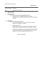
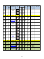
EQUIPMENT INVENTORY
1426 St.Joseph Blvd, Orleans, Ontario
Current Room Future Room
No.
No.
Existing
=(Yes)
Planned
=(No)
Images
Approx.
Weight
Power Requirement
HVAC
Req
Width
Depth
Height
Parts Cab_01.jpg
670 mm
26 in
271 mm
11 in
1520 mm
60 in
500 lbs
N/A
No
Parts Cab 02.jpg
670 mm
26 in
700 mm
28 in
1500 mm
59 in
500 lbs
N/A
No
Parts Cab 03.jpg
670 mm
26 in
700 mm
28 in
1500 mm
59 in
500 lbs
N/A
No
Parts Cab 04.jpg
670 mm
26 in
700 mm
28 in
1500 mm
59 in
500 lbs
N/A
No
Parts Cab 5.jpg
670 mm
26 in
700 mm
28 in
1500 mm
59 in
500 lbs
N/A
No
Parts Cab 06.jpg
670 mm
26 in
750 mm
30 in
1520 mm
60 in
500 lbs
N/A
No
Parts Cab 07.jpg
770 mm
30 in
750 mm
30 in
1520 mm
60 in
500 lbs
N/A
No
Parts Cab 08.jpg
770 mm
30 in
750 mm
30 in
1520 mm
60 in
500 lbs
N/A
No
Parts Cab 09.jpg
670 mm
26 in
690 mm
27 in
1530 mm
60 in
500 lbs
N/A
No
Parts Cab_A.jpg
1200 mm
47 in
630 mm
25 in
1530 mm
60 in
500 lbs
N/A
No
Parts Cab_B.jpg
670 mm
26 in
690 mm
27 in
1530 mm
60 in
500 lbs
N/A
No
Parts Cab_C.jpg
610 mm
24 in
690 mm
27 in
1530 mm
60 in
500 lbs
N/A
No
Parts Cab_D.jpg
670 mm
26 in
685 mm
27 in
1530 mm
60 in
500 lbs
N/A
No
Parts Cab_E.jpg
610 mm
24 in
690 mm
27 in
1530 mm
60 in
500 LBS
N/A
No
[Binder Tab 2]
Room 112
Existing
Room 101
Size (mm)
Equipment Description
Room 112
Yes
13 Drawer Cabinet
Existing
Room 101
Room 112
Yes
10 Drawer Cabinet
Existing
Room 101
Room 112
Yes
10 Drawer Cabinet
Existing
Room 101
Room 112
Yes
10 Drawer Cabinet
Existing
Room 101
Room 112
Yes
9 Drawer Cabinet
Existing
Room 101
Room 112
Yes
13 Drawer Cabinet
Existing
Room 101
Room 112
Yes
6 Drawer Cabinet
Existing
Room 101
Room 112
Yes
6 Drawer Cabinet
Existing
Room 101
Room 112
Yes
13 Drawer Cabinet
Existing
Room 104
Room 112
Yes
8 Drawer Cabinet
Existing
Room 104
Room 112
Yes
13 Drawer Cabinet
Existing
Room 104
Room 112
Yes
13 Drawer Cabinet
Existing
Room 104
Room 112
Yes
10 Drawer Cabinet
Existing
Room 104
Room 112
Yes
13 Drawer Cabinet
Page 1 of 9
Space
Requirements
(around
equipment)
Specialty / Comments
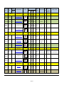
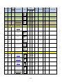
Current Room Future Room
No.
No.
Existing
=(Yes)
Planned
=(No)
Size (mm)
Equipment Description
Images
Approx.
Weight
Power Requirement
HVAC
Req
88 lbs
115/230 V
No
115/230 V
No
Width
Depth
Height
Baldor 2048-151D Sander_1.JPG
457 mm
18 in
357 mm
14 in
1473 mm
58 in
Grinder 01.jpg
860 mm
34 in
350 mm
14 in
1380 mm
GRAFTEX Drill.jpg
1867 mm
74 in
762 mm
30 in
1930 mm
76 in
500 lbs
120 V
No
Standard Lathe.jpg
1630 mm
64 in
510 mm
20 in
1300 mm
51 in
1450 lbs
115V, 10 amps
No
TRUMARK 5000.jpg
860 mm
34 in
1310 mm 2000 mm
52 in
79 in
903 lbs
230v
No
Mitutoyo PH-3500.jpg
460 mm
18 in
1138 mm 1155 mm
45 in
45 in
341 lbs
100/110/120/220/24
0V AC (switchable),
50/60Hz
No
1734 mm 2030 mm 2800 mm
68 in
80 in
82 in
5072 lbs
718 mm
28 in
1845 mm
73 in
1500 lbs
1016 mm 1016 mm 2286 mm
40 in
40 in
90 in
1500 lbs
679 mm
27 in
980 mm
39 in
192 lbs
230V, single phase 60
Hz
75857906.JPG
2340 mm 1190 mm 2450 mm
912 in
47 in
94 in
945 lbs
480 V
Yes
paint bay.jpg
1626 mm 1575 mm 2743mm
64 in
62 in
108 in
wired for 480 V, 3phase 60 hertz unless
otherwise requested
Yes
Space
Requirements
(around
equipment)
Specialty / Comments
Minimum 24"
around and 60"
above Unit
located in a dry, clean, cool, dust
free, & well ventilated area
[Binder Tab 3]
Room 114
Owner Supplied
Room 114
No
Baldor 2048-151D Sander
Owner Supplied
Room 114
No
BALDOR 8107WD Grinder
Existing
Room 104
Room 114
Yes
CRAFTEX Drill Press and Bench
Existing
Room 104
Room 114
Yes
STANDARD-MODERN 1334 Lathe
[Binder Tab 4]
Room 118
Existing
Room 102
Room 118
Yes
TRUMARK STATION 5000
Existing
Room 104
Room 118
Yes
MITUTOYO PH-3500
Owner
Supplied
Room 118
No
ZEISS Contura G2, 10/12/6
4B8D518A.jpg
No
[Binder Tab 5]
Room 125
Existing
Room 141
Room 125
Yes
Compressor DV Systems SC3050
Existing
Room 141
Room 125
Yes
Compressor Tank
Existing
Room 140
Room 125
Yes
ASD 150 Compressor Dryer
DV System.jpg
Compresor tank.jpg
Dryer.jpg
914 mm
36 in
503 mm
20 in
230v3 phase575 3
phase,115v 115 amp
Yes
N0
[Binder Tab 6]
Room 121
Existing
Room 141
Room 121
Yes
FRD 2-35 Oven
Contractor
Supplied
Room 121
No
FAST-PAK Paint Booth
Page 2 of 9
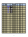
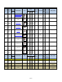
Current Room Future Room
No.
No.
Existing
=(Yes)
Planned
=(No)
Size (mm)
Equipment Description
Images
Approx.
Weight
Power Requirement
HVAC
Req
Width
Depth
Height
Baldor Buffer.jpg
750 mm
30 in
360 mm
14 in
1030 mm
41 in
115/230v
No
Grinder 01.jpg
860 mm
34 in
350 mm
14 in
1380 mm
54 in
115/230
No
Baldor 2048-151D Sander.jpg
457 mm
18 in
357 mm
14 in
1473 mm
58 in
115/230
No
600v 30 amps 3
phase
No
Space
Requirements
(around
equipment)
[Binder Tab 7]
Room 122
Existing
Room 115
Room 122
Yes
BALDOR 332B Buffer and stand
Existing
Room 115
Room 122
Yes
BALDOR 8107WD Grinder
Existing
Room 115
Room 122
Yes
Baldor 4028-151D Sander
Existing
Room 115
Room 122
Yes
CLUSING CS-618 Surface Grinder
Existing
Room 115
Room 122
Yes
DELTA Sander
Existing
Room 140
Room 122
Yes
LITTLE BLASTER, LB 4024-3
Existing
Room 140
Room 122
Yes
Contractor
Supplied
Room 122
No
CS-618.jpg
1473 mm 1016 mm 1803 mm
58 in
40 in
71 in
1500 lbs
Delta Sander.jpg
620 mm
24 in
470 mm
19 in
1250 mm
54 in
115/230v
No
Little_Blaster.jpg
1295 mm
51 in
965 mm
38 in
1702 mm
68 in
120v
No
BLAST-PACT Sand Blaster, Model:
SBP3020-310, Serial :20701
Blast pack.jpg
1219 mm 1219 mm 1524 mm
48 in
48 in
60 in
115V, 60 Hz
No
BLAST-PACT Sand Blaster, Model:
SBP3020-310
B61022AE.JPG
1219 mm 1219 mm 1524 mm
48 in
48 in
60 in
115V, 60 Hz
No
Techleader.jpg
1981 mm 1651 mm 1651 mm
78 in
65 in
65 in
1500 lbs
575 600V, 3 phase
115V 120 amp, 115V
15 amp
No
In the middle of a
10 foot square
space
CD85CCC7.jpg
2530 mm 1620 mm 2150 mm
100 in
64 in
85 in
1500 lbs
600 V, 3phase,220v
6.5 amp 115v 20
amp, 115V 15amp
No
In the middle of a
10 foot square
space
MASTER 3250.jpg
2489 mm 1321 mm 1854 mm
98 in
52 in
73 in
3500 lbs
600 V 3 phase ,115V
20 amps, 115v 15
amps
No
5 feet in front of
560 mm
22 in
300 mm
12 in
1010 mm
40 in
100 lbs
N/A
No
635 mm
25 in
737 mm
29 in
1727 mm
68 in
1500 lbs
600v 30 amps 3
phase, 230 V 3 phase
No
780 mm
31 in
750 mm
30 in
810 mm
32 in
500 lbs
N/A
No
[Binder Tab 8]
Room 124
Existing
Room 115
Room 124
Yes
TECHLEADER Stand Up Mill
Kneemill
Existing
Room 115
Room 124
Yes
BRIDGEPORT Stand Up Mill
Kneemill
Existing
Room 115
Room 124
Yes
COLCHESTER MASTER 3250 Lathe
Existing
Room 115
Room 124
Yes
Red Tool box on wheels
Existing
Room 140
Room 124
Yes
IMA Drill Press
Existing
Room 115
Room 124
Yes
Cabinet with Green Tool Chest
Red Tool Box.jpg
IMA Drilling Press.jpg
06.jpg
Page 3 of 9
Specialty / Comments
Current Room Future Room
No.
No.
Existing
=(Yes)
Planned
=(No)
Equipment Description
Size (mm)
Existing
Room 115
Room 124
Yes
Parts Drawer
Existing
Room 115
Room 124
Yes
Cabinet on wheels
Room 102
Room 124
Yes
SNAP-ON Tool Box (on Wheels)
Owner Supplied
Room 124
No
FANCU Robocut Wire EDM
Owner Supplied
Room 124
No
Matsuura CNC V.Plus 550
Owner Supplied
Room 124
No
Nakamura-Tone SC-200L Single
turning Center
Owner Supplied
Room 124
No
FANCU Robocut Wire EDM
Images
Approx.
Weight
Power Requirement
HVAC
Req
Space
Requirements
(around
equipment)
Specialty / Comments
Width
Depth
Height
Parts Drawer.jpg
860 mm
34 in
300 mm
12 in
1090 mm
43 in
200 lbs
N/A
No
Cabinet .jpg
1220 mm
48 in
610 mm
24 in
1200 mm
47 in
500 lbs
N/A
No
SNAP-ON.jpg
980 mm
39 in
550 mm
22 in
1680 mm
66 in
500 lbs
N/A
No
2134 mm 2410 mm 3048 mm
84 in
95 in
120 in
4620 lbs
200/220v
No
Matsuura CNC.jpg
3090 mm 4065 mm 2730 mm
122 in
160 in
107
8470 lbs
575V/ 3PH/ 60 Cycles
No
NAKAMURA Turning Center.jpg
2771 mm 1884 mm 1965 mm
109 in
74 in
77 in
110231 lbs
575V, 3 ph, 60 Hz
operation
No
FANUC ROBOCUT.JPG
3190 mm 3142 mm 2370 mm
126 in
124 in
129 in
6900 lbs
220 3-PH, 60 HZ
No
Hood 111-96PR.jpg
2438 mm
96 in
832 mm
33 in
2280 mm
90 in
120 V
Yes
Sonic System 1
Branson 8300_1.jpg
446 mm
17.5 in
432 mm
17 in
140 mm
5.5 in
120 V
N0
Sonic System 1
Hood 111-60PR.jpg
1524 mm
60 in
832 mm
33 in
2280 mm
90 in
120 V
Yes
Sonic System 2
Branson 8300_1.jpg
446 mm
17.5 in
432 mm
17 in
140 mm
5.5 in
120 V
No
Sonic System 2
Sonic sink.jpg
610 mm
24 in
953 mm
37.5 in
940 mm
37 in
N/A
No
Sonic System Room
Hood 111-96PR.jpg
2438 mm
96 in
832 mm
33 in
2280 mm
90 in
120 V
Yes
Sonic System 3
2438 mm
96 in
832 mm
33 in
2280 mm
90 in
120 V
Yes
Sonic System 4
Fanuc Robodrill.jpg
[Binder Tab 9]
Room 127
Existing
Room 129 B
Room 127
Yes
H.H. Hawkins Fume Hood, Model
111-96PR
Existing
Room 129 B
Room 127
Yes
Branson 8300
Existing
Room 129 B
Room 127
Yes
H.H. Hawkins Fume Hood, Model
111-60PR
Existing
Room 129 B
Room 127
Yes
Branson 8300
Existing
Room 129 B
Room 127
Yes
Sink
Contractor
Supplied
Room 127
No
H.H. Hawkins Fume Hood, Model
111-96PR
Contractor
Supplied
Room 127
No
H.H. Hawkins Fume Hood, Model
111-96PR
Hood 111-96PR.jpg
Page 4 of 9
30 lbs
30 lbs
Current Room Future Room
No.
No.
Existing
=(Yes)
Planned
=(No)
Equipment Description
Size (mm)
Images
Approx.
Weight
Space
Requirements
(around
equipment)
Power Requirement
HVAC
Req
120 V
Yes
Sonic System 5
Specialty / Comments
Width
Depth
Height
2438 mm
96 in
832 mm
33 in
2280 mm
90 in
Branson 8300_1.jpg
446 mm
17.5 in
432 mm
17 in
140 mm
5.5 in
30 lbs
120 V
No
Sonic System 3
Branson 8300_1.jpg
446 mm
17.5 in
432 mm
17 in
140 mm
5.5 in
30 lbs
120 V
No
Sonic System 4
Branson 8300_1.jpg
446 mm
17.5 in
432 mm
17 in
140 mm
5.5 in
30 lbs
120 V
No
Sonic System 5
Contractor
Supplied
Room 127
No
H.H. Hawkins Fume Hood, Model
111-96PR
Contractor
Supplied
Room 127
No
Branson 8300
Contractor
Supplied
Room 127
No
Branson 8300
Contractor
Supplied
Room 127
No
Branson 8300
Contractor
Supplied
Room 127
No
Branson Transducerized Tanks
New Transducerized tank to
replace existing tank for Sonic
System 1 from room 129 B
Contractor
Supplied
Room 127
No
Branson Transducerized Tanks
New Transducerized tank to
replace existing tankfor Sonic
System 2 from room 129 B
Contractor
Supplied
Room 127
No
Branson Transducerized Tanks
Sonic System 3
Contractor
Supplied
Room 127
No
Branson Transducerized Tanks
Sonic System 4
Contractor
Supplied
Room 127
No
Branson Transducerized Tanks
Sonic System 5
Contractor
Supplied
Room 127
No
Branson Pump and Bag Filter
Sonic System 3
Contractor
Supplied
Room 127
No
Branson Pump and Bag Filter
Sonic System 4
Contractor
Supplied
Room 127
No
Branson Pump and Bag Filter
Sonic System 5
Contractor
Supplied
Room 127
No
Mechanical Timer
Sonic System 1
Contractor
Supplied
Room 127
No
Mechanical Timer
Sonic System 2
Contractor
Supplied
Room 127
No
Mechanical Timer
Sonic System 3
Hood 111-96PR.jpg
Page 5 of 9
Current Room Future Room
No.
No.
Existing
=(Yes)
Planned
=(No)
Equipment Description
Size (mm)
Images
Width
Depth
Height
Approx.
Weight
Power Requirement
HVAC
Req
Space
Requirements
(around
equipment)
Specialty / Comments
Contractor
Supplied
Room 127
No
Mechanical Timer
Sonic System 4
Contractor
Supplied
Room 127
No
Mechanical Timer
Sonic System 5
Contractor
Supplied
Room 127
No
Work Stations for Base
2438 mm
96 in
686 mm
27 in
864 mm
34 in
Sonic System 3
Contractor
Supplied
Room 127
No
Work Stations for Base
2438 mm
96 in
686 mm
27 in
864 mm
34 in
Sonic System 4
Contractor
Supplied
Room 127
No
Work Stations for Base
2438 mm
96 in
686 mm
27 in
864 mm
34 in
Sonic System 5
[Binder Tab 10]
Room 130
Existing
Room 141
Room 130
Yes
Bluing System
Existing
Room 140
Room 130
Yes
Bluing System Tank
Existing
Room 140
Room 130
Yes
Bluing System Tank
Existing
Room 140
Room 130
Yes
Bluing System Control Panel
Existing
Room 141
Room 130
Yes
Phosphate Tank
Existing
Room 141
Room 130
Yes
Rena Tank
Existing
Room 141
Room 130
Yes
Collection Tank
Existing
Room 141
Room 130
Yes
Waste Tanks (x3)
Existing
Room 141
Room 130
Yes
Big Waste Tank
845BFBF2.jpg
3658 mm 1524 mm 2438 mm
144 in
60 in
96 in
115v
4A4DB0D0.jpg
1041 mm
41 in
991 mm
39 in
635 mm
25 in
566DDF5E.jpg
1080 mm
42.5 in
432 mm
17 in
635 mm
25 in
Bueing Control Panel.jpg
610 mm
24 in
305 mm
12 in
1829 mm
72 in
115V
Container.jpg
1067 mm 1067 mm
42 in
42 in
914 mm
40 in
N/A
x3 Container_1.jpg
1067 mm
42 in
607 mm
36 in
N/A
Sq Container.jpg
1219 mm 1219 mm 1067 mm
50 in
48 in
42 in
N/A
607 mm
36 in
1067 mm 1219 mm
42 in
48 in
N/A
1219 mm 1219 mm 1829 mm
50 in
48 in
72 in
N/A
32B3C47A.jpg
Big Waste Container.jpg
610 mm
24 in
Page 6 of 9
Yes
Yes
Current Room Future Room
No.
No.
Existing
=(Yes)
Planned
=(No)
Equipment Description
Size (mm)
Width
Existing
Room 141
Room 130
Yes
Square Tank: x2 Dimension
Combined
Existing
Room 141
Room 130
Yes
J-PRESS 470W100
Rom 137
Images
Depth
Height
Approx.
Weight
Power Requirement
HVAC
Req
1219 mm 1219 mm
48 in
48 in
762 mm
30 in
1600 mm
63 in
711 mm
28 in
1143 mm
45 in
880 mm
35 in
1100 mm 2040 mm
43 in
80 in
VWR 9010L image.jpg
1080 mm
43 in
889 mm
35 in
2159 mm
85 in
OQA Work Bench.jpg
2756 mm
108.5 in
762 mm
30 in
1803 mm
71 in
N/A
OQA Cabinet 1.jpg
1524 mm
60 in
686 mm
27 in
1219 mm
48 in
N/A
No
OQA Cabinet2.jpg
1524 mm
60 in
686 mm
27 in
1219 mm
48 in
N/A
No
OQA Cabinet 3.jpg
838 mm
33 in
686 mm
27 in
1168 mm
46 in
N/A
No
Despatch.jpg
580 mm
23 in
480 mm
19 in
750 mm
29.5 in
120 V
No
PPI_Oh-101.jpg
432 mm
17 in
483 mm
19 in
4812 mm
19 in
120 V
No
2392FEBC.jpg
432 mm
17 in
381 mm
15 in
2711 mm
28 in
86 lbs
120V
No
300 mm
12 in
400 mm
16 in
7 lbs
115/60/1 to 24 VDC
No
C9A1CEC2.jpg
300 mm
12 in
300 mm
12 in
300 mm
12 in
483 mm
19 in
Container 4.jpg
6F8D196D.jpg
Space
Requirements
(around
equipment)
N/A
N0
[Binder Tab 11]
Existing
Room 141
Room 137
Yes
RTHC 28P
Existing
Room 141
Room 137
Yes
Humidity Chamber VWR 9010L
Existing
Room 140
Room 137
Yes
OQA Work Bench
Existing
Room 140
Room 137
Yes
OQA Cabinet 1
Existing
Room 140
Room 137
Yes
OQA Cabinet 2
Existing
Room 140
Room 137
Yes
OQA Cabinet 3
Existing
Room 140
Room 137
Yes
Despatch Oven
Existing
Room 140
Room 137
Yes
PPI OH-101
Room 139A
RTHC 28P.jpg
208-230 V
460 lbs
110 lbs
120 V
[Binder Tab 12]
Owner
Supplied
Room 139A
No
Owner
Supplied
Room 139A
No
Owner
Supplied
Room 139A
No
Navien N P-240A
AXIOM MF200 Mini System Feeder
EXTROL AX-15 Expansion Tank
B9C1E7A4.jpg
Page 7 of 9
No
Clearances - Sides
and Top - 12
in/305 mm
Specialty / Comments
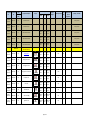
Current Room Future Room
No.
No.
Existing
=(Yes)
Planned
=(No)
Equipment Description
Size (mm)
Owner
Supplied
Room 139A
No
Ballistic Gel Mixer
Owner
Supplied
Room 139A
No
Stainless steel sink and counter top
Contractor
Supplied
Room 139A
No
Room 140
Images
Width
Depth
ED4901FE.jpg
921 mm
36.25 in
737 mm
29 in
B550C978.jpg
1219 mm
48 in
533 mm
21 in
Heatcraft H-1M-CU Cooler
6AF08CA6.jpg
Height
Approx.
Weight
Power Requirement
HVAC
Req
Existing
Room 141
Existing
Room 140
Existing
Room 140
Yes
Snail Systems
Existing
Room 140
Existing
Room 140
Yes
Snail Systems
Existing
Room 140
Existing
Room 140
Yes
Snail Systems
Existing
Room 140
Existing
Room 140
Yes
Savage Range Systems
Existing
Room 140
Existing
Room 140
Yes
Savage Range Systems
876 mm
34.50 in
No
2057 mm 2362 mm 2286 mm
81 in
93 in
90 in
220 V
No
120v and 220 V
No
120v and 220 V
No
120v and 220 V
No
120v and 220 V
No
120v and 220 V
No
Equipment Layout
Room 141
Snail System.jpg
Snail System_1.jpg
Snail System_2.jpg
Savage Range Systems.jpg
Savage Range Systems_1.jpg
[Binder Tab 14]
Existing
Room 140
Existing
Room 141
Yes
SOCO MC-275F
Existing
Room 141
Existing
Room 141
Yes
TENNSMITH HBU48-12
Existing
Room 141
Existing
Room 141
Yes
TENNSMITH T-52
Existing
Room 141
Existing
Room 141
Yes
Existing
Room 141
Existing
Room 141
Yes
SOCO_1.jpg
1000 mm
40 in
750 mm
30 in
1610 mm
63 in
396 lbs
220v
no
TENNSMITH HBU48-12.jpg
1829 mm
72 in
915 mm
36 in
1346 mm
53 in
1330 lbs
N/A
No
TENNSMITH T-52.jpg
1550 mm
61 in
915 mm
36 in
1067 mm
42 in
1330 lbs
N/A
No
DV Compressor System (power
already hooked up)
DV MK 247 compressor system.jpg
1860 mm
71 in
570 mm
22 in
1930 mm
80 in
Power already
connected
Yes
FAST-PAK Paint Booth (power
already hooked up)
paint bay.jpg
575V,
Yes
1626 mm 1575 mm 2743 mm
64 in
62 in
108 in
Page 8 of 9
Specialty / Comments
120 V
[Binder Tab 13]
Equipment
Layout
Space
Requirements
(around
equipment)
Place next to Gel Mixer
Current Room Future Room
No.
No.
Existing
=(Yes)
Planned
=(No)
Equipment Description
Size (mm)
Width
Existing
Room 141
Existing
Room 141
Yes
DIVERSI-TECH Downdraft DD3x4
(Power already hooked up)
Existing
Room 140
Existing
Room 141
Yes
STARTRITE / Horizontal Cut-off
machine
Existing
Room 141
Existing
Room 141
Yes
EMPIRE Sandblaster
Existing
Room 140
Existing
Room 141
Yes
Lincoln 8809 Welder
Existing
Room 141
Existing
Room 141
Yes
TIG 175 Welder
Existing
Room 140
Existing
Room 141
Yes
JHBS- 916 Horizontal Band Saw
Existing
Room 140
Existing
Room 141
Yes
Work Bench
Existing
Room 140
Existing
Room 141
Yes
Work Bench with vice
Existing
Room 141
Existing
Room 141
Yes
Yellow Cabinet
Existing
Room 141
Existing
Room 141
Yes
Oxygen/Acetylene tank cart
Existing
=(Yes)
Planned
=(No)
New Facity
Current Room Future Room
No.
No.
Existing
Room 130
Contractor
Supplied
Contractor
Supplied
Images
Depth
Height
Power Requirement
HVAC
Req
450 lbs
208-230/460/575v
N0
230v
No
115v
No
208/230/460-1-60
N0
1070 mm 1220 mm
42 in
48 in
910 mm
39 in
1300 mm
51 in
740 mm
29 in
1070 mm
42 in
EMPIRE.jpg
914 mm
36 in
610 mm
24 in
1551mm
61 in
Lincoln 8809 Welder.jpg
559 mm
22 in
737 mm
29 in
699 mm
27.5 in
TIG 175 welder.jpg
1000 mm
39 in
230 mm
9 in
1250 mm
49 in
185 lbs
230v
No
1626 mm
64 in
711 mm
28 in
1245 mm
49 in
704 lbs
115/230 V,
Prewired 230 V
No
Bench.jpg
920 mm
36 in
620 mm
24 in
930 mm
37 in
N/A
No
Bench with vice.jpg
1530 mm
60 in
770 mm
30 in
1180 mm
47 in
N/A
No
yellow cabinet.jpg
880 mm
20 in
457 mm
18 in
889 mm
35 in
N/A
No
Oxygen tank banks.jpg
890 mm
35 in
650 mm
26 in
1440 mm
57 in
N/A
No
Power Requirement
HVAC
Req
Downdraft 3x4.jpg
STARTRITE.jpg
JHBS-916.jpg
Size (mm)
Equipment Description
Approx.
Weight
Images
Width
Depth
Height
285 lbs
Approx.
Weight
Space
Requirements
(around
equipment)
Specialty / Comments
Floor Space
Required:
65”x28”
Space
Requirements
(around
equipment)
Specialty / Comments
[Binder Tab 15]
New Facity
Yes
Wood Lab Casework
New Facity
No
Wood Lab Casework
New Facity
No
Countertop
Move nine (9) existing Wood Lab
Casework to new facilty
Three (3) Wood Lab Casework for
new facility
Replace two (2) laminated wood
contertops for existing Wood Lab
Casework
Page 9 of 9
Sonic Clean up Room Equipment Item
Description
1.
Three (3) – VBA-96-FRP-E Vanguard Fume Hoods
Exterior Dimensions – width: 96”, Depth 32 ¾ “, Height: 55”
Balanced Air - White Fibreglass Reinforced Polyester Liner;
1-1/4" Thick Dished Black Epoxy Countertop;
Vertical Sash, S/S Handle;
TEL AFA 500 Airflow Alarm Monitor;
SS316 Airfoil;
Standard pre-wired electrical (120V, 15A Plugs, Switch and T8 FL Light);
1ea A23-48 Flammable Storage;
1ea A2-48 General Storage Cabinet; and
No Mechanical Fixtures Included.
2.
Three (3) – Branson series 8300 Ultrasonic Generator
3.
Five (5) – Branson Transducerized Tanks:
Part#: STD-478-693 CH4012-40·36S;
Ultrasonic load impedance capacitance;
RF voltage;
Frequency compatible with S8340·36 generator;
Working watts thermostatically controlled;
Material construction 316 stainless steel;
230 V/ 1ph; and
Hard chromed emitting face to extend tank life.
4.
Three (3) – Branson Pump and Bag Filter
Part # STD-246-975;
Stand alone pump and big filter unit includes on/off switch, and
Line cord and interconnecting hoses for CH-Tank.
5.
Five (5) – Mechanical Timer
Part # STD-410-901;
0-60 minute mechanical timer; and
Includes one OEM I/O kit.
6.
Three (3) – Work Stations for Base
7.
Each will be a combination of two work stations with a common leg;
Overall dimensions of each will be 27” x 96” @ 34” high. Leg extensions allowing an
extra 3” in height are included as well as levelling glides for all leg assemblies;
Each (double) bench will consist of one bench 27” x 60” and one bench 27” x 36”;
Each will have a rear stringer and side panels on the outside leg only;
Each bench will have two 12” deep stainless steel shelves below the work surface;
and
Each bench will have a set of sliding doors below the work surface.
General – Applies to all Sonic cleaners ( New and Existing)
Sonic Clean up Room Equipment
Compressed air outlet to terminate at each sonic cleaner with 6 feet of hoes and air
nozzle gun.
Sonic System requires onsite testing, balancing and commissioning.
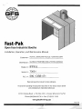
Fast-Pak
Open Face Industrial Booths
Installation, Operation, and Maintenance Manual
Customer: ROYAL CANADIAN POLICE / ONTARIO SPR
Distributor: GLOBAL FINISHING SOLUTIONS-CANADA
Model #:
IFPX-5
Serial #:
73031
-------------------------
590/088-471
P.O. #: ________________________
_
Read and keep this manual for future reference.
All personnel operating the equipment described in this manual should review
and understand all instructions before use.
12731 Norway Road • P.O. Box 250 • Osseo, Wisconsin 54758
Phone:(800)848-8738 • Fax: (715)597-2193
www.globalfinishing.com
R.,~ion :
3-1<HJ6
Table of Contents
> Warranty
................................... . ...................3 > Information and Introduction ....................................... .4 • How to Use This Manual
• A Message for the Purchaser
• Product Description
> Safety Information ................................................5 •
•
•
•
General Safety
Safety Notes
Safety Precautions
Canadian Standards (CR90-003)
> Pre-Assembly ...................................................10 • Before Installation
• Unpacking
• During Assembly
> Assembly and Operation Instructions ................................11 • Assembly Instructions
Step 1: Panel Assembly
Step 2: Filter Assembly
Step 3: Lighting
Step 4: Exhaust Fan Assembly
Step 5: Manometer Assembly
Step 6: Roll Media Hanger Assembly
Step 7: Safety/Warning Labels
Step 8: Work Depth Extension Kits
Step 9: Standard Control Panel/Control Package
• Operating Instructions
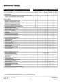
> Maintenance ....................................................16 • Maintenance Instructions
• Maintenance Schedule
• Troubleshooting Guide
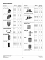
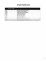
> Department Reference Guide ......................................19 > Accessories ....................................................20 •
•
•
•
Other Accessories
Miscellaneous Duct Detail
Ballast Warranty
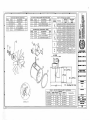
Parts List
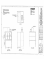
> Mechanical Drawings
GLOBAL FINISHING SOLUTIONS'"
(800)848-8738
www.globalfinlshlng.com
2
Revision: :>-14-00
~
"
-
•
, " " . .
\
\'
\
'
..
L
J ','.
"',"
•• ,
."
/"
-"
,,',..
• \..'
,(,
,',
• ,
~
GFS
~
Limited Warranty
GLOBAL (the Sellers) warrants to the original end-user buyer (the buyer) that the equipment manufactured by. and purchased from. the
Seller (the Equipment). if properly installed in accordance with the Seller's Service Manual, operated. and maintained, and used under
normal conditions, shall be free from defects in workmanship and materials for a period of one (1) year from the date the Equipment is
shipped from the facilities of the Seller_ The obligation of the Seller, and the Buyer's SOLE AND EXCLUSIVE REMEDY hereunder, shall be
limited to one of the following, at the Seller'S option:
(01) The repair or replacement of defective parts or components (collectively, the Parts) of the Equipment; provided, however,
the Buyer shall be responsible for the payment of all labor costs associated with any such repair or replacement.
(02) In the event the Seller is unable to repair or replace the defective Parts, the Buyer shall be entitled to a refund of the cost of
the Parts.
The Seller shall have no obligation under this Limited Warranty for ordinary wear and tear of the Equipment; if installation of the
Equipment does not comply with local, state and federal requirements or laws; or if the Equipment is modified by any other person or
organization. The Seller makes no warranty of any kind whatsoever with respect to Parts, which are manufactured or supplied by other
persons or organizations (an OEM); provided, however, the Seller shall reasonably assist the Buyer in connection with warranties, if any,
provided by an OEM.
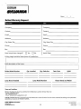
Warranty Performance Procedures
In the event the Buyer believes the Seller may be responsible for the performance of any warranty obligation, the Buyer must immediately
send written notice of a claimed defect, and must immediately refrain from any further use of the affected Equipment. No attempted repair
of the claimed defect may be made without the prior written consent of the Seller. Before any Parts can be returned to the Seller, the Buyer
must contact the Seller and request a Return Authorization. Upon the Buyer's receipt of the Return Authorization form, the Parts may be
shipped, freight prepaid, to the facility designated on the Return Authorization. All Parts retumed for repair, replacement, or refund (a
refund may be made in the form of a credit to the Buyer's account), must be accompanied by the Return Authorization. All returned parts
are subject to a thirty percent (30%) handling charge. Parts manufactured or supplied by an OEM are subject to the warranties, if any
provided by such OEM's; and repair or replacement of such Parts are subject to the approval of the OEM. The Buyer shall be responsible
for the payment of any handling or restocking charges associated with OEM Parts.
D;scla;mers
of Warrant;es
THE WARRANTIES CONTAINED HEREIN ARE EXPRESSLY IN LIEU OF ANY OTHER EXPRESSED OR IMPLIED WARRANTIES, OR ANY OTHER
OBLIGATION ON THE PART OF THE SELLER, INCLUDING WITHOUT LIMITATION, ANY IMPLIED WARRANTY OF MERCHANTABILITY OR FITNESS
FOR A PARTICULAR PURPOSE. ANY MODELS, DRAWINGS, PLANS, SPECIFICATIONS, AFFIRMATION OF FACT, PROMISES, OR OTHER
COMMUNICA TIONS BY THE SELLER WITH THE REFERENCE TO THE EQUIPMENT OR THE PERFORMANCE OF THE EQUIPMENT ARE SOLEL Y FOR
THE CONVENIENCE OF THE BUYER AND SHALL NOT IN ANY WAY MODIFY THE EXPRESSED WARRANTIES AND DISCLAIMERS SET FORTH
HEREIN. THE BUYER ACKNOWLEDGES IT IS PURCHASING THE EQUIPMENT SOLEL Y ON THE BASIS OF THE COMMITMENTS FOR THE SELLER
AS EXPRESSLY SET FORTH HEREIN. NO AGENTS OR OTHER PARTIES ARE AUTHORIZED TO MAKE ANY WARRANTIES ON BEHALF OF THE
COMPANY OR TO ASSUME FOR THE COMPANY ANY OTHER LIABILITY OR OBLIGA TlON IN CONNECTION WITH THE EQUIPMENT.
Consequent;al Damages
The Seller shall not be liable for any incidental or consequential damages arising from the use of the equipment by the Buyer, the breach
of any warranties, the failure to deliver, delay in delivery, delay on nonconforming condition, or for any other breach of contract or duty
between the Seller and the Buyer.
Um;tatjon
of Actjons
Any action resulting from the breach of any warranty contained herein by the Seller must be commenced within one (1) year after the cause
of action accrues. In no event shall the Seller's total liability for any or all breaches of any warranty exceed the actual purchase price paid
by the Buyer for the Equipment.
12731 Norway Road • P.O. Box 250 • Osseo , Wisconsin 54758-0250
Phone: (800) 848-8738 • Fax: (715) 597-2193
www.globalfinishing.com
3
Revision: :),14-00
Product Description
General Information This paint spray booth provides a controlled
area to safely apply spray paints when installed
with the proper fan and electric motor. Spray
booth construction and recommended airflow
velocities are designed to meet appropriate OSHA
and NFPA 33 regulations.
IMPORTANT!
Read and save these instructions before
attempting to assemble, install, operate, or
maintain the product described. Protect yourself
and others by observing all safety information.
Failure to comply with instructions could result
in personal injury and/or property damage.
Retain these instructions for future reference.
Unless otherwise specified, all booths are
shipped complete with heavy-duty exhaust fans, a
totally enclosed fan-cooled motor, man access
door(s) (optional), product doors (optional),
manometer, fluorescent light fixtures, intake filters
(optional), and exhaust filters with grids, all
necessary hardware, and assembly drawings.
How to Use This Manual
This manual contains instructions for the safe
installation, operation, and maintenance of your
paint spray booth. Please read the Safety
Information section of this manual before you
unpack and assemble the booth.
IMPORTANT!
This equipment is designed expressly for the
removal of particulate matter only. Reduction of
volatile organic compounds (Voes) requires
either coating reformulation or optional,
additional equipment.
Introduction
A Message for the Purchaser
The management and employees at Global
would like to thank you for selecting our product
for your industry. Our product conforms to
Occupational Safety & Health Administration
(OSHA) and National Fire Prevention Association
(NFPA) regulations for your safety. The employees
of Global understand the importance of a quality
system and strive to manufacture the best product
on the market.
GLOBAL FINISHING SOLUTIONS'"
Genera/Information & Introduction
(800)848-8738
www.globalflnlshlng.com
4
Revision: 3-14-06
Safety Notes
Safety Information
• The product must be installed and serviced
only by a trained, qualified service
technician . Incorrect installation may void
the warranty.
IMPORTANT!
This manual contains statements relative to
worker safety. Read this manual thoroughly and
comply as directed. Operate this equipment in
accordance with the guidelines set forth in this
manual. It is impossible to list all potential
hazards of this equipment. Instruct all
personnel involved with this equipment in the
safe conduct and operation of the system.
Global recommends that only qualified
personnel operate and maintain this equipment.
• All persons who will operate, service,
inspect, or otherwise handle this product
must read and understand the safe operating
practices, safety precautions, and warning
messages in this documentation.
• Disconnect and lock out the main electrical
service before installing, adjusting, or
servicing the product.
• Electrical installation should be completed
by a qualified electrician. Installation must
meet all applicable national, state, and local
electrical codes.
General Safety
Operation and maintenance of this product
must be performed properly by qualified
personnel who observe the warnings in all
documentation and notes provided with and on
the product.
• Ensure that all electrical components are
grounded to a central ground.
• Become familiar with all controls.
• Safety signs, panels, and labels that are
normally affixed to the product must be
replaced immediately if illegible or missing.
Follow all general standards for installation and
safety for work on installations. Follow all good
practices for the proper use of lifting tackle and
equipment. The use of protective equipment such
as safety goggles and protective footwear must be
considered.
• New or replacement parts that are installed
during repair or maintenance must include
all safety signs, panels, and labels as
specified by the manufacturer. These must
be affixed to the new or replacement parts as
specified by the manufacturer.
If any pumps or compressors are included as
part of this installation, they must be connected in
compliance with data in the documentation
provided.
• Some spray activities may require the use of
respiratory protection.
IMPORTANT
Portable fire extinguishers need to be provided
and located in accordance with NFPA 10.
Guards and covers that prevent contact with
electrically energized or moving parts are required
and must not be removed or left open during
operation.
Sound pressure levels over 85 decibels may
cause damage to your health. Where applicable,
use earplugs or take other safety measures to
protect yourself.
GLOBAl FINISHING SOLUTIONS'"
Safety Information
(800)848-8 73 8
www.globalflnlshlng.com
5
Revioon : 3-14-06
Safety Precautions
• Duct the exhaust air from the fan away from
the working environment to the outdoors.
(Do not operate the paint booth unless
exhaust has been ducted properly.)
• Install the booth in compliance with the
standards of the NFPA.
• Comply with all local electrical, safety, and
fire codes and regulations, the National
Electrical Code (NEC), and OSHA guidelines.
• Isolate the outdoor vent from air-conditioning
intakes, windows, and any other equipment
that may re-circulate the exhaust indoors.
• Turn the exhaust fan on before using the
spray booth. Ensure that the exhaust fan is
operating correctly before entering the booth.
• Do not overfill the manometer, allowing fluid
to collect in the flexible plastic connecting
loop in the back of the manometer. This
could cause a serious reading error. If the
manometer is subject to overflow, make sure
that the fluid has not passed into the plastic
connecting loop.
• All field wiring provided must comply with
local codes or, in the absence of local codes,
the National Electrical Code (NFPA 70).
• All wiring conform to the latest NEC codes
500, 501, 502, 505, 516.
• Check local codes to see if a booth interlock
is required. A booth interlock will prevent the
spray devices from operating unless the
booth fan is operating.
SAFETY HAZARD!
There are inherent hazards associated with the
operation and service of this equipment. For your
personal safety, observe all of the safety
information. Failure to observe these safety
practices can result in personal injury or death.
• Local fire and building codes may require fire
protection. Check with local inspector
authorities for requirements.
• A fire suppression system (sprinklers or dry
chemical) is required by the NFPA. A fire
suppression system is not supplied with
this booth.
• The use of a solenoid valve is required by the
NFPA. Solenoid valves are not supplied with
this booth except by optional purchase.
• Use an OSHA-approved paint spray respirator
when spraying in the booth.
• Do not operate the spray booth when the
manometer indicates the filter pad needs to
be replaced.
• Treat used arrestor filter pads and any other
paint-contaminated items as flammable
products and dispose of them properly
and safely.
GLOBAL ANISHING SOLlfflONS'"
(800)848-8738
www.globalfinlshlng.com
Safety Information
6
Revision: 3-14-06
Canadian Standard (CR90-OO3)
General Safety Information
6. Fuel piping, components, and accessories external
to the spray booths shall comply with the
provincial/ territorial installation code recognized
by the authority having jurisdiction for the fuel
being supplied or, in the absence of such a code,
then in compliance with CAN/CGA-B149.1 "Natural
Gas Installation Code" or CAN/CGA-B149.2
"Propane Installation Code", as applicable.
1. The location of spray booths for finishing
operations, shall comply with the provincial/
territorial building code recognized by the authority
having jurisdiction or, in the absence of such code,
then in compliance with the current National
Building Code of Canada.
a
Toutes sources de gaz, accessoires, etc, situes
I'ex.terieur de la cabine doivent etre en accordance
avec Ie Code du batiment local, en cas qu' un code
local n 'existe pas I'emplacement doit etre en
accordance avec CAN/CGA-B149.1 "Natural Gas
Installation Code" or CAN/CGA-B149.2 "Propane
Installation Code", as applicable.
L 'emplacement des cabines de peinture utilisee
pour la pulverisation doit etre en accordance avec
Ie Code du batiment local, ou dans Ie cas
d'absence d'un tel code I'emplacement doit etre en
accordance avec Ie Code National du Canada.
2. The required exhaust duct(s) for a spray booth
shall complywith the provincial/territorial building
code recognized by the authority having
jurisdiction or, in the absence of such code, then in
compliance with the current Fire Code of Canada.
7. Space-heating appliances, steam pipes, and other
hot surfaces shall not be located in an area where
deposits of combustible residue may accumulate.
Les radiateurs independents, conduits de vapeur,
et toutes autres sources de chaleur ne seront pas
en proximites des residus de peinture inflammable.
Le conduit exige d'echappement (les conduits)
pour une cabine de pulverisation fera complywith
Ie code de Mtiment provincial/territorial reconnu
par I'autorite ayant la juridiction ou, en I'absence
de tel code, alors en conformite avec Ie Code de
Feu actuel de Canada.
8. Open flames or spark producing devices shall not
be used in a spraying area.
Ouvrir des flammes ou /'etincelle produisant des
appareils ne seront pas utilises dans un secteur
vaporisant.
3. A separate exhaust duct shall be provided for each
spray booth, except that a common duct may be
used if it serves spray booths having a combined
open frontal area of not more than 1.7m2.
9. Where wiring or electrical equipment is located in
areas in which flammable gases or vapors,
combustible or electrically conductive dusts or
combustible fibers are present in quantities
sufficient to create a hazard, such wiring and
electrical equipment shall comply with CSA C22.1
Canadian Electrical Code, Part I sections 18 & 20.
Chaque cabine de peinture doit avoir son pr?pre
canal du ventilateur d'extraction, une exceptIon
existe seulement quand un canal est utilise pour
des cabines qui ont une surface ouverte devancee
qui n'excede pas 1.8m2.
Dans les endroits oD /'equipement electrique, ou
les {ils electriques sont situes proche des residus
de peinture, des vapeurs de peinture, etc.,
facilement inflammable dans des quantitees
suffisantes pour creer un hazard, les {ils et
/'equipement doivent etre en accordance avec CSA
C22.1- Canadian Electrical Code, Part I sections
18 & 20.
4. Mechanical Ventilation shall be provided in all
spraying areas with sufficient air movement to
prevent dangerous flammable vapor or powder
concentrations.
La ventilation mechanique doit etre adequate
proche des zones de pulverisation pour empecher
des residus de peinture facilement inflammable de
s 'ebaucher.
10. All electrical equipment within the spraying area,
including lighting fixtures, shall conform to sub
clause 1.13.6.2 unless separated from the spraying
area by vapor-tight separations with no openings.
5. Filters in ducts used to ventilate spray areas shall
be made from noncombustible material or have a
rate of combustibility no greater than Class II filters
conforms to CAN4-S111, The Standard Method of
Fire Tests for Air Filter Units.
Tout equipement electrique et toute forme
d'eclairage I'interieur de la zone de pulverisation
doivent etre en accordance avec I 'article 1.13.6.2.
Une exception existe seulement si la zone de
pulverisation est separe par une pare-vapeur.
a
Les {iltres dans les canals de ventilation des zones
de pulverization seront de materiaux non
combustibles ou doivent avoir un taux de
combustibilite qui n 'excede pas les {iltres Class /I et
qui conforment au CAN4·S111, The Standard
Method of Fire Tests for Air Filter Units.
GLOBAL ANISHING SOLUTIONS'"
(800)848-8738
www.globalftnlshlng.com
Safety Information
7
R"';sion: 3-14-06
Liquides inflammables et combustibles pour
I'usage dans vaporiser de secteurs seront
emmagasines et seront contr61es conformement au
Code de Feu Provincial/Territorial reconnu par
I'autorite ayant la juridiction ou, en I'absence d'un
tel Code, alors conformement au Code de Feu
National de Canada.
La note: jamais fera la quantite de /iquides
inflammables et combustibles dans Ie secteur
vaporisant depasse 1 provision du jour.
11. Electrical wiring, components and accessories
external to the spray booth shall comply with the
provincial! territorial building code recognized by
the authority having jurisdiction or, in the absence
of such code, then in compliance with the current
Canadian Electrical Code .
L'installation electrique electrique, components et
les accessoires externes ii la cabine de
pulverisation se conformeront au provincial/Ie
code de batiment territorial reconnu par I'autorite
ayant la juridiction ou, en I'absence de tel code,
alors en conformite avec Ie Code Electrique,
canadien et actuel.
4. Filers shall not be used when applying spray
material that is highly susceptible to spontaneous
heating.
Filers ne sera pas utilise en appliquant Ie materiel
de pulverisation qui est extremement susceptible
au chauffage spontane.
Flammable and Combustible Liquids/ Liquides
inflammables et Combustibles
1. Where flammable liquids are supplied to spray
nozzles by a positive displacement pump, the
pump discharge line shall be provided with a
suitable relief valve either discharging to the pump
suction or to a safe remote location .
Paint, Thinners and Solvents/ La peinture,
Thinners et les Oissolvants
1. Paint shall be kept in closed containers when not in
use.
OU les liquides inflammables sont fo urn is pour
vaporiser des jets par une pompe de deplacement
positive, la Iigne de decharge de pompe sera
fournie avec une soupape de soulagement
convenable ou dechargeant ii la succion de pompe
ou ii un emplacement eloigne sOr.
La peinture sera gardee dans les recipients fermes
quand pas dans I'usage.
2. Thinners and solvents shall be dispensed only from
containers that comply with the provincial/
territorial fire code recognized by the authority
having jurisdiction or, in the absence of such a
code, then in compliance with National Fire Code
of Canada.
2. Where flammable or combustible liquid finishes
are being applied in a spray booth, combustible
residue shall be removed from the spraying area
and put in receptacles which comply with the
provincial/Territorial Fire Code recognized by the
authority having jurisdiction or, in the absence of
such a Code, then in receptacles which comply
with the National Fire Code of Canada.
Thinners et les dissolvants seront seulement
dispenses des recipients qui se conforment au
code de feu provincial/territorial reconnu par
I'autorite ayant la juridiction ou, en I'absence d'un
tel code, alors en conformite avec Ie Code de Feu
National de Canada.
OU les fins inflammables ou combustibles /iquides
sont appliquees dans une cabine de pulverisation,
Ie residu combustible sera enleve du secteur
vaporisant et a mis dans les prises qui conforme au
Code de Feu provincial/territorial reconnu par
I'autorite ayant la juridiction ou, en I'absence d'un
tel Code, alors dans les prises qui conforment au
Code de Feu National de Canada.
3. Flammable and combustible liquids for use in
spraying areas shall be stored and handled in
accordance with the Provincial/territorial Fire Code
recognized by the authority having jurisdiction or,
in the absence of such a Code, then in accordance
with the National Fire Code of Canada.
Note: At no time shall the amount of flammable
and combustible liquids in the spraying area
exceed 1 day's supply.
GLOBAL FINISHING SoumONS'"
Safety Information
(800)8 48·8738
www.globalflnlshlng.com
8
ReVision: 3- 14-06
Fire Protection Equipment! Vider I'Equipement de
Protection
Maintenance Instructions
1. Sprinkler head protectors shall be replaced before
they have accumulated excessive deposits.
1. Portable fire extinguishers shall be installed near
all spraying areas in compliance with the
provincial/territorial fire code recognized by the
authority having jurisdiction or, in the absence of
such a code, then in compliance with National Fire
Code of Canada.
Les protecteurs de tete d'arroseur seront remplaces
avant qu'ils ont aient accumute des depots
excessifs.
2. All discarded filter pads and filter rolls shall be
removed to a safe location or placed in a water
filled metal container and disposed of after each
day's operation.
Les extincteurs d'incendie portatifs seront installes
pres de tous secteurs vaporisant en conformite
avec Ie code de feu provincial/territorial reconnu
par I'autorite ayant la juridiction ou, en I'absence
d'un tel code, alors en conformite avec Ie Code de
Feu National de Canada.
Tout filtre rejete rembourre et filtre des rouleaux
sera enleve un emplacement sur ou place dans
un recipient en metal eau-rempli et a Iiquide apres
chaque operation du jour.
a
2. Where a Spray room is used, automatic sprinkler
protection shall be proved throughout the spray
room in compliance with the Provincial/territorial
building code recognized by the authority having
jurisdiction or, in the absence of such a code, then
in compliance with the National Building Code of
Canada.
3. Ovens and associated ductwork shall be inspected,
cleaned, and maintained internally and externally
at sufficient intervals to prevent the accumulation
of combustible deposits.
Les fours et ductwork associe seront inspectes, sera
nettoye et sera maintenu interieurement et en
apparence aux intervalles suffisants pour empecher
I'accumulation de depots combustibles.
OU une piece de Pulverisation est utilisee, la
protection d'arroseur automatique sera prouvee
travers la piece de pulverisation en conformite avec
Ie code de bCitiment Provincial/Territorial reconnu
par I'autorite ayant la juridiction ou, en I'absence
d'un tel code, alors en conformite avec Ie Code de
Batiment National de Canada
a
GLOBAL ANISHING SOLunONS'"
Safety Information
(800)848-8738
www.globalflnlshlng.com
9
ROVIsion: :!-14-06
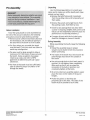
Unpacking
Pre-Assembly
Use the following guidelines to unpack your
crates and to make sure all the booth parts have
arrived and are intact:
• Remove the light fixture and manometer
from the packing crates and temporarily set
them aside.
IMPORTANT!
Before assembly, determine whether you need
a top exhaust or rear exhaust. The assembly
steps are for top exhaust installation. If you
need a rear exhaust, simply interchange the
center back panel with the top panel.
• Remove the panels and angle braces from
the packing crates. Sort them by size.
• Check for any damage that may have been
caused in shipping. (Slightly bent panels and
braces can be straightened and will cause no
performance or assembly problems.)
Before Installation
Since the spray booth is to be assembled on
the site of the actual installation, the following
precautions must be taken before assembly:
• There must be sufficient overhead clearance
for the exhaust unit and exhaust piping in
the area where the booth is to be located.
• Compare all parts with the included parts
sheet for shortages or losses in transit.
During Assembly
While assembling the booth, keep the following
in mind:
• Follow the assembly steps in proper
sequence and double-check the procedure
before continuing.
• The floor where you assemble the booth
must be level. If not, you must use shims to
avoid any misalignment.
• The area must be large enough to allow a
minimum of 3 ft [914mmj. of space around
the booth. Some exceptions may apply.
Check local codes and refer to NFPA
guidelines to determine particular space
allowances.
• The inside of the booth must be smooth-all
panel flanges must be on the outside of
the booth.
• Use only enough bolts to hold each panel in
position. Do not tighten them completely.
After each section is set up, place the
remainder of the bolts in position and
completely tighten all the bolts.
• The front of the booth must be sufficiently
open to allow for proper circulation of air
through the booth.
• At corners where an assembly angle is used,
place the nuts on the inside of the panel
flanges.
• Plumb the panels so that they are
perpendicular to the floor. The sides of the
booth must be parallel to each other.
GLOBAL ANISHING SOLUTIONS'"
(800)848 ·8738
www.globalflnlshlng.com
Pre-Assembly
10 Revision: 3-14-CIi
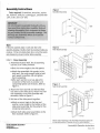
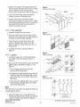
Assembly Instructions
Rgure 1
Back Wall Assembly
Tools required: Screwdriver, wrenches, socket
set, hammer, drift pin, caulking gun, and drill with
l/S", 3/S", and 1/2" bits.
IMPORTANT!
Do not attempt to assemble the booth until you
have read these instructions carefully. Study all
drawings thoroughly. Each component is shown
by part number on the assembly drawings. This
will help you determine where to install the
various components.
---
NOTE
Follow the assembly steps in order and refer to the
assembly drawings. Double-check the procedure before you
continue. If it has not already been done, sort all the panels
and channels by size and number before assembly.
Rgure 2
Filter Rack Assembly
STEP 1: Panel Assembly
1. Assemble the back wall. For all assembly,
use the 5/16" bolts provided.
Filter Chamber
WaN Assembly
• Bolt the corner angles to the side panels.
• Attach the assembled side panels to the
back wall. Use only enough bolts to hold
each panel in position. Do not tighten
them completely.
• After each section is set up, place the
remainder of the bolts in position and
completely tighten all the bolts. Refer to
Figure 1.
Filler Rack
Side
Figure 3
Side Panel Assembly
2. Attach the floor channel and the two filter
rack sides to the filter racks. Attach the filter
rack assembly to the filter chamber wall
assembly. Refer to Figure 2.
_
TOP VIEW
3. Bolt two of the side panels together.
• Attach a corner angle to the top and
another corner angle to the bottom of the
side panel assembly. Do the same for the
remaining side panels.
Side Panel
Side Panel
• Attach both side panel assemblies to the
filter chamber. Refer to Figure 3.
Please note al/ drawings in the Assembly Instructions section are
for example purposes. Drawings are not in exact proportion.
GLOBAL RNISHING SOLUnONS'"
Assembly & Operation Instructions
(800)848·8738
www.g\obalfln/sh/ng.com
11
Revision: :HI-{}6
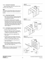
4. Attach the chamber ceiling panel(s) to the
filter chamber followed by the booth ceiling
panels. Attach the fire curtain to the
front, booth ceiling panel. Refer to Figure 4.
Figure 4
Ceiling Panel Assembly
~
_ _ Ch8mber
5. Caulk all connecting joints and interior
seams to ensure a dust-tight seal.
6. Square and anchor the booth. Global
recommends using concrete anchors. Space
them approximately every two ft. around the
perimeter of the booth or as needed to
anchor the booth securely.
Fifter Chamber
STEP 2: Filter Assembly
1. Remove the grid from the carton.
Figure 5
2. Push the rubber tips onto the ends of the
filter grid. The rubber tips are adjustable for
a friction -fit into the filter opening.
Filter Assembly
Dense orAir
Leaving Side
(Tighl Weave)
3. Place the grid into the openings in the
exhaust chamber filter racks. Place the
filters so that the dense side faces the air
leaving side.
I>i, Flow
4. Complete the filter assembly. Refer to Figure 5. Figure 6
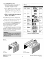
Lighting Assembly
STEP 3: Lighting
In&er1 cage
nUllnio
1. Install the cage nuts into the light fixture
box. Refer to the instructions shown in
Figure 6.
sq u.a re hcl~ .
Snap cag e
nul lnlo hole.
2. Next, from the inside of the booth, install the
lighting fixture box Refer to Steps 1 - 4 in
Figure 7:
..- ,
a. Tilt the lighting fixture box into the
opening of the light panel.
b.5traighten the lighting fixture box then tilt
inward so that the two flanges (A) on the
top of the fixture are on either side of the
light panel.
Figure 7
Lighting Assembly
Slep
CD
c. Slide down the lighting fixture box so that
Slep
@
G)
Slep
0
l-- l-- l-
the two bottom flanges (B) are on either
side of the light panel.
~~
U.
J J J
NOTE
If the light fixture is accessible from outside the booth, you
may skip steps 2a. and 2b.
I
3. Attach the light cover using eight (6mm x
20mm) cap head screws. These are located
under the ballast cover Refer to Figure 6.
~
Front ProtiIo 01 Ugh! Fixture
GLOBAL ANISHING SOLlJTIONSlII
(800)8" 8·8 73 8
www.globalflnlshlng.com Slep
Assembly & Operation Instructions
12
Revision: :!-14-oo
Figure 8
STEP 4: Exhaust Fan Assembly
Exhaust Fan Assembly
Attach the exhaust fan to the roof of the filter
chamber. Refer to Figure 8.
NOTE
The direction of the fan blade rotation and the direction of
the airflow is indicated on the outside of the exhaust fan
housing.
STEP 5: Manometer Assembly
1. Mount the manometer outside of the booth
at a convenient location approximately 5 ft.
[1524mmj from the floor.
Figure 9
2. Drill holes for tubing. Run the supplied
tubing from the manometer to the filter bank.
Run tubing from the low pressure side of the
manometer to the chamber side of the filters.
Run tubing from the high pressure side of the
manometer to the booth side of the filters.
Refer to Figure 9.
Manometer Assembly
.........",'\
low Pressure \
line To Chamber \
Side of Filters
STEP 6: Roll Media Hanger Assembly (OptionaQ
Chamber Flange
1. Remove the grid from the carton.
-'
_............. , .. , /
\
/
2. Push the rubber tips onto the ends of the
filter grid. The rubber tips are adjustable for
a friction-fit into the filter opening.
3. Place the grids into the openings of the
filter racks.
Figure 10
4. Install the J-Strip and Hanger to the panel
above the filter racks, at least 1 to 2 inches
[25mm to 51mmj above the filter rack.
Roll Media Hanger Assembly
5. Tuck roll media up into J-Strip and pull it
down onto Hanger.
6. Roll media and booths each vary in width.
Cut or overlap.roll media as needed to cover
filter wall. Refer to Figure 10.
NOTE
Filler Chamber
Roll filter media is not included. Various types are available
for different designs for specified applications.
t1
S-Min
!"IF', ) •
J.Str,p
Use ",4 x 3/4-
Tel< Sctews
Hang&f
SIDE VIEW GLOBAL ANISHING SOLUTIONS'"
Assembly & Operation Instructions
(800)848·8738
www.globalflnlshlng.com
13
Revision::l-IW6
STEP 7: Safety/Warning Labels
Figure 11
1. Warning labels that are normally affixed to
the booth/product must be replaced
immediately if illegible or missing.
Safety/Warning Labels
2. New or replacement parts that are installed
during repair or maintenance must include
all safety signs, panels, and warning labels
as specified by the manufacturer. These must
be affixed to the new or replacement parts as
specified by the manufacturer.
254-018
(Not on
3. Attach all safety signs and warning labels as
specified. Refer to Figure 11.
labeO
--
1iI
--
----
--"_<1
----'II
--_.
-....
--_
OSHA&
NFPA 33
Fire Curtain
254 -080
WARNING
No Welding
Front or Most
Vis ible location
LA-2066
WARNING
Explosion Hazard,
No Smoking/Open
Flame, Personal
Injury, etc.
Exhaust
Chamber
LA-2077
DANGER
Electrick Shock
Keep Hand Clear
Exhaust Fan
LA-218
Operation &
Maintenance
Side Panel
or by Personnel
Door
LA-219
Riter
Specification
Panel or
Exhaust
Chamber
STEP 8: Work Depth Extension Kits (Optional)
Optional Work Depth Extension Kits expand the
size of your spray booth. Refer to Figure 12.
The extension kit includes 18-gauge galvanized
panels with 2-inch [51mm] flange and holes on
6-inch [152mm] centers with all hardware,
including nuts, bolts, and tie angles.
The light fixture kit includes 48-inch [1219mm]
(4 lamp) ETL listed fluorescent inside access light
fixture(s). Although not standard, a LlL listed light
is available upon customer request.
IMPORTANT!
All paint spray booths must be exhausted to the
outside in accordance with local codes and
NFPA regulation 33.
All labels can be replaced using Part #:
IN5-GFS
Figure 12
Extension Kit
For Booths:
6', 8' & 10' Wide
For Booths:
12',14',16',18' & 20' Wide
GLOBAL FINISHING SOLUTIONS'"
Assembly & Operation Instructions
(800)848-8738
WWN.globalflnlshlng,com 14
Revision: :l-14-<l6
Operating Instructions
STEP 9: Standard Control Panel/Control Package
(Optional)
1. Turn the power on at the main breaker/
disconnect. (This is a black handle on the
face of the control panel.)
Some booths may require custom panels or
multiple control packages based on their fan
configurations and number of motors.
ControlPati61S
,
2. Turn the lights off/on switch to the on position.
3. Momentarily press system start to enter the
booth start-up sequence and operation. After
pressing the system start button, the system
energized light will come on. Then the
exhaust unit on light will come on.
Control Packages
UL 508 & CUL Listed. Standard
panels for a maximum of 6 (4 tube
light fixtures). Each NEMA·IPanel
Enclosure includes the following:
Control packages allow you to order one
number and rec eive all the individual
components for the necessary electrical
controls for a specific booth model. Each
kit includes the following:
• Panel mounted disconnect
• Fused disconnect with fu ses
• Magnetic motor starter with
overloads
• Magnetic motor starter with overload
heater and 120V control coil
• Fused branch circuits
• Air soleno id for safety interlock (120V)
• Panel mounted controls
• Light switch (120V or 277V)
• Lighting transformer based on
panel
•
4. Momentarily press the system stop button to
shut down the booth any time the system is
energized.
5. Turn the exhaust fan on before using the
spray booth. Ensure that the exhaust fan is
operating correctly before you enter the booth.
Push button motor starter
Mount the control panel at a convenient
location on either the exterior paint booth wall or
the adjacent wall outside of any hazardous areas.
DO NOT mount the panel inside the booth
enclosure. The electric motor for the exhaust fan
requires wiring to the main control panel.
This control panel houses a main disconnect
switch, control/lighting transformer (where
required), motor starter(s) with fuse and overload
protection (per NEe requirements), push buttons,
selector switches, and operating pilot lights.
All standard units are factory wired for 480 volt
3-phase 60 hertz unless otherwise requested at
the time of purchase.
IMPORTANT!
Install the optional standard control panel
follo wing NFPA 33 and NFPA 70 guidelines.
Ensure that the installation also complies with
all local codes.
GLOBAL ANISHING SOLUTIONS'"
Assembly & Operation Instructions
(800)848·8738
www.globalflnlshlng.com
15
Revision: 3-14-(J6
Maintenance Instructions
S AFETY HAZARD!
The frequency of many of the following
maintenance checks depends upon the amount
and kind of material being sprayed. Performing
these maintenance checks at regular intervals will
reduce fire hazards, maintain booth efficiency,
prevent freshly painted objects from becoming
blemished, and hinder any possible booth rust.
Improper disposal of used arrestor filter pads
may cause spontaneous combustion. You must
consult local authorities for proper storage and
disposal requirements. The following are some
safety guidelines:
• Immediately remove aI/ arrestor filter pads
from the booth.
• Discard arrestor filter pads to a safe, weI/
detached location, or place them in a water-fil/ed
metal container to prevent a possible fire
hazard.
• Disposal varies depending on the type of paint
that is being captured. Consult local authorities
for storage and disposal requirements.
Exhaust Fan and Motor
Belt Tension
Check the belt tension on the exhaust fan
and motor regularly. Bearings in the exhaust
fan and motor may wear unnecessarily when
the belts are too tight.
Ughting
Overspray
Do not allow overspray to accumulate on the
exhaust fan blade. When overspray accumulates,
remove it as soon as possible to keep the
blade in balance. Remove the blade and clean
it when necessary. Do not hammer or step on
the blade because it is easily damaged.
To replace a burned-out light tube,
1. Open the light fixture's access panel and
remove the burned -out tube. A heavy-duty,
pressure lock telescopic lamp holder holds
the tube in place.
2. Push one end of the new tube into one of the
two spring-loaded holders.
Bearings
Some exhaust fan units are equipped with
sealed-for-life bearings that require no grease.
Consult the included operation and maintenance
manual for details.
3. Slide the other end into the other holder. To
aid in clean up, use a clear plastic film or a
clear peel coat over the light glass. Consult
the factory for details.
Ductwork
Do not allow overspray to accumulate on the
inside of the duct walls. When overspray
accumulates, remove is as soon as possible to
prevent a possible fire hazard.
Manometer
• Check the fluid level in the manometer
periodically and adjust as needed. Clean the
manometer with a soft, damp cloth.
Interior Booth Walls
• Regularly check the manometer to determine
if the filter panels need to be replaced. Do
not operate the paint booth when the
manometer indicates that it is time to replace
the filter panels.
Do not allow overspray to accumulate on the
inside of the paint booth walls. When overspray
accumulates, remove it as soon as possible to
prevent a possible fire hazard. Use a non-ferrous,
non -sparking scraper to eliminate any possibilities
of igniting combustible material. To aid in booth
clean up, use a pre-coating, clear peel coat, or
flame resistant paper. Consult the factory for details.
Exhaust Filters
Filter Replacement
Replace the exhaust filter when the
accumulation of paint overspray hinders the
airflow of the booth. The manometer will
indicate that it is time to replace the filters.
Check the filter manufacturer's recommenda
tions for the filter's final resistance rating.
SAFETY HAZARD!
Do not leave piles of paint sweepings in the booth
as it creates a possible fire hazard.
GLOBAL ANISHING SOwnONS'"
Maintenance
(800)848·8738
www.globalflnlshlng.com
16
ReVISion: 3-14-06
Maintenance Schedule Frequency
Items to be Inspected and/or Cleaned
-
BOOTH MAINTENANCE
Weekly
Daily
Filter Maintenance
Check manometer to detennine exhaust filter cleanliness (0.3" above clean)
Check the optional intake filter for cleanliness (visual)
Booth Cleanliness
1
I-
- i
X
I
Floors (remove tar paper when worn or dirty)
Walls (remove overspray buildup or paint)
Lifts (check for paint buildup on lift; check lift operation)
Ceiling (remove overspray buildup or paint)
Doors (remove overspray; check door operation)
All surfaces that would accumulate buildup (clean)
Manometer (check the oilleveO
Light tubes (replace bumed-out tubes)
Exhaust and intake ductwork
Exhaust plenum
Intake plenum
Exhaust filters (clear of obstructions)
Control ~anel filter and housing (clean)
- I~
X
1
I
1-
,!
,1-
X
X
X
X
X
X
X
X
-
Exhaust Fan Maintenance and Inspection
--
-
~-
-
-
-
X
-- -
~
~
~
-
-
~
-
-
-
Inspect and lubricate bearings*
Check the belt tension
Inspect the belt
Replace the belt Of needed)
Check pulley alignment
Check fasteners, set screws, and lock collars
Lubricate the motor
Remove dust and dirt from the motor
Inspect the fan blades
Clean the fan blades
-I-
I
I
X
X
X
X
X
X
X
X
X
X
III-
Air Make·Up Maintenance and Inspection
I-
X
-
t
II~
I-
X
X
X
-
-
--
I~
Inspect and service the bumer
Inspect and lubricate the bearif')gs*
Check the belt tension
Inspect the belt
Replace the belt (if needed)
Check pulley alignment
Check fasteners, set screws, and lock collars
Inspect and clean the AMU filter
Lubricate the motor
Remove dust and dirt from the motor
Inspect the blower
Clean the blower
Check the gas ani:! ~ectrical controls for cleanliness
Yearly
-
~
~
6 Months
-
-
~
-
Monthly
1-
--
-
-
X
X
X
X
X
X
X
-
~
-
X
X
X
-
I111-
X
X
X
-
-
* Use any standard bearing grease lubricant on the grease fittings where applicable.
GLOBAL ANISHING SOLUTIONS'"
Maintenance
(800)848-8738
www.globalflnlshlng.com
17
Revision:
:l-1~
Troubleshooting Guide
Use this decision table to troubleshoot products that are not operating properly.
Symptom
Probable Cause
Remedy
I
The filter is dirty. Change the filters.
There are obstructions in front of the filters. The filters in use do not match the design specifications. There is not enough airflow
in the booth .
obstructions.
- Remove any
-.
II Increase the speed of the fan, if possible.
Change the filters to match the design
specifications .
The fan blades are dirty. ~----------------
The fan is not turning fast enough.
Clean the fan blades.
II Adjust the variable-pitched sheaves so they are
closer together, then check the amperage draw. Re
adjust the variable-pitched sheaves as necessary.
There is too much airflow.
The filters are not properly seated.
Ensure that all filters are in place.
The fan is rotating too fast.
Slow the fan down by adjusting the variable
pitched sheaves.
The motor is running too fast.
Compare the recommended amperage draw on the
motor identification tag with the draw of the motor
while the motor is running. If the amperage draw of
the motor reads higher than recommended, slow
the fan down by adjusting the variable-pitched
sheaves.
The belt alignment and tension may
be incorrect.
Loosen and line up the motor pulleys by adjusting
the motor base.
The ductwork is inappropriately applied.
Check the static pressure of the ductwork
configuration and adjust as necessary.
The filters are dirty.
Replace the filters.
The exhaust fan overloads.
----------
:- - - - - - -
The manometer is not
functioning properly.
A light is not functioning
properly.
_
=
The fluid level is low.
Check the fluid le"-.~.9.~ <:l_ 9..<:J_<:l _~~i<:l as necessary.
There are obstructions in the hoses.
Clear any obstructions in the hoses.
The wiring of the light may not be 120 or
277 volts AC.
Change the wiring as necessary.
A light tube has burned out.
Replace the light tube.
The ballast is malfunctioning.
Replace the ballast.
---------------- -
--------
Call for a consultation
GLOBAL FINISHING SOLUTIONS'"
Maintenance
(800)848·8738
www.globalflnlshlng.com
18
Revision: 3-14-00
Department Reference Guide
Use the following guide to help you determine whether to contact the parts department or the customer
service department with your questions. To contact either department, call (800) 848-8738. Then follow the
voice prompts for the correct department. You may leave a message on the voice mail system, and
someone will get back to you as soon as possible. If you prefer to send a fax, dial (715) 597-2193. Be sure
to address the correct department on your fax.
When you order replacement parts for your product, it is important to know the following information
BEFORE ordering: Model Number, Serial Number, Part Number, Part Description and Quantity, Purchase
Order Number or Credit Card Number, Preferred Shipping Method (UPS, Federal Express, Truck, Air, etc.) and
Complete Shipping and Billing Address. You can find the Model Number and Serial Number of your product
on the ID Plate located on your product.
CUSTOMER SERVIC E
PARTS DEPARTMENT
All standard and custom products are designed
and built by Global Finishing Solutions. All parts
are retained on file for immediate reference,
replacement, and availability.
Global Finishing Solutions provides ongoing
customer and technical support for its customers.
You can reach a customer service representative
during regular business hours.
Pricing for Parts
Returning Parts
Current prices and delivery costs will be quoted
F.O.B. from Osseo, Wisconsin, Postal Code 54758.
• All goods to be returned for credit or
exchange must be accompanied by a Return
Goods Authorization form. Call Global
Finishing Solutions to request form. Goods
are subject to a 30% handling charge.
Supplier to Stock New/Replacement Parts
For replacement parts and supplies, contact the
parts department. We will help you locate your
nearest distributor.
• Special non-stock items can be accepted only
with the approval of our suppliers and are
subject to any additional handling and
restocking charges.
NOTE
Availability and Service
If you have questions about the warranty, please contact
your distributor prior to contacting Global Finishing
Solutions.
Critical operational parts for productions and
customer safety will be shipped overnight when
possible.
Operation and Maintenance Manuals
Global includes an electronic copy of the
operation & maintenance manual with each job.
You may purchase additional electronic or printed
manuals by contacting customer service.
Other Services
• Installation questions
• Arrange for an installation
• Arrange for a service call
• Notify Global Finishing Solutions of
undelivered parts or other shipment problems
GLOBAL FINISHING SOLunONSllI
Department Reference Guide
(800)848-8738
www.g\obalfinlshlng.com
19
RlWision: 3-14-06
Other Accessories DUCTWORK
PART No.
PART No.
DUCTWORK
DIAMETER
mm
45 0 Exhaust Elbows
900
Exhaust Elbows
DU-E45-18
18
457
DU-E45 -24
24
607
DU -E45 -34
34
864
DU -E45-40
40
1016
DIAMETER
mm
Inches
Inches
Flat Roof Flange
DU-FRF-18-WC
18
457
DU-FRF-24-WC
24
607
DU-FRF- 34-WC
34
864
DU-FRF-40-WC
40
1016
DU-PRF-18-P-WC
18
457
DU-PRF-24-P-WC
24
607
DU-PRF- 34-P-WC
34
864
DU-PRF-40-P-WC
40
1016
NOTE: Not designed for corrugated roofing_
DU -E90-18
18
457
DU-E90-24
24
607
DU-E90-34
34
864
DU -E90-40
40
1016
Pitched Roof Flange
Automatic Roof Ventilator
P= Pitch, specify pitch when ordering_
DU -ARV-18
18
457
DU -ARV-24
24
607
DU -ARV-34
34
864
DU-SHW-18-18
18
457
DU-ARV-40
40
1016
DU-SHW-24-24
24
607
DU-SHW-36-34
34
864
DU-SHW-42-40
40
1016
DU -GWK-18
18
457
DU-GWK-24
24
607
DU-GWK-34
34
864
DU-GWK-40
40
101 6
MUF-18365
18
457
MUF-24361
24
607
MUF-34362
34
864
MUF-40363
40
1016
NOTE: Not designed for corrugated roofing.
Automatic Shutter
Note : Less Connector Ring
Connector Ring/Fan Ring
Plain Exhaust Pipe
Plain Exhaust Pipe
w/Clean Out
FR-1811
18
457
FR-2411
24
607
FR-3411
34
864
FR-4011
40
1016
DU -PLP-18-3
18
457
DU -PLP-24- 3
24
607
DU-PLP-34- 3
34
864
DU-PLP-40- 3
40
1016
Guy Wire Kit
I
Guy WIre
Muffler
DU-PLP-18-3-CO
18
457
DU-PLP-24 -3-CO
24
607
DU-PLP-34 -3-CO
34
864
DU-SPP-18-L-R
18
457
DU -PLP-40- 3-CO
40
1016
DU-SPP-24-L-R
24
607
DU-SPP- 34-L-R
34
864
DU-SPP-40-L-R
40
1016
Spiral Duct
L= Length R= Connector Rings ,
specify when ordering.
GLOBAl ANISHING SOLIJTIONS lM
(800)848 ·8 738
YfflW.globalfinlshlng_com
Accessories
20
Revision: :!-14-06
Miscellaneous Duct Detail Roof Flange and Collar Connection
,~'
AMU Duct Connection (Ductmate)
@
DUCOolATE CLEAT ----......"
OUCTMArE ANGLE ~--~Il----
8UTY1.TAPE~
BE1W£EN ANGLES
ft
~tt'NSTALLATION
~
CAULK AU AROUND AFTER
BOlT SECTIONS OF COLLAR
TOGETHER & SLIDE DOWN
THAT IT RESTS ON TOP EDGE
OF ROOF FLANGE
so
STANDOFF
INSTALLAnON
ROOF FLANGE
SECnON VIEW
INTAKE OR EXHAUST DUCT
SECT:NV1EW
SEE MANUAL FOR
INSTAUCTimlS
AMU Duct to Booth Connection
Motor Cover Connection
Q~",,~-PLAN VIEW
USE "OSELf-TAP~NG~~~ ~
-"'~-:"jL
y
(lOCATE TO MISS FAN BLADE)
"'=."~
Automatic Shutter to Wall
Guy Wire Kit Connection
CAlU8ET'HEEHWAU
SltJTIE"'''''~'AHDSIfJTTE'
fLMllE
~..m""'mr
AllTOMATlC SHUTT£A
USE.TO
SClI.EWS (1YP.)
BOOTH OUCT
BOLTS AND NlITS
(6) !VI 6" (6( FLAT WASHERS
(3) !VI&'" (6( LOCK WASHERS
Fan to Stand Connections
USE (8) !\',6 , I' BOllS
(B'25)
Exhaust Duct to Booth Connection
CAULK BE1W1'EN FAN AHO
FAN STAND. CAULK OUSIOE
,D:'~'~~~~~';; rPE~~'r::::n
""
36'1914)
r~1.610.762. a64 . gH.l016.1067.121(jj
OTY
11)
4O"[ lill6J
42"[tilt7J
~~112 1t1
12
SEC1lJNVtEW
SEC1)()NVlEW
Duct to Fan Connection
USE 16)!\"6"X "BOLTS
(6, 25(
MOUNT LOOSE RING
TQOUCTWIlH If 0 SElF·
TAPPING SCREWS
sm::
r~r:el
QlY
4
,8"1«117, 5
24'15101 I
:lIr1762] I
SIZE
Spiral Duct to Fan Connection
QlY
lIi'[91~1
10
_II OISI II
.Q-IIQ&ll"
"'111191 12
J.6·II64J·
CAULK BE1W1'EN JOINTS.
CAULK OUTSIOE OF JOINT
AFTER ASSEMelY
"on.o
Roof Ventilator Detail and Duct to Duct Connection
DUCT DIA + a' (203(
::'OMATIC ROOf
IIrNTllATOAWI'Oi
BIITIERFLV!YPf
GRAVITY DAMPER
8
\USE
[sr~f::~R~
6"'" .
lIr£1U1 I
.,.,12'91
Spiral Duct Con nection
11
ALL ARVS ARE 43" )'092)0
HIGH EXECPT 12" )305)0
WHCH IS 3" ral( HIGH
"· ~'·"·1Wi
,lx ;ts4
,"-", ,,,,,,,, ex
SECTION VIEW
c.a.Jt 8(iW([M
.,""
GLOBAL ANISHING SOLUTIONS'"
SfnOII W'W
Accessories
(800)848·8738
www.globalflnlshlng.com
H
'o"'" AfTt!I .l.U Y
21
Revision: )·14-06
t:
A ADVANCE US and Canada Warranty Ballast Replacement
Procedure for Global Finishing Solutions
General:
The Advance electronic ballasts that Global Finishing Solutions purchases have a 5-year
warranty from the date of manufacture. This warranty can be serviced directly by Advance
with little or no involvement on the part of Global. This North American-wide warranty
service is an important part of the Advance value proposition.
Procedure:
Should a Global customer report a failed ballast, they should be instructed to call Advance
for an immediate replacement.
USA: (800)372-3331, ext. #2
Canada: (800)668-6358, ext. #4
In both cases a replacement ballast will be sent to the customer at no charge. Advance may
or may not want the failed ballast returned for analysis. In such instances, Advance will pay
the shipping costs.
The date code is stamped on the bottom of the ballast. Instructions on reading the date
code are printed on page 2-18 of the Advance Atlas.
Should a customer express any concerns about warranty service, please have them call
David Sypes: (705)735-1214.
Prepared by David Sypes: November 4,2002
GLOBAL ANISHING SOLlITIONS'"
Accessories
(800)848 ·8738
www.globalflnlshlng.com
22
ReVISIOn: J-14-06
Date:_I_I_
Ballast Warranty Request
Requestor:
Company~:
Contact~:
Job:
_______________________________ __________________________________ Email: ------------------------------------
Address: ----------------------------------
Cornpany: ----------------------------------
Contact:~
_________________________________ Email: ------------------------------------
Address: -----------------------------------
City, State, Zip: City, State, Zip: Phone: Phone: Fax: Fax: ------------------------------
Have lamps been changed?
DYes
Install Date: D No Ceiling height and brief description of installation: Brief description of the issue:
Ballast Model Number
Lamp Brand Installed
Qty. Installed
Qty. Defective
Lamp Model Number
Date Code
Q60#
Fixture Brand and Model
Terms and Conditions
All Warranty Requests must be submitted to the Warranty Customer Service Team via:
· Phone: (800)654-0089
· Fax: (866)632 ·9674
· Email: [email protected]
OSRAM SYLVANIA Warranty Customer Service will determine course of action for each claim submitted according to the published
warranties and policies of OSRAM SYLVANIA.
GLOBAL ANISHING SOLUTlONS'"
Accessories
(800)848-8 738
www.globalflnlshlng.com
23
Revision: l-14--06
Ifm\\
GLOBAL
\WI
1lARRJE. ONTARIO, CI>WDA 06SE0, WISCONSIN, U8A !W.J..AS, TEXAS. USA
PHONE:
1.-.-n
r:JI
1-8()().l14U138
FINISHING SOLUTIONS 1M
...::wrNlT'~ThII""_"~""""'dGiIIIDI:III""""""'LLC.
... natlDbI~or~""""''''''''. JD''''''''ID,*-~b'
..".....",....wtoIA . .
prtor~oI~~~L.1...C.
o GLOBAL FINISHING SOLUTIONS LLG. 2003
PULLEY SETTINGS FOR 18"
TUBEAXIAL FANS
CFM
MODEL
UMOTOR
HP
RPM
TURNS OPEN
FREE AIR
0,125"
0,25"
0.375"
0,5"
0,75"
1.0"
GFA-ISVP-003
J1
1228
1332
5
4
2610
2831
2082
2419
1304
1608
*
*
*
*
*
*
*
*
MODEL
UMOTOR
HP
RPM
TURNS OPEN
FREE A1R
0.125"
0.25"
0.375"
0.5"
0.75"
1.0"
GFA-JSVP-005
~
1437
1541
5
4
3054
3275
2748
2989
1940
2282
1430
1703
*
*
*
*
*
*
CFM
CFM
MODEL
L1MOTOR
GFA-ISVP-007
HP
X
RPM
TURNS OPEN
FREE A1R
0.125"
0.25"
0.375"
0.5"
0.75"
1.0"
1437
1541
1646
1750
1854
5
4
3054
3275
3499
3720
3941
2748
2989
3231
3468
3701
1940
2282
2642
2988
3326
1430
1703
2011
2343
2686
*
*
1618
1878
2187
*
*
*
*
*
*
*
*
*
*
3
2
1
CFM
MODEL
UMOTOR
HP
RPM
TURNS OPEN
FREEA1R
0.125"
0.25"
0.375"
0.5"
0.75"
1.0"
1
6
5
4
3
2
1
3386
3609
3830
4053
4274
4498
3109
3350
3586
3822
4055
4289
2461
2816
3158
3494
3820
4081
1857
2167
2516
2862
3219
3570
*
GFA-ISVP-OIO
1593
1698
1802
1907
2011
2116
1748
2034
2341
2673
3021
*
*
*
1700
1969
2231
*
*
*
*
*
*
MODEL
L1MOTOR
HP
RPM
TURNS OPEN
FREE AIR
0.125"
0.25"
0.375"
0.5"
0.75"
1.0"
2
2116
2220
2325
2429
2534
2638
6
5
4
3
2
1
4498
4719
4942
5163
5386
5607
4081
4322
4563
4800
5038
5273
3570
3910
4246
4573
4864
5106
3021
3367
3727
4075
4419
4754
2231
2530
2836
3158
3511
3851
*
*
*
*
CFM
GFA-ISVP-020
4289
4520
4752
4981
5212
5440
Revised - 06-02-04
2833
3140
i!
III ~I~
\S" FAN BLADE REPLACEMENT KIT (PART# GFB-lS)
MOTOR AND MOUNTING HARDWARE
ITEM
PART #
DESCRIPTION
QTY
ITEM
PART#
I
SEE CHART A
MOTOR PULLEY
I
12
FB-1750-SB
18" FAN BLADE
I
2
SEE CHART B
MOTOR
I
13
SH x Y.
Y." SH TAPERED BUSHING
I
9
SEE CHART A
V-BELT FOR FAN
I
14
SS-1575
W/RUFF KEY (NOT SHOWN)
I
10
MFA-IS
18" FAN ASSEMBLY
I
II
FR-ISII
18" STACK RING (I I GA.)
I
-
FAN HUB, PULLEY AND BUSHING
~
HORSE
POWER
PART#
DESCRIPTION
QTY
15
HU-1824
18" FAN HUB
I
16
PU-3015
DJUVlN I I:Al" r ULL[Y OSHG REQD.
I
17
213-507
H x 11." BROWNING BUSHING
I
VOLTAGE
TFFr
XPFr
5751601 3
MT003-573-0056
MX003-TV3-0056
MX003-573-0056
I 15120S-230/601 I MT005-DV I -0056 MX005-DVI-0056
208-230/460/60/3 MT005-TV3-0056
575160/ 3
MT005-573-OO56
MX005-TV3-0056
MX005-573-0056
1151208-230/601 1 MT007-DV 1-0056 MX007-DV 1-0056
208-230/460/ 60/ 3 MT007-TV3-0056
5751601 3
MT007-573-0056
115/208-230/60/1
1
PROOF
208-230/460160/3 MT003-TV3-0056
%
~
~~~~SLEYD
11512OS-230/601 I MT003-DV 1-0056 MX003-DVI-0056
73
71
JH-\S24
ITEM
~
208-230/460/60/3 MTO I 0-TV3-0056
575160/3
MX007-TV3-0056
MX007-573-0056
MTOIO-DVI-0056 MXOI0-DVI-0056
MTO I 0-573-0056
MXOI0-TV3-0056
MXOI0-573-0056
NIA
1151208-230/601 I MT020-DVI-145T
~
2
AIR
20S-230/460/60/3 MT020-TV3-145T MX020-TV3-145T
5751601 3
MT020-573-O 184
MX020-573-145T
noll'
1'9
I
HORSE
POWER
MOTOR
TYPE
I
DC - KOUDtiDc Bolt Circle
GFA-ISVP-003
~
TElEX
GFA-ISVP-005
~
TElEX
GFA-18VP-007
Y.
TE lEX
GFA-ISVP-OIO
I
TE l EX
GFA-18VP-020
2
TE lEX
MUIUJ<
SHAFT
~IZF
X"
X"
MOTOR
PULLEY
, lilthi =
i§ -
iii
i~I§I
f Wt hI
g~
I
-1'1 i~
un!n
~!~
--
20 1/2"O.D.
CHART A - SPECIFICAnONS (10 BLADE FAN ASSEMBLIES)
FAN ASS'Y
LESS MOTOR
~IU ~
! .I ii! ~
-
:/4"B,C,
ti
24"
DETAIL B
!Hh
- ,. B
CHART B - MOTOR PART NUMBERS
QTY DESCRIPTION
"V" BELT (QTY)
PVP-242610
BT-140 (I)
PVP-283010
BT-140 (I)
X"
W
PVP-283610
BT-141 (I)
PVP-314110
BT-142 (I)
X"
PVP-3545 I I
BT-I44 (I)
-,.
PIIODC'f
-
-."
SPARE PARTS LIST Part Number
PP-2020-K30-0EM
FILTER PAINT POCKETS 20X20 30CT
LABW12-4
LIGHT INSIDE ACCESS (4 TUBE)
242-001
MANOMETER STD 0-3 IN WATER COLUMN
242-200 (OPTIONAL)
VALVE SOLENOID 120V N.C .. 50 FPT
242-019 (OPTIONAL)
VALVE SOLENOID 3-WAY N.C ..50 FPT
242-124 (OPTIONAL)
VALVE SOLENOID 3-WAY N.C. UL .75 FPT
FAN-18VP-005T35
FAN 18DIA VP 1/2HP TEFC 3PH 575V
BG-18
BELT GUARD FOR 18" GLOBAL FAN
BT-140
V-BELT B SEC 40 OL 38.8 PL "B37"
MFA-18
18" FAN ASSEM. C/W MOTOR BRACKET
MT005-573-0056
MOTOR, TEFC 1/2HP 575V 3PH 56FR
PVP-283010
PULLEY VP 5/8BR 1B 2.75-2.95PD
SPARE PARTS LIST Control Panel
101-387
BOX WEATHER PROOF SINGLE GANG
103-045
FUSE 600V 1.5 AMP CLASS RK5
115-009
SWITCH 20A SPST WITH W/P COVER
125-010
OVERLOAD HTR
sao B 1.30
127-205
8911 DPS013V02 STARTER
127-224
9001 BG201 START/STOP
127-354
ENCL NEMA 1 9991SCG-8
127-369
9999020 AUX. CONTACT 2 N.O.
127-502
DISCONNECT SWITCH FUSE 600V/3PH/30A
242-200
VALVE SOLENOID 120V N.C . .50 NPT
/'
c
o
6;
,on:
I BOOTH IS FABRICATED FROM UNPAiNTED IS GA.
FA.N-ISVP-005T35
GALVANfZ£D SHEET STEEL. PRE-PUNCHED AND
CO.f'mION F1..ANGEO FOR BOLT TOGETHER
ASSEMBlY,
2. SOLENOID VAlVE REQU RED FOR INTERLOCKING
SPRA Y AIR WITH L1GfT LIMIT SWITCH AND EXHAUST.
JIIAlVE CAN BE OROm D AS A.N OPTION FROM CFSI
3. INCLU!JfD stlT NOT SHOWN
III DRAFT GAUGE
DIAMETER
CFM @ 114" SP
HORSEPOWER
VOLTAGE
PHASE
ENCLOSURE
ruBE
III.S" 4
DUAL VOLTAGE~
ClA SS I DIY. 2 INSIO£ ACCESS FLUORESCENT LIGHT FlXTURE IWITH TUBE SI IS
2000
1/2
575 VOLT
3
TEFC
91 1 ..:.
,I
,
1-1'-2'
PLAN VIEW
N'
I
I
'" ~
b'!'
"
--'
'"~
: tr------------m~ ¢IS TUBE AXIAL
EXl-lAUST UNIT
~
~
16120 x 20 EXHAUS T FILTERS
Wil li GRID & 141 RUBBER TIPS
PER FIL TER CELL
rill
~
q~
I-'
~i
o
1--+,1 ' , , , , , , , , 'I
~
~§
I
".
,
~
~
~
~
!
5'-0'
OVERALL WIDTH
FRONT ELEVATION
'-0"
WORKING DEPTH
[:::
OVE~~L2~EPTH
SIDE ELEVATION
'"oo
BACK ELEVATION
i~i
i~i
~ ~
"~ ~~
>
~
~ ",~a;
I ~ !z ~;:::
II
~
t I-I
~ ~
11
- II
L - WORk::~'IlTH ----J
N
r=
:;;
0
'"
--'
0
:3
I
'"
'"
~ ~
i~
o•
"..J
i! '"
go
--'
Q~ i ud
a:::
f
II:
III
iii:::
~
"~"p <l
~1i'~ ~8.g
./
.
c
B
~
CIa
WSPECTED AND
NOTE
I. USE Sl I6 ' < 3/4" BOLTS & NUTS FOR
ALL PANEL TO PAI'£L CONNECTIONS.
2, FOR REAR EXHAUST, EXCHANGE REAR
WALL PANEL 161 WITH FAN PA~'EL III
IHVENTOR£O BY
~ )~
!- IIIJl"
PACKED BY
t- iU
Ii,
~
~ «:IIH
'II
~
~
<
. i!lit
~~~~ CIa eiH
ll
~~ • Z
~ ~~
O.I!'
1:~ . tH~
1r, ~~~,~""
'
r
~""~ 1
~J~
o
r<,
TOP SECTION VIEW
I
~
~//
T
.
.
FRONT SECTION VIEW
-
iin ! H
"err'
i .
I
~"~
0100
0122
0101
0123
0102
0124
0103
0125
0104
0126
0105
0127
0106
0128
(MORE THAN 12 UP. TO 24 LIGHT rJXTURESl
OilS
LIGHT SlIlTCH
2
(ADDITIONAL UGHT nXTURES)
,lT0129 ...
Me2
0107
0129
0108
0130
0109
0131
0110
0132
0111
0133
0112
0134
0113
0135
lk:
,
,
.. LT0130 '"
2
(ADDITIONAL LIGHT FIXTURES)
(:ND
(UP TO 12 LIGHT FIXTURES)
,LT0136,...
0114
OLI
,
0138
j
LIGHT FIX, 2
ADDITIONAL LIGHT FIXTURES
-SEE NDTE~----------~~~~~~----------------~~~--~
0..$4 llC/#!:
LIGHT FIX.
,
,l T0137,
+--~----[c=:::J
0137
0115
0116
0136
!loW(,
0117
0139
0118
0140
0119
0141
0120
0142
0121
0143
ENIl
© GLOBAL FINISHING SOLUTIONS L.L.C, 2003
IMF'ORTA.NT NOTE - Thi. print It !he C¢.flfidenUeI pro!)ltlrt)i ~~ ~ Sdl..l't.ia"la I...L.C.
euminttiotl withou'l !he prlor It»roval 01 Global Hr'll'U'liinQ SQi~ L.L C
~
GLOBAl. FIIIIISHlilIG SowrIORS
~
""'A
IMrE04104/2004
'"'2366
"'"
IMIF
'"
REV
""'Ii
"""'BY
I~ NON-PRESSURIZED SPRAY BOOTH
""
N, HUNTER
IN2402