1
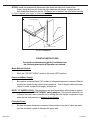
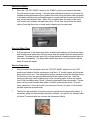
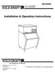
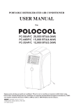
CLASSIC
K O L D-D R A F T
GT Ice Maker Models
Installation and Operation Instructions
CHECK FOR FREIGHT DAMAGE BEFORE PROCEEDING: Even though damage to
the carton may not be evident, check for hidden damage and if found contact the freight
carrier immediately to file a claim.
THIS EQUIPMENT MUST BE INSTALLED IN COMPLIANCE WITH ALL APPLICABLE
FEDERAL, STATE/PROVINCE, AND/OR LOCAL PLUMBING, ELECTRICAL, AND
HEALTH/SANITATION CODES AND REQUIREMENTS.
Failure to understand and follow these
instructions could lead to the following
Risks and Damage
CAUTION:
" RISK OF PERSONAL INJURY, PROPERTY DAMAGE, EQUIPMENT
FAILURE, OR FIRE.
" Refer all maintenance to qualified personnel.
" Never operate this equipment with covers, panels, or other parts removed
or not properly secured.
" Warn all users to clean up all spills immediately, keep storage bin doors
closed, and report any leaks or unusual sounds to responsible
maintenance personnel.
" Use suitable lifting techniques and watch for sharp edges.
" Failure to follow all installation specifications and instructions may
cause: improper operation and equipment damage or fire.
1525 East Lake Road, Erie, PA 16511-1088
www.kold-draft.com
Phone 814-453-6761
Fax 814-455-6336
©2005 KDIndustries, Inc., Erie, PA U.S.A.
508107002
1
Rev.02/05
Installation Specifications
Ampacity: Minimum ampacity does not indicate typical running current value. Refer to equipment
NAME PLATE data. Use minimum ampacity value for sizing branch circuit conductors up to 25
feet length. For conductor length over 25 feet up to 100 feet, increase 1 AWG size. Over 100
feet requires 2 or more AWG size increase.
Branch circuit protection: Proper protection must be provided by either fuse(s) or HACR type
circuit breaker(s). Each cuber must be provided with a separately protected circuit with no other
load(s). A fused disconnect installed adjacent to each ice maker is recommended , and may be
required by local codes. NORMAL protector size is based on rated voltage and operation at
lower than extreme temperature limits. When branch circuit conductors are sized to permit,
increasing the protector size (up to the specified maximum) may avoid nuisance protector opening
under harsh operating conditions.
Water supply: Minimum 20 psig supply pressure while the ice maker is filling is required. Maximum
supply pressure is 100 psig. The water fill flow rate is 0.6 GRM for each GT3XX and 1 GPM for
each GT5XX machine. Backflow prevention is provided by an internal air gap (accepted by
NSF). If additional protection is required by local codes, any device(s) and installation of the
same, including specification and cost, are the responsibility of the installation specifier.
Ice maker drain: The size of the gravity drain for the ice maker rinse and purge water must not
be reduced. Individual drains from stacked ice makers may be discharged into a standpipe or
manifold with a minimum 1-1/2 inch air gap at each ice maker connection.
Liquid condenser coolant pressure drop: Condenser coolant pressure drop may reach 20 psig
during peak load with 85OF. coolant temperature at recommended refrigerant high-side pressure.
The condenser coolant (water) regulating valve may require adjustment due to variations in the
coolant supply characteristics to provide optimum efficiency.
All models are intended FOR INDOOR USE ONLY with PERMANENT CONNECTION TO THE
FIELD ELECTRICAL SUPPLY.
Note for GT5XX Series Only:
Remote air-cooled condensers supplied by KOLD-DRAFT may be installed
outdoors, and they require a separate electrical supply.
Other operating condition requirements:
Ice maker ambient air temperature: MINIMUM 45°F.; MAXIMUM 90°F.
Remote condenser ambient air temperature: CONSULT SERVICE MANUAL
*Ice maker ambient temperatures less than 50°F may cause erratic bin thermostat operation.
Potable water and condenser liquid supply:
Temperature: MINIMUM 45°F.; MAXIMUM 90°F.
Pressure: MINIMUM 20 psig; MAXIMUM 100 psig**
*Potable water temperatures less than 50°F are likely to cause cold-water thermostat operation
(see SERVICE MANUAL).
**If regulator is used, recommended setting is 30 to 50 psig.
508107002
2
Rev.02/05
INSTALLATION
NOTE: For Stacked GT3XX installations, refer to the specific stacking instructions before proceeding.
GT5XX ice maker cannot be stacked.
Location:
1.
Position the ice storage bin with the following minimum clearances around the ice maker
for ventilation and utility connections:
REAR :
RIGHT SIDE:
LEFT SIDE:
TOP:
GT3XX Ice Makers
6 inches
6 inches
6 inches
6 inches
GT5XX Ice Makers
8 inches
4 inches
4 inches
8 inches
Level Equipment:
2.
Level the bin with adjustable legs, or by shimming if the bin is to be sealed to the floor. If
gaps due to shims are greater than 1/8 inch, install a cove molding around the bin
bottom. Seal the bin or molding to the floor with NSF Certified RTV silicon sealant (DowCorning RTV 732 or equal).
Cabnet Panel, Ice Chute and Drain Pan Removal:
3.
Remove the cabinet panels as follows:
TOP: GT3XX, Lift the front edge and pull forward until the rear clip is
disengaged from the chassis.
GT5XX, lift the front edge and push backward until the rear
catch is disengaged.
FRONT:
Remove the (4) screws at the bottom and front-sides, pull forward.
SIDES :
Pull forward and lift to disengage the clips from the chassis.
4.
Remove the, ice chute and drain pan. Peel off the protective film from the ice maker and
the bin exterior panels.
Gasket the Bin Top:
5.
Install gasketing on top of bin. Gasket material must be positioned so that it extends to
all the outside edges of the ice maker chassis.
Position the Ice Maker on the Bin Top:
6.
508107002
CAREFULLY place the ice maker onto the bin, note the alignment of the mounting holes in
the ice maker if mounting means (holes) are provided on the bin. 1/4”-20 capscrews are
provided for securing the ice maker to bin. Consult the ice bin installation instructions for
for additional information.
3
Rev.02/05
Install the Ice Chute and Drain Pan:
7.
Install the ice chute / drain pan. On the GT3XX installations, route the drain tube
assembly through the rear of the bin and clamp the tubing to the drain pan nipple.
NOTE:
To avoid the RISK OF CONTAMINATION OF ICE IN THE BIN,
provide separate, unconnected, drains for the ice maker and the bin.
Consult local codes for suitable connections to the building drains.
Water Supply:
8.
Purge the potable water supply line.
Remove Shipping Strap:
9.
Remove the water plate shipping strap.
Install Thermostat:
10.
GT3XX: Install the insulated bin thermostat tube through the grommet, in the right
side wall of the frame, along the wall through the grommet in the drain pan
support. Push the tube down as far as it will go. Be careful not to kink the Thermostat
tube when bending it. Form it against your finger or other round object.
GT3XX Thermostat Installation
508107002
4
Rev.02/05
GT5XX: Install the insulated bin thermostat tube down the right-front corner of the
frame, along the front rail, under the right side drain pan flange, through the bulb
tube holder and down into the bin. Be careful not to kink the cap tube when bending
it. Form it against your finger or other round object.
BULB TUBE HOLDER
DRAIN PAN
FRAME
BIN THERMOSTAT TUBE
GT5XX Installation
START-UP INSTRUCTIONS
Consult the troubleshooting guide if variations from
the following description of operation are noticed:
Mode Selector Switch:
1.
Move the “ICE-OFF-WASH” switch to the center (OFF) position.
Power and Water Supply:
2.
Be sure that condenser liquid (“W” models) or refrigerant lines and condenser (Remote
models) are ready for use before turning power on. Turn on supply water and power.
Check for leaks in water/liquid supply connections.
NOTE, “R” MODELS ONLY: The compressor will start immediately when power is applied,
regardless of the “ICE-OFF-WASH” switch position, if the low-side pressure is at
or above the pump-down controller cut-in setting. Be sure that the compressor stops
when the low-side pressure is between 5 and 15 psig.
Prime the Pump:
3.
508107002
Be sure that pump hoses are connected, then put about one pint of clean tap water
into the circulation system to lubricate the pump seal.
5
Rev.02/05
Start the Ice Maker:
4.
Move the “ICE-OFF-WASH” switch to the “WASH” position and observe the water
fill cycle and the pump running. If all water plate distributor holes do not produce full
streams and the appearance of air is evident in the tube, pinch the plastic tube connected
to the water solenoid valve outlet while water is running until the streams are full all the
way across the distributor tube. Water fill is complete when the water in the liquid
level control tube reaches the high-level probe. At this time observe that the water
shuts off and that there are no water leaks (dripping into the drain pan).
Open the Water Plate:
5.
Pull the right end of the water plate down, stretching the springs until the pump stops,
and hold the water plate down until the pump does not restart when the water plate is
released. The water plate will open fully to dump the batch of water previously taken in,
then close immediately. The water plate should stop when it is fully closed, and the
water fill cycle will repeat.
Start Ice Production
508107002
6.
After the water fill is complete move the “ICE-OFF-WASH” switch to the left “ICE”
position and observe that the compressor (and fan in “A” models) starts, and the water
pump continues to run. The refrigeration system operation should be checked during
the first few cycles, and any adjustments should be made at this time. Initial ice
making cycles may exhibit supercooling of the circulating water so that ice crystals
form in the circulating water (“slush”), possibly stopping the flow momentarily. If water
goes over the control stream dam when circulation resumes after three (3) cycles,
close expansion 1/4 turn and cycle for a minimum of three (3) cycles, if the problem
persists repeat the previous step.
7.
Test the bin thermostat(s) by holding some ice against the bin thermostat tube(s). If
necessary, adjust the thermostat(s) sensitivity towards + so that the ice maker(s) shut
off within 30 seconds after ice contacts the thermostat tube(s).
6
Rev.02/05
Clean Up:
8.
Discard ice from start-up cycles, then clean and sanitize the bin following the
instructions provided with the bin.
Registration and Instructions:
9.
Complete and mail the Registration Certificate and leave this manual with the owner/
user. Emphasize the “CAUTION: RISK OF PERSONAL INJURY...” NOTICE ON
THE COVER OF THIS DOCUMENT.
10.
Reinstall the cabinet panels even if the ice maker will not be operated immediately.
WATER LEVELS, CYCLE TIMES, AND REFRIGERANT CHARGES
K
W ater fill level (Top of tank to level in control tube, inches)
Approximate cycle time, minutes
Approximate harvest weight, pounds
MODE L NUM BE R
GT35X
GT55X
C/HK
K
C/HK
3
14
2
2.63
28
3.5
3.63
15.5
4
2.75
31/24
7.7/7.1
* Values are for Air-cooled model at 90°F air and 70°F water temperatures with ice maker
adjusted to produce fully-formed ice. Greater ice capacity can be obtained by reducing the
water fill level (lowering the high-level probe) to produce ice with larger dimples. A slight
adjustment of the probe will result in a noticeable effect on dimple size. The control stream
will not rise over the dam with lower water fill levels than indicated above.
TYPICAL REFRIGERANT OPERATING CONDITIONS
All pressures are psig
TIME
HIGH-SIDE
LOW-SIDE,
R-404a
W
R-404a
A
R
Beginning of
freeze cycle
Approx. 50
250*
**
200 Min. ****
Just before
harvest
12 to 20
250*
***
200 Min. ****
Harvest
cycle
70 to 150
Approx. 150 Approx. 150
150
Minimum
All pressures may vary with operating conditions and adjustments.
*
104o F condensing temperature—adjustable with coolant regulator valve.
**
High-side pressure at beginning of freeze cycle in “A” models is likely to be
higher than pressures shown for “W” models.
***
High-side pressure just before harvest in “A” models in cool ambients is likely to
be lower than pressures shown for “W” models.
**** See remote condenser charging requirements if lower than minimum shown.
508107002
7
Rev.02/05
Kold-Draft Ice Ma0er Installation Chec0list
!
Are the ice ma+ers and bin level2
!
Is there proper clearance around the machine for air circulation2
!
Have all electrical, water and sewer connections been made2
!
Has the suppl; voltage been tested with the ice ma+er on a dedicated, protected circuit2
!
Is the machine installed where ambient air temperatures will range from 45 to 90F (7 to 32C)2
!
Is the machine installed where incoming water temperatures will range from 45 to 90F (7 to 32C)2
!
Does the water suppl; provide a minimum 20 psig d;namic to maximum 100 psig static pressure2
!
Is there a separate drain line for the water cooled condenser2
!
Are there separate drain lines for the ice ma+er and bin2
!
Are the ice ma+ers and bin drains vented2
!
Is the bin thermostat run correctl;, secured, tested and positioned in the bin at the right level2
!
Is the gas+et positioned between the perimeter of the ice ma+er and bin top2
!
Are the electrical lines free from contact with refrigerant lines and moving parts2
!
Are the drain pan and ice chute positioned properl; and is the pac+ing tape removed2
!
Has the start up process been completed with good ice qualit;2
!
Have ;ou cleaned and sanitized the ice ma+er and bin2
!
Is the mode selector switch set to the ice position2
!
Are the cabinet panels secured2
!
Has the owner been instructed regarding cleaning, maintenance and the high pressure reset button2
!
Has the owner completed the registration card2
!
Have ;ou left the installation and operation manual2
Additional Remote Model Chec0list
!
Does the remote condenser fan operate properl;2
!
Are the refrigeration lines run so the; donMt form a trap, other than a service loop at the bac+ of the ice
ma+er, or sit in water2 Is an; excess tubing located indoors2
!
Is the refrigeration discharge line, to the remote condenser, insulated2
!
Is the s;stem adequatel; charged considering ambient temperature, line length & condenser volume2
508107002
8
Rev.02/05