1
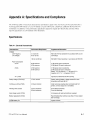
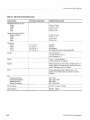
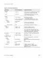
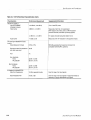
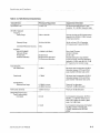
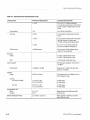
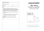
®
Advanced Test Equipment Rentals
www.atecorp.com 800-404-ATEC (2832)
User Manual
E stablished 1981
Tektronix
/
2721A/2722A
Non-Interfering Sweep System
070-8743-00
Please check for change information at the rear
of this manual.
First Printing June 1993
Revised October 1993
Introduction
Options
Power Supply
When one of the following power plug options is ordered with a transmitter or
receiver. the product will be shipped with a 220V/240V. 50 Hz power supply in
place of the standard power supply.
Option
Option
Option
Option
2722A Receiver
A1
A2
A3
A5
Universal Europe (locking cord)
United Kingdom
Australia
Swiss
In addition to power supply options. there are three options that can be ordered
for use with the swecp system. AII three options are for the recei ver:
Option 01
Option .13
Option 35
YT-1 Chart Recorder
Nylon Carrying Case with Hand/Shoulder Strap
Steel Safety Latch Hook
Standard Accessories
The following accessories are included with the sweep system:
2721A Transmitter
2.
2722A Receiver
Power Supply, 120 V, 60 Hz, with Captive Power Plug
Precision Pemale-Female Type F Adapter
Rack Rails
2721 A/2722A User Manual
Power Supply, 120 V, 60 Hz, with Captive Power Plug
Precision Female-Female Type P Adapter
RS-232C Cahle
Voltmeter Lead Set
Download Software
2721 AI2722A User Manual
Optional Accessories
The following accessories can be purchased for use with the sweep system:
2721 A Transmitter
070-8756--00
2721 A/2722A Service Manual
2722A Receiver
006-7647-00
Thermal paper for YT-I (Single)
Thermal paper for YT-I (Box of 25)
BNC-to-F Adapter
Rechargeable 12 V Battery (See Appendix B)
2721 N2722A Service Manual
006~7677-00
103-0310-00
146-0080-00
070-8756-00
Ordering
All listed options and accessories can be ordered with the transmitter or receiver.
Accessories are also available through your Tektronix field office or distributor.
1-8
REV OCT 1993
2721 A/2722A User Manual
Appendix A: Specifications and Compliance
The following tables of electrical characteristics and features apply to the 2721 A/2722A Sweep System after a
warm-up period (60 minutes 2721 A, 10 minutes 2722A) followed by a hardware calibration between the two
instruments. In addition, some performance parameters depend on signals provided hy the customer. These
requisite parameters are also defined in this document.
Specifications
Table A-1: Electrical Characteristics
Characteristics
Performance Requirement
Supplemental Information
POWER
Line Frequency
Line Voltages
47.5 to 63 Hz
90 to 132 Vac
With 120 V/18 Vac transformer in accordance with Ul and
CSA ratings.
180 Vac to 250 Vac
With 220V/19Vac transformer in accordance with IEC 950.
60W maximum
48 W maximum
47 W typical, input to transformer.
36 W typical, AC input to instrument.
43 W maximum
30W maximum
31 W typical, input to transformer.
20 W typical, AC input to instrument.
Battery: 23.5 W maXimum, 17.7 Wtypical (2.2 A
maximum at 10.7 V, 1.4 A typical at 12.6 V).
Power Consumption
2721A
2722A
YT-1 printer
Typically 6 Q additional load while printing.
Battery voltage (2722A only)
12 Vdc, nominal
Sealed, lead-acid battery; voltage measured at room
temperature with back light off.
Continuous runtime (2722A)
2.5 hours minimum
Under worst-case loading (does not include load from
printer); 3.5 hours typical for a new battery.
Recharge time (2722A)
15 hours maximum
24 hours maximum
From "BATlO" threshold.
From total discharge.
Input charge current (2722A)
0.5 A typical, with external transformer supplied.
Battery replacement (2722A)
Recommended when runtime is less than 2.5 hours typical
after full charge.
NVRAM battery life
6 years minimum.
2721 N2722A User Manual
A-1
Specifications and Compliance
Table A-1: Electrical Characteristics (Cont.)
Characteristics
Performance Requirement
Supplemental Information
Weights & Dimensions (2721 A)
Weight
Height
Width
Depth
6.2 Kg (13.75Ibs)
4.45 cm (1.75 in)
48.3 cm (19 in)
48.3 cm (19 in)
Weights & Dimensions (2722A)
Weight (w /battery)
Height
Width
Depth
8.0 Kg (17.75Ibs)
27.9 cm (11 in)
22.8 cm (9 in)
22.8 cm (9 in)
Temperature
2721A
2722A
2721A
2722A
15° C to 45° C
0° C to 50° C
-20° C to 75° C
-20 0 C to 60° C
Operating
Operating
Non operating
Non operating (to maintain backup battery life)
Humidity
<95% RH below 30° C
<75% RH from 30° C to 40° C
<45% RH above 40° C
Altitude
4,575 m (15,000 tt) operating
12,000 m (40,000 tt) non operating
Vibration
Resonant searches of 0.013 inches on all three axes for 15
minutes. Dwell for 10 minutes at major resonance or 33 Hz
if none. Total vibration time is 75 minutes.
Shock
Three gUillotine-type shocks of 60g, half sine. 11 ms
duration in each direction along each major axis; total of
18 shocks.
-
EMI
Conducted Emissions
Conducted Susceptibility
Radiated Emissions
Radiated Susceptibility
CE01,
CS01,
RE01,
RS01,
CE02
CS02, CS06
RE02
RS02, RS03
FCC Compliance
FCC Part 15, subpart J, Class A
VDE Compliance
VDE 0871, Class B
A-2
2721 A/2722A User Manual
Specifications and Compliance
Table A-2: 2721A Electrical Characteristics
Characteristics
Performance Requirement
Supplemental Information
Return Loss
Output
>16 dB, 75 Q
At the output terminal, with 6 dB pad and precision F-style
connector. Over 15 - 600 MHz frequency range.
Input
>16dB,75Q
At the input terminal, with precision F-style connector.
Over 15 - 600 MHz frequency range.
14 IJsec ±0.333 IJsec
Measured at 50% of amplitude.
±3 IJsec allocated to Sync board.
±1 IJsec allocated to Up/Down converters. Position
specification for Std and RF Suppression modes only.
Test pulse
Duration
Position
Frequency
Range
Accuracy
Step size resolution
Amplitude
Non-gated
Gated
11.5 IJsec ±4 IJsec after midpoint
of first post-equalizing pulse
5 MHz to 600 MHz
±5.0 KHz
At frequency point nearest 600 MHz.
At 25'" C; frequency nearest 600 MHz.
40 KHz
Test pulse frequency user-definable to +40 kHz, -0.
+45 dBmV ±1.0 dB
+33 dBmV ±1.0 dB
Insertion level 6 dB below video carrier.
Insertion level 18 dB below video carrier.
At 25° C when leveled at factory with 0 dB tilt. Tilted
output available in 2, 4, 6, 8 dB slopes. Output amplitudes
apply to maximum pulse frequency. Amplitude drift:
s-0.07 dB/O C typical (0.1 dB/o C maximum), 15-45" C.
Spurious signals
Out of band
<-11 dBmV (-60dBm)
::;+24 dBmV (-25 dBm)
TELEMETRY CARRIER
Format
Frequency
Range
For frequencies s 740 MHz, measured with pulse carrier
on.
For frequencies> 740 MHz.
Frequency Shift Keyed (deviation = 170 kHz nominal).
15 MHz to 600 MHz
User selectable.
Measured with Sweep mode disabled, at point nearest 600
MHz.
Accuracy
±5.0 KHz at shift point
Sweep mode stopped.
Resolution
40 KHz
Amplitude
2721 A/2722A User Manual
+45 dBmV ±0.5 dB
+45 dBmV ±3 dB
+45 dBmV ±0.5 dB at 25 0 C, 50 MHz.
+45 dBmV ±3 dB at 25° C, 15 MHz to 600 MHz.
Amplitude drift: s -0.07 dB/a C typical (0.1 dB/o C
maximum), 15 to 45 0 C.
A-3
- - - - - - - - _ .. - - - - _
Specifications and Compliance
.. -.
---- - - - - - - -
--------.
- - ~ -
Table A-2: 2721A Electrical Characteristics (Cont.)
Characteristics
RF INPUT SIGNALS
Input NO DAMAGE
Amplitudel channel
Video Carrier
Audio Carrier
RF Input Signal Baseband Characteristics
Video Modulation Formats
Supplemental Information
+16 dBmW (+65 dBmV)
Sum of total RF power.
10 dBmV to +10 dBmV
For signals encoded using Oak Sigma format.
-15 dBc±3 dB
Measured at the TV modulator in all supported modes.
NTSC or PAL
SECAM guaranteed by design but not tested (not
compatible with SECAM-L systems).
30 dB
Hum
3%
Sync Amplitude
NTSC
PAUSECAM
40 IRE ±10 IRE
300 mV ±75 mV
Burst Amplitude
NTSC
PAUSECAM
40 IRE ±10 IRE
300 mV±75 mV
Audio Modulation AM
Measured at Sync tip, non-suppressed.
With respect to the video carrier, all AM modulation
sources removed (scrambler sync timing signals).
+3 dBmV to +13 dBmV
Recovered video SIN (baseband
and cable noise only)
SCRAMBLER PARAMETERS
Video Sync Suppression
A-4
Performance Requirement
10 dB in supported modes.
Over full range of all input signals.
+6 dB ±2 dB
Over full range of all input signals in supported modes as
necessary to recover appropriate sync signals.
2721 A/2722A User Manual
Specifications and Compliance
-
---
-
-
Table A-3: 2722A Electrical Characteristics
Characteristics
Performance Requirement
Supplemental Information
Input Return Loss
>14 dB, 75 n
At input terminal with precision F-style
connector. 30 - 600 MHz frequency range.
RF INPUT SIGI\IALS
Frequency
Sweep Range
5 MHz to 600 MHz
Accuracy of pulse and SLM measurement
degrades from 30 MHz to 5 MHz because
of start spur presence.
Telemetry Range
15 MHz to 600 MHz
40 kHz; will track 2721A Transmitter
At Frequency point nearest 600 MHz.
Conversion Resolution Accuracy
5 kHz
Amplitude
Input NO DAMAGE
Attenuator Range
Preamp Gain
Hardware Calibration
+16 dBmW (+65 dBmV)
20 dB minimum
50 dB maximum attenuation
15 dB minimum attenuation
Sum of total RF power.
44 dB in 2 dB steps.
23 dB ±2 dB.
Allowable attenuation range between
2721 A and 2722A; maximum attenuation
reduced by .5 dB for each dB of tilt. 10 dB
pop maximum error correction range.
Pulse Sensitivity
Non-Gated mode
-5 dBmV
Mid-screen level corresponds to 50 dB of
attenuation between 2721 A and 2722A,
pulse inserted 6 dB below video carrier.
Gated mode
-17 dBmV
Mid-screen level corresponds to 50 dB of
attenuation between 2721 A and 2722A,
pulse inserted 18 dB below video carrier.
+10 dBmV minimum
+54 dBmV maximum
Preamp off, no attenuation.
Preamp off, 44 dB of attenuation.
FSK receiver sensitivity
-5 dBmV minimum
Preamp off, 36 dB attenuation.
Sweep Response Accuracy
Peak-to-valley reading
Normalized
±0.5 dB
At normalization temperature, 30 MHz to
600 MHz, ±1.5 dB when sweep trace is
within 6 dB of bottom of screen in gated
mode. For 0 dB tilt only.
±1.0 dB
At normalization temperature when System
Test Plan consists of channels with
"OTHER" selected as the "DECODE
MODE."
SLM Sensitivity
Reference level range
2721A/2722A User Manual
A-5
Specifications and Compliance
Table A-3: 2722A Electrical Characteristics (Cont.)
Characteristics
Performance Requirement
Supplemental Information
±1.0dB
For 0 to 50
30 MHz to 600 MHz,
±1.5 dB when sweep trace is within 6 dB of
bottom of screen in gated mode. For 0 dB
tilt only.
Unnormalized
7 dB
From 30 MHz to 600 MHz.
Ref value
±0.5 dB
At normalization temperature and center
screen.
±1.0 dB
At normalization temperature when System
Test Plan consists of channels with
"OTHER" selected as the Decode Mode.
±1.5 dB
For 0 to 50°C over entire screen with
2721A at normalization temperature.
±2.0 dB maximum
Over the upper 40 dB of display range;
preamp off. non-scrambled.
SLM Accuracy
Resolution
Sweep
ac,
0.2 dB in 20 dB full-screen mode.
0.1 dB in 10 dB full-screen mode.
SLM
1.0 dB in Quick Check level mode.
Spurious signals
Pulse channel
With equivalent loading of 105 carriers at
+10 dBmV.
<-50 dBmV (-60 dBc)
Measured at 21.4 MHz with input video
carriers at +10 dBmV.
5 to 80 V ac and dc
AC measurement is True RMS over 40 to
63 Hz frequency range.
±1.5 V; 5 V to 35 V
±2.0 V; 35 V to 80 V
In LOW range.
In HIGH range.
±0.5 V; 5 V to 35 V
±1.5 V; 35 V to 80 V
In LOW range.
In HIGH range.
Internal Battery volts
Range
Accuracy
+7to +15 V
±0.5 V
Measured across the battery terminals
under full load.
External Temperature Probe
±2° C from 0° C to 50° C
When exposed to ambient air, with the
Option Port door open.
Voltmeter
Range
Accuracy
AC volts (True RMS)
DC volts
A-6
2721 A/2722A User Manual